XCMG XE210C Hydraulic Excavator. Operating & Maintenance Manual (2011) - page 3
r
43
When the engine is running, two persons carry out the maintenance.
To prevent damage, when the engine is running, the maintenance should not be carried out. If the
maintenance must be carried out when the engine is running, two persons operate at least, and do following
rules::
z
One person must sit in the operation seat and be
ready to shut off the engine. All persons must keep
in communication with each other.
z
Pull the safety lock control rod to the locked position.
z
When operate near fan, fan belt or other rotating parts, the operator must pay special attention to
prevent being coiled.
z
Prohibit touching any operating lever. If necessary, the operator needs to send signals to other persons
to warn them moving to a safe place.
z
Never insert tools or other objects into the fan or the fan belt, otherwise the parts will break or fly out.
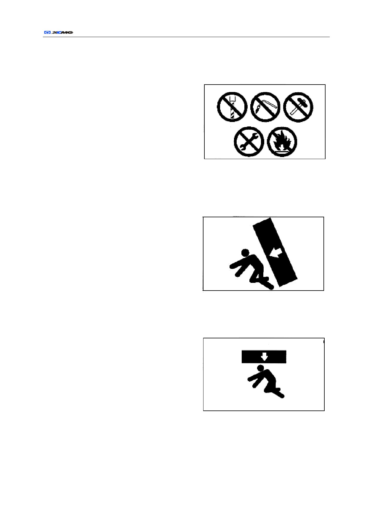
Suitable tools
The suitable tools should be correctly used, and damage,
inferior, flawed and temporary tools or inappropriate tools
may cause serious injury.
r
44
Energy container
The energy container is filled with high pressure nitrogen.
When operating on the energy container, the careless operation will cause explosion, and cause serious injury or
damage. Therefore, the following matters need to be paid attention:
z
Do not decompose the energy container.
z
Do not approach the energy container to the fire.
z
Do not punch and weld on the energy container, or
use the welding torch on the energy container.
z
Do not collide or roll the energy container, and do
not make the energy container suffer any impact.
z
When disposing the battery, gas must be
discharged.
Please contact with XUGONG excavator dealer to deal
with this task.
Personnel
Only trained personnel is allowed to maintain or to repair the machine, no one without training is allowed to
enter the area.
Accessories
z
Before removing or installing the accessories, a
header will be commanded.
z
The accessories which are removed from the
machines should be put in a stable place where the
accessories do not fall. Measures should be taken
to prevent unauthorized persons from entering
storage area.
Working under the machines
z
If the low surfaces of the machines or the working device need to be maintained, pads and frames
which are strongly enough to support the weight of the working device and the machine should be
used to support the working device and the
machine.
z
If the crawler belt leaves the ground, the machine
is only supported by the working device; if the
operating lever or hydraulic pipes are accidentally
touched, the working device or the machine may
suddenly fall. If the pads or the frames are not used
to support the machines, working under the
machine is prohibited.
r
45
Noise
z
If the noise of the machine is too loud, temporary or permanent hearing problems can be caused.
z
When persons maintain the engine and suffer the noise for a long time, ear covers or earplugs should
be worn.
Using the hammer
When using the hammer, pins may fly out, metal particles may scatter, the serious damage can be caused, and
then, the following steps need to be followed:
z
If the hammer is used to strike hard metal parts,
such as pins, bucket teeth, blade or bearings,
fragments may scatter and cause harm, and
therefore, goggles and gloves should be worn
during operating.
z
When striking the pins or the bucket teeth, the
fragments may fly out, the surrounding area must
not have persons, and then, the injury is avoided.
z
If struck strongly, the pins may fly out and cause
damage to the surrounding persons.
Welding operation
Only the proper device can be used, and the operation shall be performed by qualified welders.
Removing the battery terminals
When repairing electrical systems or welding, the terminals of the battery anode (-) will be dismantled, which
prevent the current from flowing.
r
46
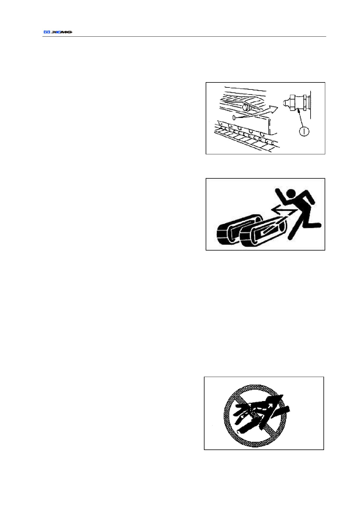
When the crawler belt tension is adjusted with high-pressure grease, the safety need be
paid attention to.
z
The grease is pressed into the crawler belt tension adjustment system under the condition of high
pressure. When adjusting, if the maintenance
procedure is not observed, the grease emission plug
①will fly out, which will cause serious injury or
damage.
z
In order to relax the crawler belt tension, the grease
emission plug ① is loosened, the emission plug
which is loosened is not turned over one lap, and
simultaneously, the grease emission plug must be
loosened slowly.
z
Do not approach face, hands, feet or other body parts
to the grease emission plug ①
Do not remove the buffer spring
The buffer spring assembly is used to alleviate the impact force of tension pulley, the buffer spring includes a
high-tension spring, if the high-tension spring is removed in a wrong way, the spring will fly out, which
causes serious injury or death.
Relevant safety rules of high pressure oil
The internal part of the hydraulic system always has pressure; when checking or replacing pipes or hoses, the
pressure in the hydraulic oil pipe must be checked whether has been released or not. If oil pipe still has the
pressure, serious injury or damage can be caused, so the following rules need to be done:
z
When the hydraulic system has the pressure, before releasing the pressure, do not carry out check or
replace.
z
If the surrounding area of the pipes or the hoses is wet, the pipes or the hoses should be checked
whether break or not, and whether the hoses inflate. When checking, goggles and leather gloves
should be worn.
z
The high pressure oil which leaks from small
orifices can penetrate into skin, and may cause
blindness if contact directly. If skin or eyes which
are contacted with the high pressure oil were injured,
skin or eyes should be flushed by clean water and
go to hospital for treatment.
r
47
Safe Operation of High Pressure Hose
z
If the hose leaks, it may cause fire or faulty operation, resulting in serious injury or damage.
If the bolt loose is found, stop operations and screw up/down the bolts to the specified tightening
torque. If there is any damage to the hose, stop the operation immediately, and contact with the
excavator dealer of XUGONG.
z
If there are any of the following problems, replace the hose:
- Damage or leakage of hydraulic pipe connection.
- Cladding frayed or disconnected, or strengthening layer wire exposed.
- Cladding expands in some places.
- Movable parts distorted or crushed.
- Impurities inside cladding.
Waste
To prevent pollution, particular attention should be paid to the treatment of waste:
z
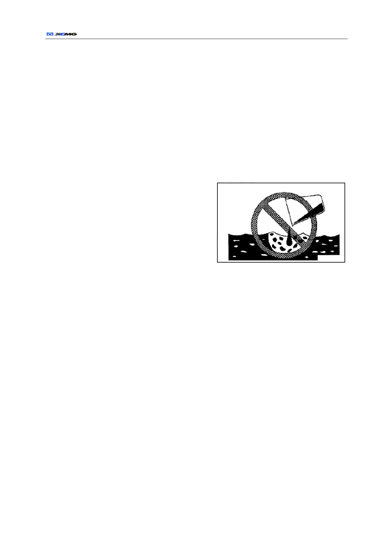
Discharge the oil from the machine into the
container; do not discharge it directly to the ground,
or into the sewers, rivers, oceans or lakes.
z
When dealing with hazardous materials, such as
engine oil, fuel oil, cooling fluid, solvents, filter and
batteries, it is necessary to comply
with the laws and regulations.
Air Conditioner Maintenance
If the air conditioner refrigerant gets into the eyes, it may cause blindness; if the refrigerant comes into
contact with skin, it can cause frostbite.
Compressed Air
z
When cleaning with compressed air, the particles flying out may cause injury on person or damage on
machines.
z
When cleaning filter or radiator with compressed air, make sure to wear goggles, dust masks, gloves
and other protective equipment.
Periodic Replacement of Safety-critical Parts
z
For long-term safety of in operation of the machine, there is need for regular lubrication and
maintenance. To further enhance security, the safety-related parts such as hoses, seat belts should be
periodically replaced.
z
When exceeds the allotted time, the material of parts will naturally change. Reuse will cause
deterioration, wear and damage. Finally, these parts may break down and cause serious injury or
damage. When the operating, it is difficult to judge how long these parts can keep working according
to an external inspection or touch, so replace it regularly
z
If there are any defects in safety-critical parts, replace or repair it even it has not reached the allotted
time.
r
48
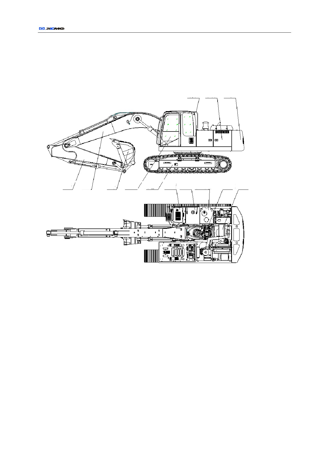
Name of Parts
General drawing
Engine Counter
Armrest
Case
weight
Bucket
Tool Diesel Hydraulic Hydraulic
Boom
Bucket
Cab Chassis
Engine
lever
case
tank oil tank
system
XE210/XE230/XE260C Hydraulic Excavator
49
Cab
Seat
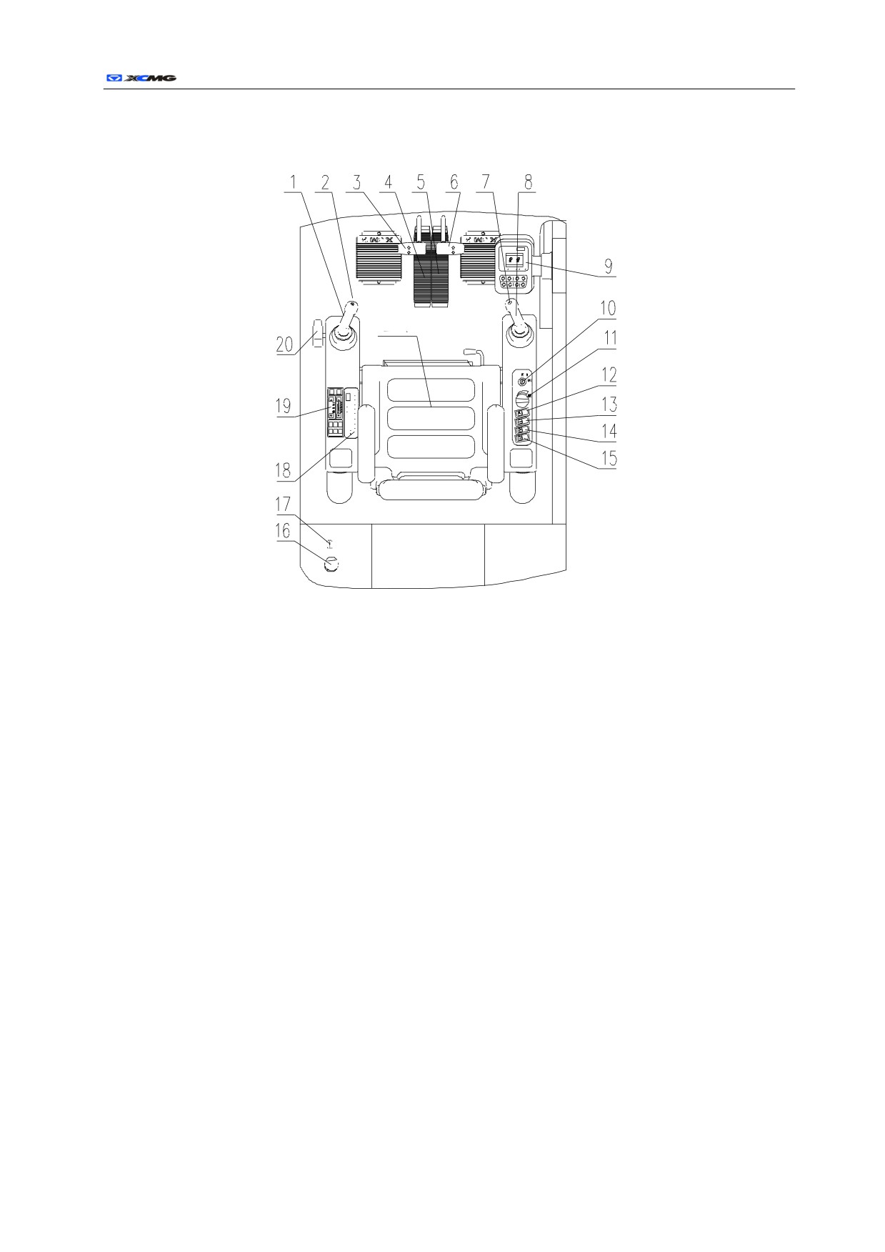
Fig.1-27 layout of operational and indicating parts in cab
1 left operational lever
2 horn switch(above left operational lever)
3 left treading control lever
4 left treading pedal
5 right treading pedal
6 right treading control lever
7 boosting switch (above right operational lever) 8 right control lever
9 monitor
10 key switch of engine
11 engine speed knob
12 switch for arm lamp
13 switch for working lamp
14 switch for wiper
15 switch for washer
16 button for emergency cutoff (optional attachment) 17 cigarette lighter
18 switch for radio
19 control button for air conditioner
20 safe locking lever
r
50
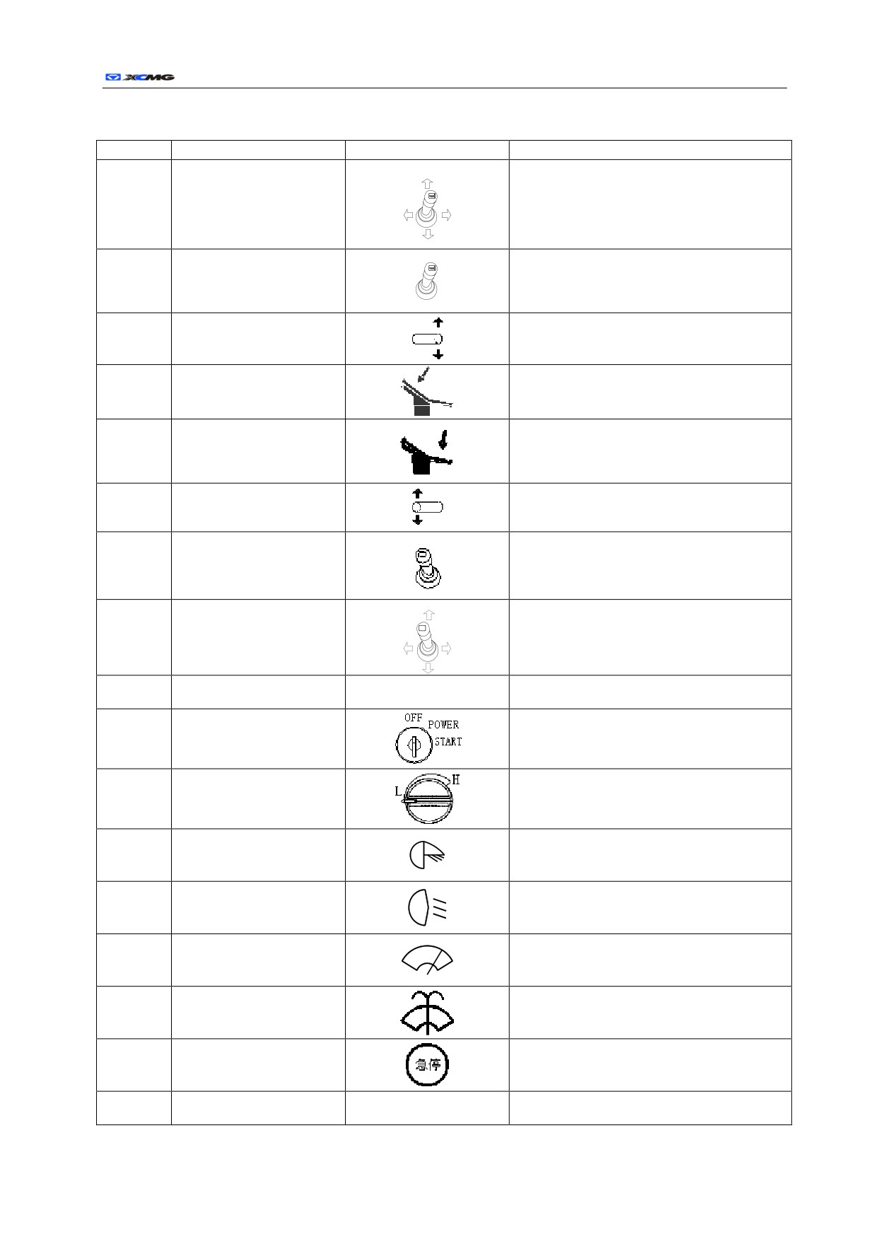
List 1-4 Illustrated signal
Serial No.
Name
Signal
Function
Control the arm stretching and retracting and the
1
Left operational lever
rotation of the up carriage
Horn switch (on top of left
2
Enable the horn to sound after being pressed
operational lever)
Control the advancement and reversing of leftside
3
Left treading control lever
crawler
Control the advancement and reversing of leftside
4
Left treading pedal
crawler
Control the advancement and reversing of
5
Right treading pedal
rightside crawler
Control the advancement and reversing of
6
Right treading control lever
rightside crawler
Boosting switch
(on top of
After being pressed, the max.excavation force can
7
right operational lever)
be obtained in short time
Control the rising and descending of moving arm
8
Right control lever
as well as excavation and unload of bucket
Operation, indication and warning(for details, see
9
Monitor
the latter introduction)
10
Key switch of engine
Start, run and stop the engine
11
Engine speed knob
Adjust the engine speed
12
Switch for arm lamp
Control the working lamp of moving arm
13
Switch for working lamp
Control the right working lamp
14
Switch for wiper
Control the wiper of front window of cab
15
Switch for washer
Control the washer of front window of cab
16
Button for emergency cutoff
Emergency cutoff of engine
17
Cigarette lighter
Control the lighting

r
51
18
Switch for radio
Control the radio
Control button for air
19
Control the air conditioner
conditioner
20
Safe locking lever
Control hydraulic guidance oil
XE210/XE230/XE260C Hydraulic Excavator
52
Monitor
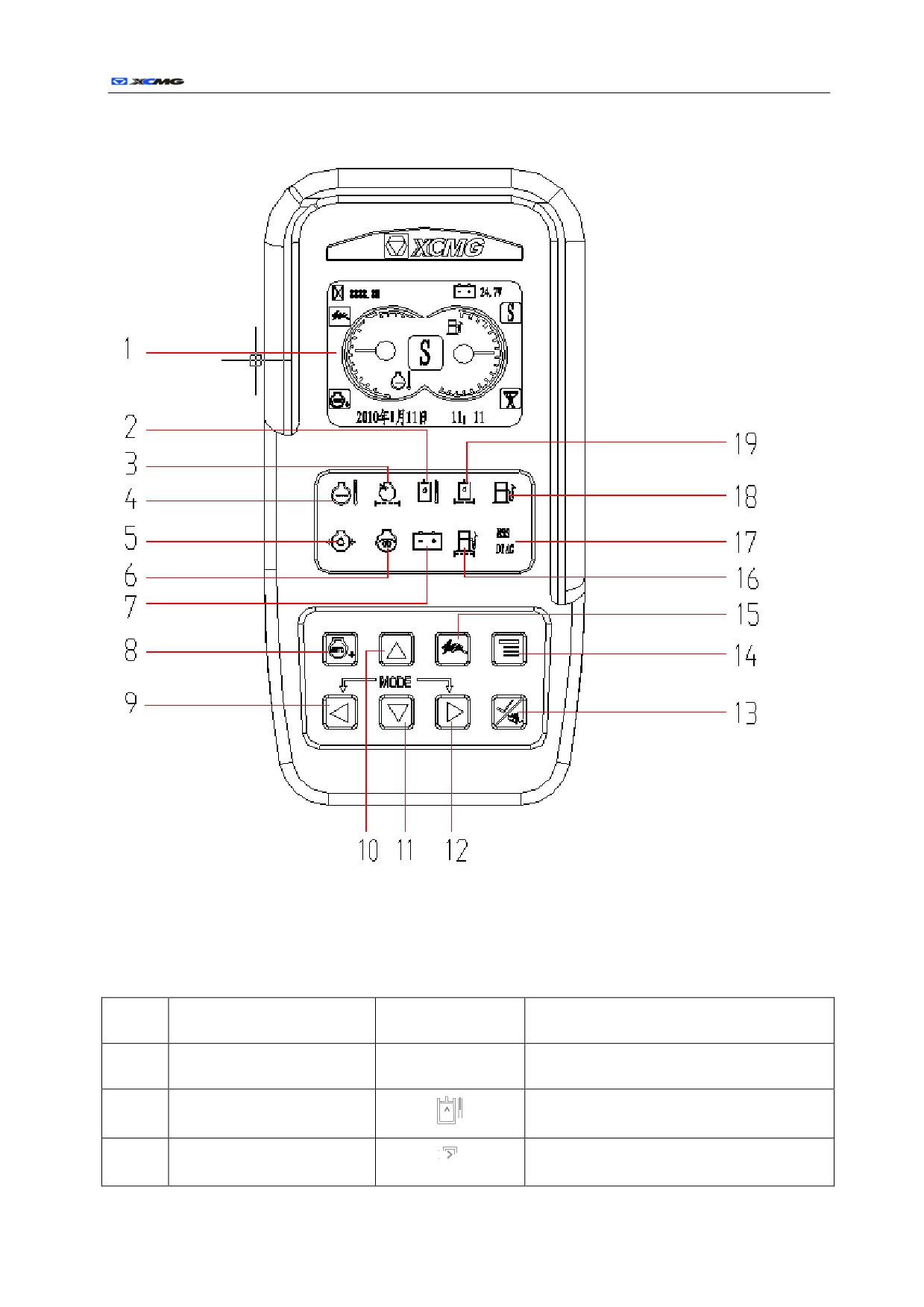
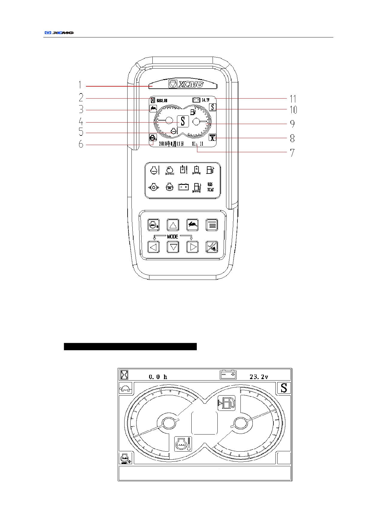
Fig. 1-28 Picture of monitor interface
List 1-3 List of illustrated signals
Serial
Name
Signal
Function
No.
Screen indication or main menu catalogue(for
1
Indication interface of screen
details, see the latter introduction)
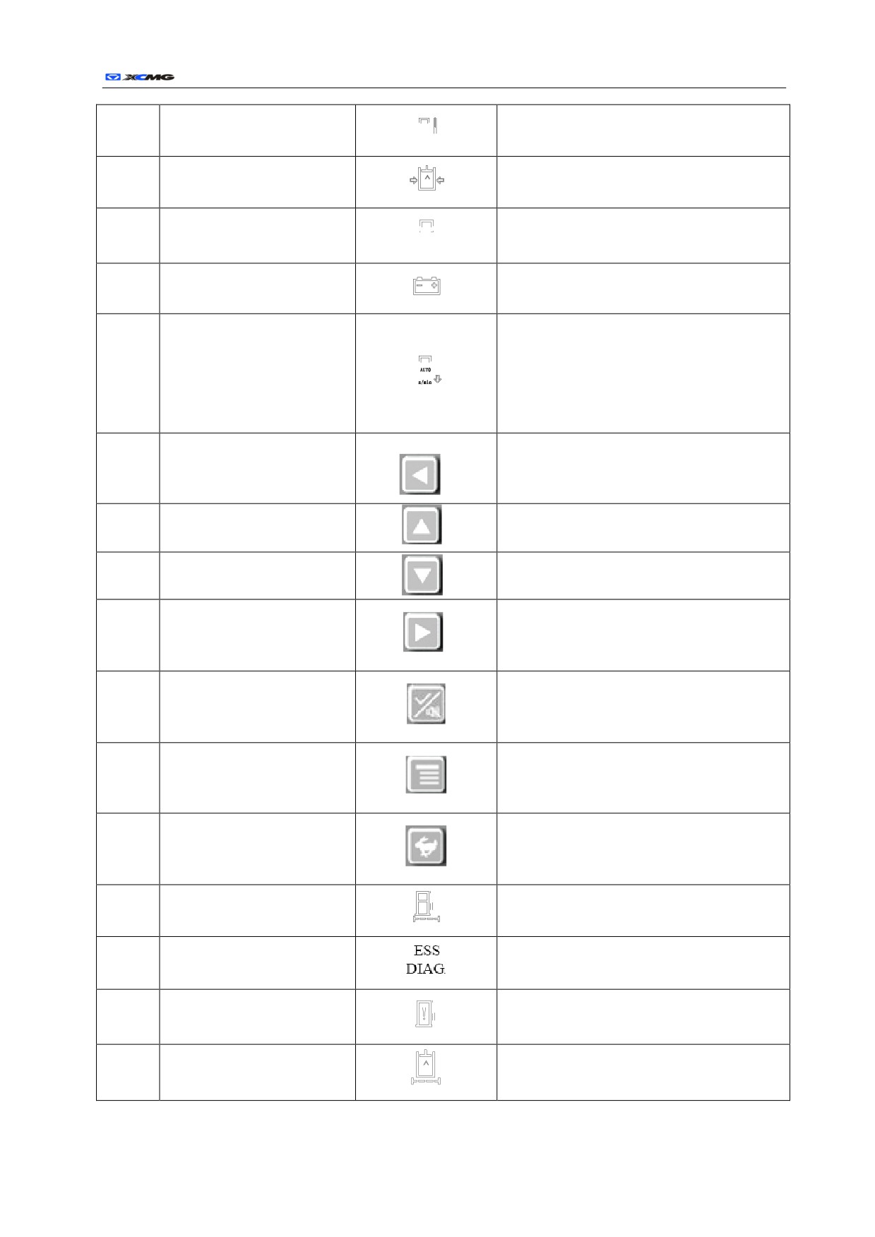
Alarm of hydraulic liquid
2
On for a high temperature
temperature
3
Air filter blockage alarm
On for a blockage in the air filter
r
53
Engine coolant high temperature
4
On for high temperature of engine coolant
alarm
5
Oil pressure alarm
On for low pressure of engine oil
6
Engine preheat indicator
On for the process of engine preheat
7
Charge alarm
On for abnormal engine battery charge
When the machine is started, automatic idle
speed is set by default. Being pressed once, the
8
Idle button
automatic idle speed is canceled. Being pressed
again, the automatic idle speed is restored.
When the machine is started, mode S works. Being
9
Button for choosing work mode
pressed once, circular options is made in order of
S→H→B→L→S
Being pressed, cursor move upward once after
10
Up/ button of increase
entering the main menu catalogue
Being pressed, cursor move downward once after
11
Down/ button of decrease
entering the main menu catalogue
When the machine is started, mode S works. Being
12
Button for choosing work mode
pressed once, circular options is made in order of
S→L→B→H→S
Being pressed, warning sound stops;
13
Muffling/identificating button
Confirm the cursor column after entering the main
menu
Being pressed once, it shows the optional indication
14
Button for menu/changing screen
interface in order of
“main menu→chart→main
menu” in cycle
Being pressed once, it shows treading mode will be
15
Fast/slow treading button
chosen circularly in order of “fast→slow→fast”
16
Fuel filter blockage alarm
On for a blockage in the fuel filter
17
Malfunction indicator
ESS malfunction indicator
18
Fuel oil level alarm
Leading hydraulic filter blockage
19
On for leading hydraulic filter blockage
alarm
r
54
z
Displaying interface of main screen:
1 Trademark
2 Working hour meter
3 Moving speed low/high indicator
4 Alarm and switch blink
5 Water thermometer
6 Automatic idle indicator
7 Time and information prompt
8 Instantaneous reinforcement indicator
9 Oil level display
10 Working mode indicator
11 System voltage indicator
z
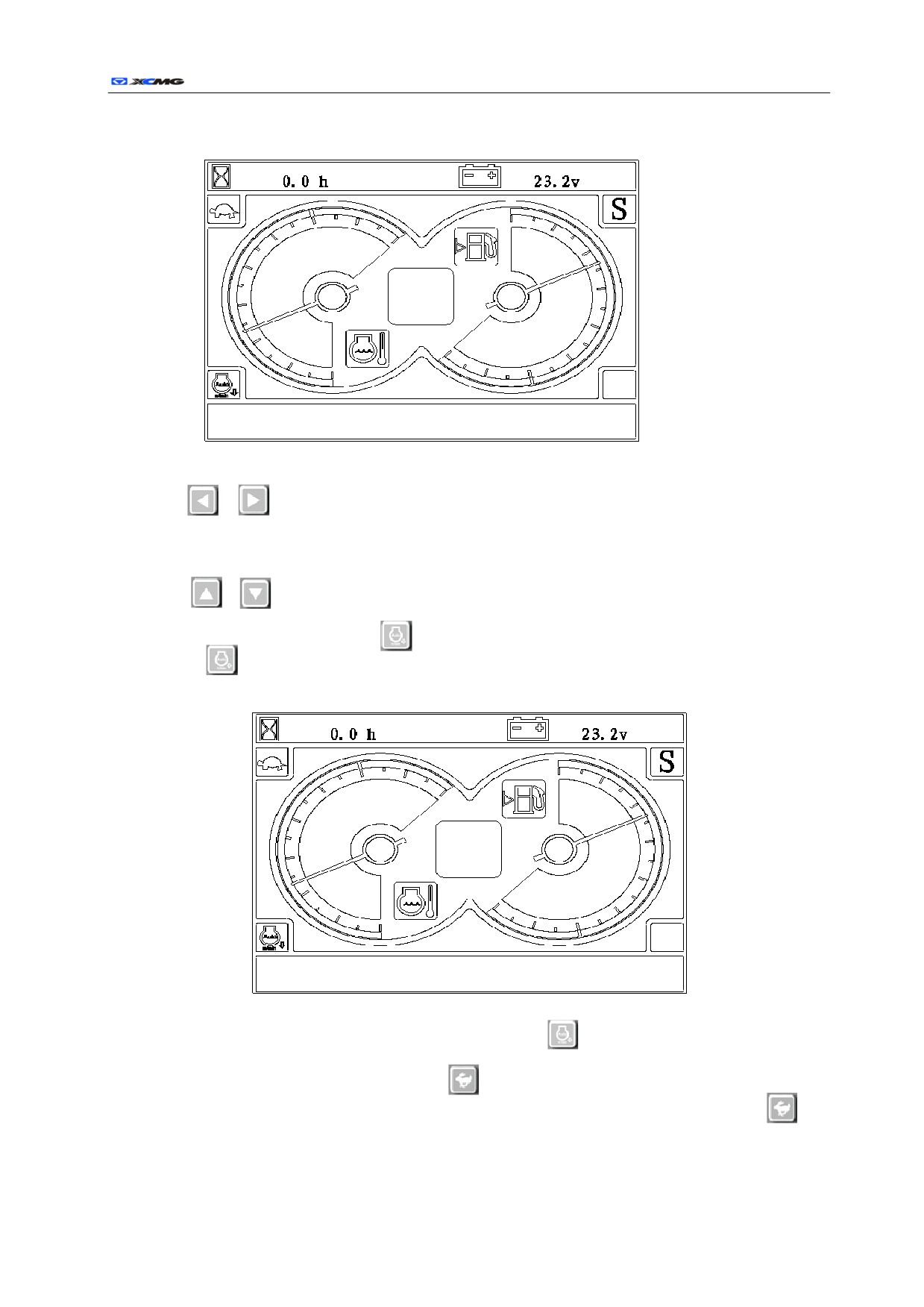
a) When the key switch is turned to ON, internal parameters initialization of the instrument is
started, and three seconds later, it switches to the following interface:
Date time and information display area
r
55
b) When the key switch is turned to ON, the interface of the instrument is as follows:
Date time and information display area
z
Button instructions:
a)
,
The two buttons are respectively corresponding to functions of the instruction area
between positive display liquid crystal to realize power mode switch. The switch can be carried
out in heavy load mode (H), simple load mode(S), light load mode (L) and pulverized load mode
(P).
b)
, The two buttons are respectively up key and down key when it comes to the menu,
through which required information can be chosen.
c) Automatic idle speed button
: after the automatic idle speed button is pressed, there will be
at
lower left. Three seconds later, the controller pulls the pointer from the current throttle
position to the idle speed position as follows:
Date time and information display area
after the automatic idle speed button is pressed again,
at the lower left disappears, and the
controller automatically pulls the pointer from the idle speed position to the throttle position.
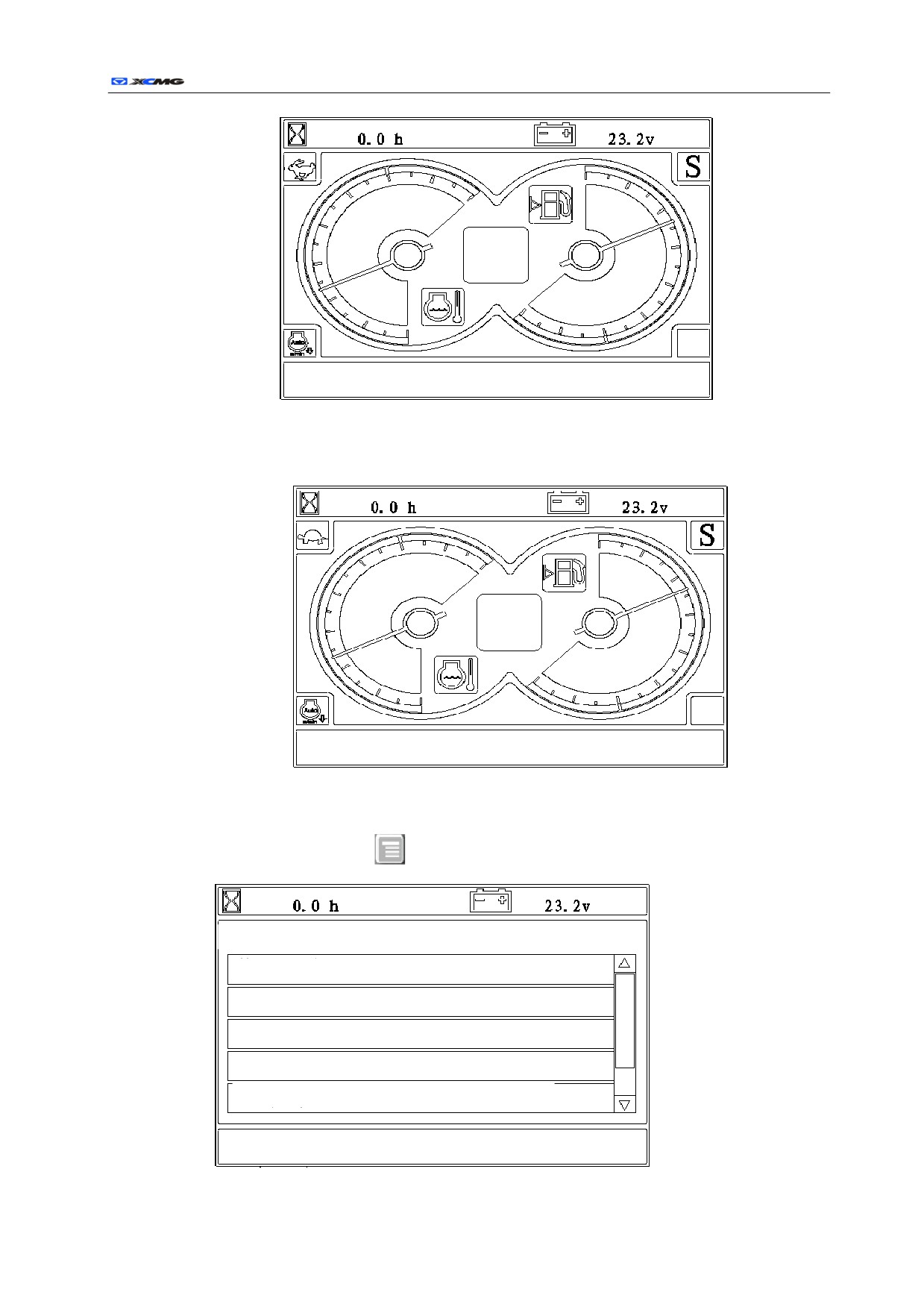
d) High and low speed moving button
after the key is pressed, the moving electromagnetic
valve obtains electricity, which enables high speed moving of the machine, the icon
will
appear at the upper left, as shown in the following figure:
r
56
Date time and information display area
When the key is pressed again, the moving electromagnetic valve loses electricity, and the machine
moves slowly. The interface is as follows:
Date time and information display area
z
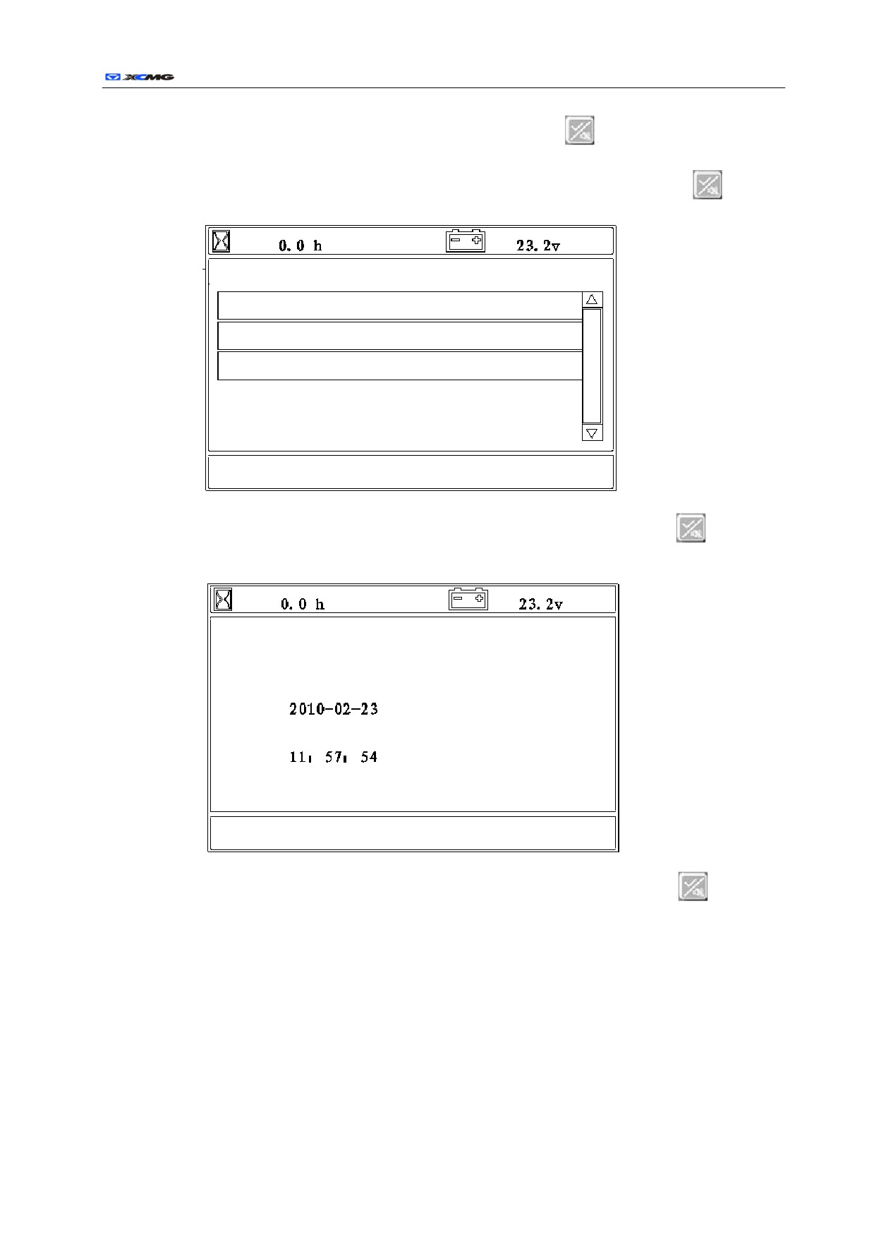
Menu operating illustration (For use only as operation demonstration, which may be different from
that of the machines):
a) Button operation in the working interface.
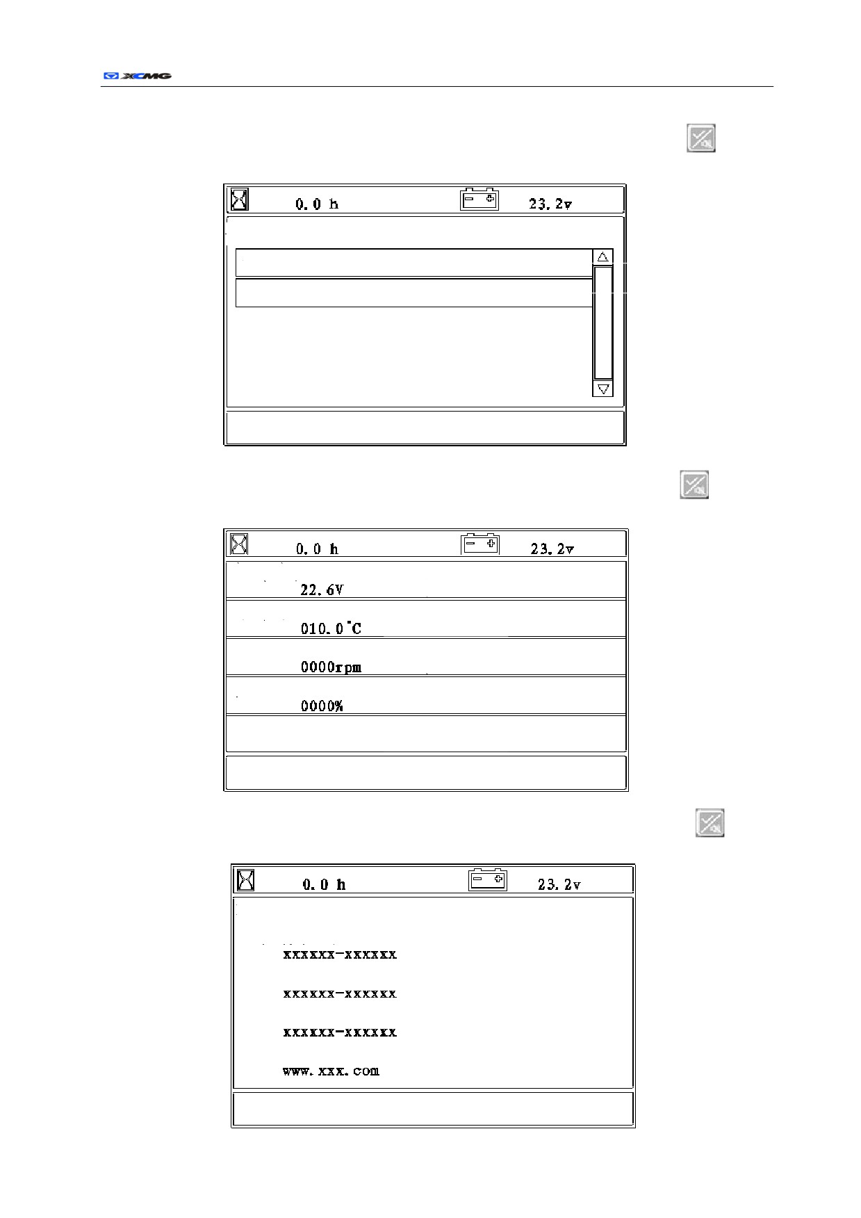
¾ When the menu key
is pressed in the working interface, the main menu interface is
entered as follows:
Main menu
Use information
Maintenance message
Users setup
System setup
GPS installation
Date time and information display area
r
57
¾ Choose use information in the main menu and press the confirmation key
, the use
information menu is entered as follows:
Use information
Detail information
Host information
Date time and information display area
¾ Choose in the use information menu and press the confirmation key
, specific
information is shown as follows:
Power supply
Normal
Coolant temperature
Normal
Engine speed
Normal
Fuel quantity
Warning
Oil pressure warning
Normal
Date time and information display area
¾ Choose in the use information menu and press the confirmation key
, host
information is shown as follows:
Machine information
Machine type
Machine serial No.
Service type 1
Website 1
Date time and information display area
r
58
¾ Choose in the main menu press the confirmation key
, the maintenance information
menu is entered, which shows maintenance details in each time period, and users can
keep maintenance accurately and timely.
¾ Choose user setting in the main menu and press the confirmation key
the user
setting menu is entered as follows:
User adjustment
Clock adjustment
Language setup
Brightness control
Date time and information display area
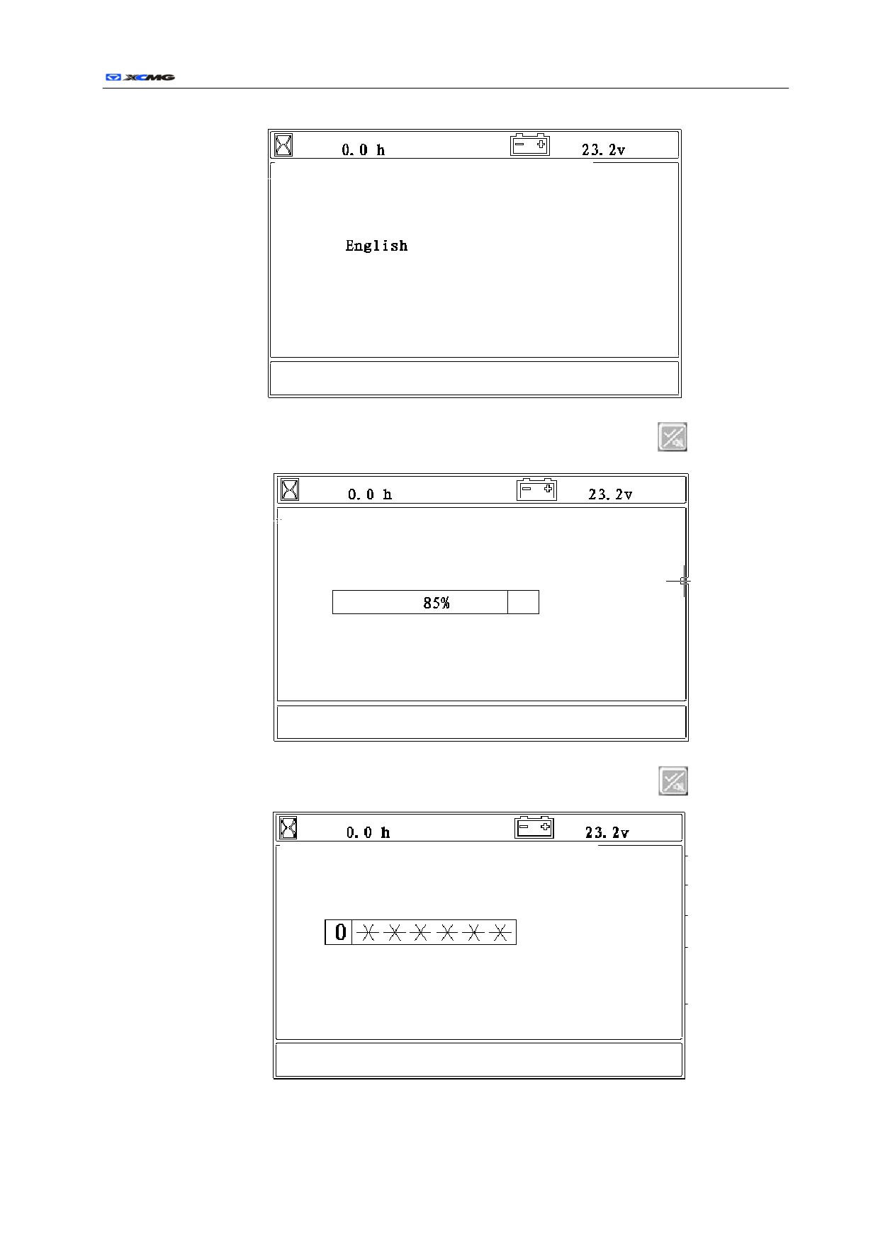
¾ Choose in the user setting menu and press the confirmation key
, the clock
adjustment menu is entered as follows:
Set up clock
Date:
Time:
Date time and information display area
¾ Choose in the user setting menu and press the confirmation key
, the clock
adjustment menu is entered as follows:
r
59
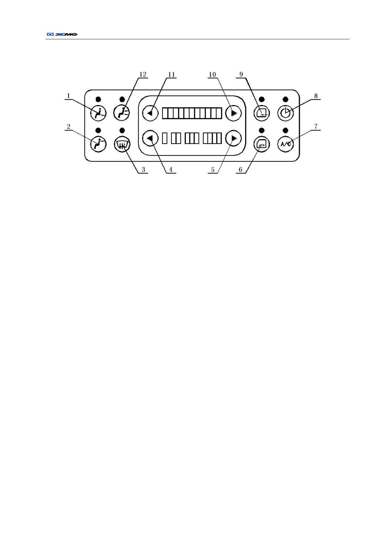
Language setup
Chinese
Date time and information display area
¾ Choose in the user setting menu and press the confirmation key
, the language
setting menu is entered as follows:
Brightness control
Date time and information display area
¾ Choose in the user setting menu and press the confirmation key
, system setting
use menu is entered as follows:
Password input
Date time and information display area
XE210/XE230/XE260C Hydraulic Excavator
60
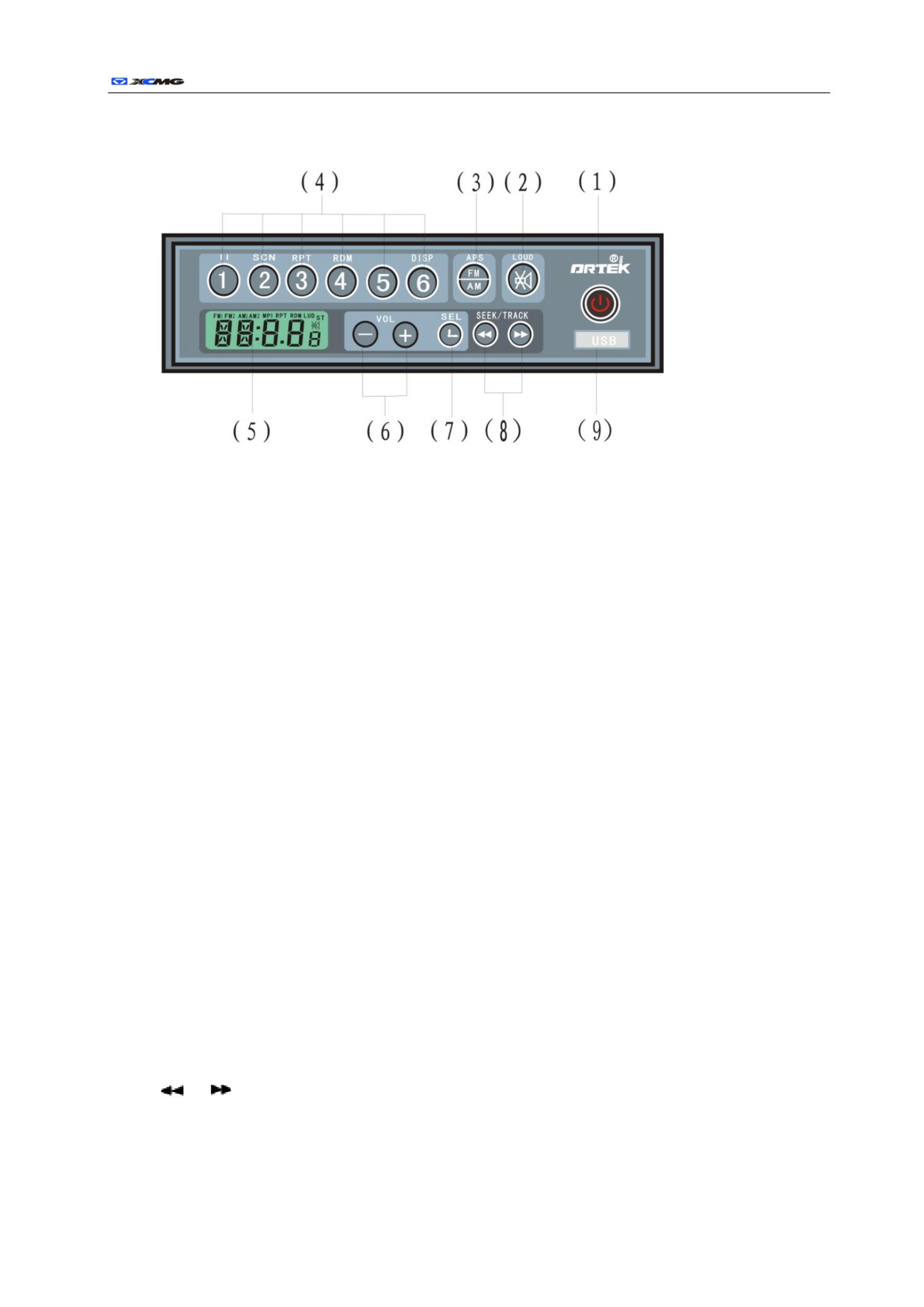
Control panel of Air Conditioner
1.
Control Button of Air-out (Foot direction)
When this button is pressed, the motor of foot direction part of air conditioning unit is started and the
ventilation door is opened to have the air blown out from the lower air duct.
2.
Control Button of Air-out (Face direction)
When this button is pressed, the motor of face direction part of air conditioning unit is started, the
ventilation door is opened to have the air blown out from the upper air duct.
3.
Control Button for Defrostation
When this button is pressed, the warm air passes through the air duct and directly blows towards the
window in front of the driver.
4.
Air Volume Regulation Button (Small)
When this button is pressed, the indicator light for air volume is on; the air volume shifts from high to
low (the volume is from level 4 to 3, and from 2 to 1).
5.
Air Volume Regulation Button (Large)
When this button is pressed, the indicator light for air volume is on; the air volume shifts from low to
high (the volume is from level 1 to 2, and from 3 to 4).
6.
Control Switch for Internal Ventilation
When this button is pressed, the fresh air motor of air conditioning unit is off while other motors are
started, and then the air inside the cab is transmitted to the inner of the unit through evaporator blower,
and then the air is transmitted into the cab by the evaporator blower to form ventilation.
7.
Cooling Switch
When this button is pressed, the cooling indicator is on and the air conditioning system is switched to
the cooling mode.
8.
Power Switch
When this button is pressed, the indicator of control panel is on; the control panel is powered on, and
the system is switched to operation mode.
9.
Control Button for Fresh Air Ventilation
When this button is pressed, the motor for fresh air of air conditioning unit motor starts, and then the
fresh air from outside fills into the cab and fresh the stale air inside.
10.
Temperature Adjustment Button (Large)
When this button is pressed, the temperature indicator light is on, the temperature is adjusted from
low to high; when it hits 30℃, the air-conditioning automatically converts from cold air to warm air.
11.
Temperature Adjustment Button (Small)
When this button is pressed, the temperature indicator light is on, and the temperature is adjusted from
high to low.
12.
Air Direction Control Button ( Face & Foot Direction )
When this button is pressed, all motors of air conditioning unit is started to have the air blown out
from the wind duct freely.
r
61
Radio
(1) Power/mode switch
◇Press the button to switch on power; hold the button under the working state to turn off the radio.
◇When the radio is powered on, press the button to toggle between FMÙ MP3 (Ù IN Optional).
(Press: less than 2 sec.; hold: over2 sec.)
(2) Mute/Auto volume
◇Press to toggle mute on/off.
◇Hold to toggle auto volume on/off
(3) Band switch/auto tuning
◇Press to switch among FM1/ FM2/AM1/ AM2.
◇Hold to detect and store new stations available in the preset
(4) Preset Button
◇In FM mode, press to select preset station and hold to store station.
◇In MP3 mode,
<1/PAUSE>
Pause/play.
<2/SCN>
Scan/ normal play.
<3/RPT>
Repeat/ normal play.
<4/RDM>
Random/ normal play.
<6/DISP>
Display track number/duration.
(5) Screen
(6) VOL+/- Volume
Press VOL+/- to turn up or down the volume.
(7) SEL Effect/Time setting
◇Press to display time and date on screen; press within 5 seconds to view effect settings
◇In time display, hold to reset time
◇Display returns to screen information if no button is pressed within 5 seconds
(8)
/
FM scan & MP3 file selection
◇In FM mode, press to change frequency forward or backward
◇In mp3 mode, press to select files
(9) USB.
r
62
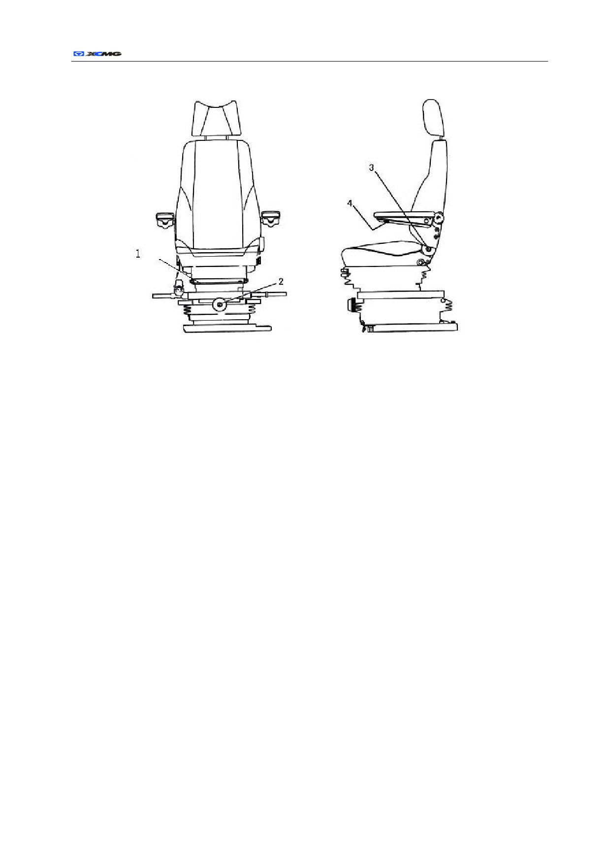
Seat
1. Adjustable back and forth
2. Adjustable on weight
3. Adjustable back cushion
4. Adjustable armrests
Warning!
z
The seat is designed for one person at a time.
z
Do not adjust the seat during digging actions.
z
Avoid moving objects.
z
Assembly and maintenance should be performed by qualified personnel.
r
63
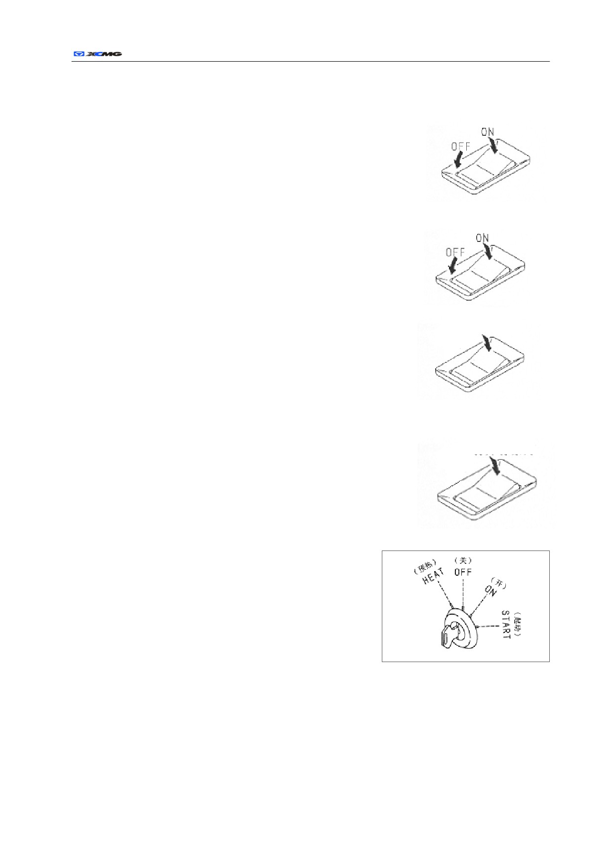
Switches
Lighting switch
Rocker Switch 1#
Press this switch (1#), the illuminating lamps for the movable arm
and the platform are turned on.
Switch for the windshield wiper
Rocker Switch 2#.
Press this switch (2#), the windshield wiper for the front
glass
Swing continuously.
Switch for the watching window wiper
Water injection
Rocker Switch 3#.
Press this switch (3#) continuously, the cleaning solution of the window is
sprayed on the front glass, when releasing, spraying stops.
Switch for the background lights of the air conditioner
and radio
Rocker Switch 4#.
Turn on backlight
Press this switch (4#) continuously, the cleaning solution of the
window is sprayed on the front glass, when releasing, spraying stops.
Starting switch
The switch is use for starting or shutting down the engine.
OFF position
The key can be plugged in and pulled out. All of the switches of the
electric system are closed. The engine is stopped.
ON position
When the engine is running, keep the key of the starting switch in
the ON position.
START position.
This is the starting position for the engine. When starting the engine,
keep the key in this position. After the engine is started, release the
key immediately and the key will come back to the ON position automatically.
HEAT (preheating) position
When starting the engine in winter, adjust the key to this position. When the key is adjusted to the HEAT
position, the preheating monitor is on. The key is in this position until the lamp of the monitor is shining.
After the lamp of the preheating monitor is shining, release the key immediately and the key will come back
to the OFF position automatically. And then turn the key to the START position and start the engine.