Hyundai Excavator R450LC-7. Service and repair manual - page 26


  Index      Manuals     Hyundai Excavator R450LC-7. Service and repair manual


Search            copyright infringement  


Content      ..     24      25      26      27     ..


Hyundai Excavator R450LC-7. Service and repair manual - page 26


8-35-6

DISASSEMBLY

Select place suitable to disassembling.
Select clean place.
Spread  rubber sheet,  cloth or so  on on
overhaul workbench top to prevent parts
from being damaged.

Remove dust, rust, etc, from pump
surfaces with cleaning oil or so on.

Remove drain port plug(468) and let oil
out of pump casing(Front and rear pump).

3)

Loosen hexagon socket head bolts(402)
which tighten swash plate support(251),
pump casing(271) and valve cover(R,
312).

(1)


(2)

(3)

(6)

Loosen hexagon socket head bolts(401)
which tighten swash plate support(251),
pump casing(271) and valve cover(F,
311).
If gear pump and so on are fitted to rear
face of pump, remove them before
starting this work.

(5)

Remove hexagon socket head bolts(412,
413) and remove regulator.

(4)

36078MP02

8-35-7

Place pump horizontally on workbench
with its regulator-fitting surface down, and
separate pump casing(271) from valve
cover(F, 311).
Before bringing this surface down, spread
rubber sheet on workbench without fail to
prevent this surface from being damaged.

(7)

Separate valve cover(F, 311) from valve
cover(R, 312) and pull out booster(130),
spline coupling(114).

Separate valve cover(R, 312) from pump
casing and then pull out the cylinder
block(012) of pump casing(271) straightly
over drive shaft(R, 113).    Pull out also
pistons(151),  set plate(153), spherical
bush(156) and cylinder springs (157)
simultaneously.

Take care not to damage sliding surfaces
of  cylinder,  spherical  bushing,  shoes,
swash plate, etc.

(8)

(9)

Remove hexagon socket head bolts(406)
and then seal cover(F, 261).
Fit bolt into pulling-out tapped hole of seal
cover(F), and cover can be removed
easily.
Since oil seal is fitted on seal cover(F),
take care not to damage it when removing
cover.

(10)

36078MP03

36078MP04

36078MP05

8-35-8

Tapping lightly fitting flange section of
swash plate support(251) on its pump
casing side, separate swash plate support
from pump casing.

(11)

Remove shoe plate(211) and swash
plate(212) from pump casing(271).

(12)

Tapping lightly shaft ends of drive
shafts(111, 113) with plastic hammer, take
out drive shafts from swash plate supports.

(13)

36078MP06

36078MP07

36078MP08

8-35-9

Remove valve plates(313, 314) from valve
cover(311, 312).
These may be removed in work 7, 9.

If necessary, remove stopper (L, 534),
stopper(S, 535), servo piston(532) and
tilting pin(531) from pump casing(271),
and needle bearing(124) from valve
cover(311, 312).
In removing tilting pin, use a protector to
prevent pin head from being damaged.
Since loctite is applied to fitting areas of
tilting pin and servo piston, take care not
to damage servo piston.
Do not remove needle bearing as far as
possible, except when it is considered to
be out of its life span.
Do not loosen hexagon nuts of valve
cover and swash plate support.
If loosened, flow setting will be changed.

This is the end of disassembling procedures.

(14)

(15)

(16)

36078MP09

8-35-10

ASSEMBLY

For reassembling reverse the disassem-
bling procedures, paying attention to the
following items.

Do not fail to repair the parts damaged
during disassembling, and prepare
replacement parts in advance.
Clean each part fully with cleaning oil
and dry it with compressed air.
Do not fail to apply clean working oil to
sliding sections,  bearings,  etc. before
assembling them.
In principle, replace seal parts, such as
O-rings, oil seals, etc.
For fitting bolts, plug, etc., prepare a
torque wrench or so on, and tighten them
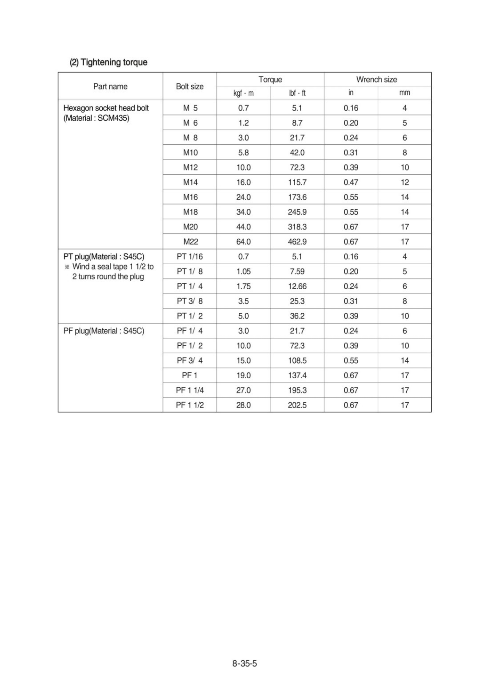
with torques shown in page 8-11, 12.
For the double-pump, take care not to
mix up parts of the front pump with those
of the rear pump.

(1)

4)

Fit swash plate support(251) to pump
casing(271),  tapping the former  lightly
with  a hammer.
After servo piston, tilting pin, stopper(L)
and stopper(S) are removed, fit them
soon to pump casing in advance for
reassembling.
In tightening servo piston and tilting pin,
use a protector to prevent tilting pin head
and feedback pin from being damaged.
In addition, apply loctite(Medium strength)
to their threaded sections.

(2)

36078MP10

8-35-11

Place pump casing with its regulator fitting
surface down, fit tilting bush of swash
plate to tilting pin(531) and fit swash plate
(212) to swash plate support(251)
correctly.
Confirm  with fingers  of both hands  that
swash plate can be removed smoothly.
Apply grease to sliding sections of swash
plate and swash plate support, and drive
shaft can be fitted easily.

(3)

Assemble piston cylinder subassembly

cylinder block(012), piston subassembly

(151, 152), set plate(153), spherical
bushing(156) and cylinder spring (157)

.

Fit spline phases of retainer and cylinder.
Then, insert piston cylinder subassembly
into pump casing(271).

(6)

Assemble seal cover(F, 261) to pump
casing(271) and fix it with hexagon socket
head bolts(406).
Apply grease lightly to oil seal in seal
cover(F).
Assemble oil seal, taking full care not to
damage it.
For tandem type pump, fit rear cover(263)
and seal cover(262) similarly.

(5)

To swash plate support(251), fit drive
shaft(111) set with bearing(123), bearing
spacer(127) and snap ring(824).
Do not tap drive shaft with hammer or so
on.
Assemble them into support, tapping
outer race of bearing lightly with plastic
hammer.
Fit them fully, using steel bar or so on.

(4)

36078MP11

36078MP12

36078MP13

36078MP14

8-35-12

Fit valve plate(313) to valve cover(F, 311),
and fit valve plate(314) to valve cover(R,
312), entering pin into pin hole.
Take care not to mistake suction / delivery
directions of valve plate.

(7)

Fit valve cover(F, 311) to valve cover(R)
and tighten hexagon socket head
bolts(402).

(9)

Fit valve block(R, 312) to pump casing
(271) and fit spline coupling(114) and
booster(130) to shaft(R, 113).
Take care not to mistake direction of valve
cover.
Fit valve cover with regulator up and with
delivery flange left, viewed from front side.
Take care not to mistake direction of
booster(130).
(Refer to the sectional drawing)

(8)

Fit pump casing(271) with shaft(F, 111) to
valve cover(F, 311) and tighten hexagon
socket head bolts(401).
Mate spline phases of shaft(F) and spline
coupling, with shaft(F) been rotating.

(10)

36078MP15

36078MP16

36078MP18

8-35-13

Putting feedback pin of tilting pin into
feedback lever of regulator, fit regulator
and tighten hexagon socket head
bolts(412,413).
Take care not to mistake regulator of front
pump for that of rear pump.

Fit drain port plug(468).

(11)

(12)

This  is  the  end  of  reassembling procedures.

36078MP17

8-35-17

Tightening torque

(2)

8-35-18

DISASSEMBLY
Since the regulator consists of small
precision finished parts, disassembly and
assembly are rather complicated.
For this reason, replacement of a regulator
assembly is recommended, unless there is
a special reason, but in case disassembly is
necessary for an unavoidable reason, read
through this manual to the end before
starting disassembly.

Choose a place for disassembly.
Choose a clean place.
Spread rubber sheet, cloth, or so on on
top of work-bench to prevent parts from
being damaged.

Remove dust,  rust,  etc. from surfaces  of
regulator with clean oil.

(1)


(2)

3

3

)

Remove hexagon socket head screw
(438) and remove cover(C,629)
Cover(C) is fitted with adjusting screw
(C,QI) (628, 925), adjusting ring(C, 627),
lock nut(630), hexagon nut(801) and
adjusting screw(924).
Do not loosen these screws and nuts.
If they are loosened, adjusted pressure-
flow setting will vary.

(4)

Remove hexagon socket head screw
(412, 413) and remove regulator main
body from pump main body.
Take care not to lose O-ring.

(3)

REG01 (210-7)

REG02 (210-7)

8-35-19

Remove locking ring(858) and take out
fulcrum plug(614) and adjusting plug
(615).
Fulcrum plug(614) and adjusting plug
(615) can easily be taken out with M6 bolt.

(8)

Remove snap ring(814) and take out
spring seat(653), return spring(654) and
sleeve(651).
Sleeve(651) is fitted with snap ring(836).
When removing snap ring(814), return
spring(654) may pop out.
Take care not to lose it.

(7)


Remove hexagon socket head screws
(436, 438) and remove pilot cover(641).
After removing pilot cover, take out set
spring(655) from pilot section.

(6)

After removing cover(C, 629) subassemb-
ly, take out outer spring(625), inner spring
(626) and spring seat(C, 624) from
compensating section. 
Then draw out adjusting ring(Q, 645), pilot
spring(646) and spring seat(644) from
pilot section.
Adjusting ring(Q,645) can easily be drawn
out with M4 bolt.

(5)

REG03 (210-7)

REG04 (210-7)

REG05 (210-7)

REG06 (210-7)

8-35-20

Draw out pin(874) and remove feedback
lever(611).
Push out pin(874, 4mm in dia.) from above
with slender steel bar so that it may not
interfere with lever(1, 612).

(10)

Remove lever(2, 613).   Do not draw out
pin(875).
Work will be promoted by using pincers or
so on.

(9)

REG07 (210-7)

REG08 (210-7)

REG09 (210-7)

REG10 (210-7)


Content      ..     24      25      26      27     ..