Hyundai Excavator R450LC-7. Service and repair manual - page 25
 

  Index      Manuals     Hyundai Excavator R450LC-7. Service and repair manual


Search            copyright infringement  


Content      ..     23      24      25      26     ..


Hyundai Excavator R450LC-7. Service and repair manual - page 25


8-24

Putting feedback pin of tilting pin into
feedback lever of regulator, fit regulator
and tighten hexagon socket head cap
screws(412, 413).
Since the regulators on the drive shaft
side and the driven shaft side are set at
different pressure and flow values, take
care not to mistake one for another.

(16)

45078MP22

45078MP27

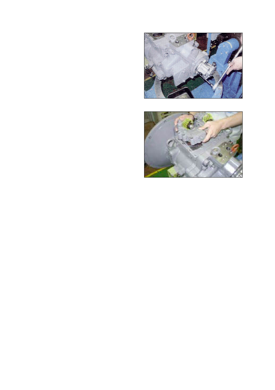
Fit booster(130), booster cover(131)
cover(262) and gear pump.

(15)

8-28

Tightening torque

(2)

8-29

DISASSEMBLY
Since the regulator consists of small
precision finished parts, disassembly and
assembly are rather complicated.
For this reason, replacement of a regulator
assembly is recommended, unless there is
a special reason, but in case disassembly is
necessary for an unavoidable reason, read
through this manual to the end before
starting disassembly.

Choose a place for disassembly.
Choose a clean place.
Spread rubber sheet, cloth, or so on on
top of work-bench to prevent parts from
being damaged.

Remove dust,  rust,  etc. from surfaces  of
regulator with clean oil.

(1)


(2)

3

3

)

Remove hexagon socket head screw
(438) and remove cover(C,629)
Cover(C) is fitted with adjusting screw
(C,QI) (628, 925), adjusting ring(C, 627),
lock nut(630), hexagon nut(801) and
adjusting screw(924).
Do not loosen these screws and nuts.
If they are loosened, adjusted pressure-
flow setting will vary.

(4)

Remove hexagon socket head screw
(412, 413) and remove regulator main
body from pump main body.
Take care not to lose O-ring.

(3)

REG01 (210-7)

REG02 (210-7)

8-30

Remove locking ring(858) and take out
fulcrum plug(614) and adjusting plug
(615).
Fulcrum plug(614) and adjusting plug
(615) can easily be taken out with M6 bolt.

(8)

Remove snap ring(814) and take out
spring seat(653), return spring(654) and
sleeve(651).
Sleeve(651) is fitted with snap ring(836).
When removing snap ring(814), return
spring(654) may pop out.
Take care not to lose it.

(7)


Remove hexagon socket head screws
(436, 438) and remove pilot cover(641).
After removing pilot cover, take out set
spring(655) from pilot section.

(6)

After removing cover(C, 629) subassemb-
ly, take out outer spring(625), inner spring
(626) and spring seat(C, 624) from
compensating section. 
Then draw out adjusting ring(Q, 645), pilot
spring(646) and spring seat(644) from
pilot section.
Adjusting ring(Q,645) can easily be drawn
out with M4 bolt.

(5)

REG03 (210-7)

REG04 (210-7)

REG05 (210-7)

REG06 (210-7)

8-31

Draw out pin(874) and remove feedback
lever(611).
Push out pin(874, 4mm in dia.) from above
with slender steel bar so that it may not
interfere with lever(1, 612).

(10)

Remove lever(2, 613).   Do not draw out
pin(875).
Work will be promoted by using pincers or
so on.

(9)

REG07 (210-7)

REG08 (210-7)

REG09 (210-7)

REG10 (210-7)

8-32

Remove lever(1, 612).  Do not draw out
pin(875).

Draw out pilot piston(643) and spool(652).

Draw out piston case(622), compensating
piston(621) and compensating rod(623).
Piston  case(622) can  be taken out  by
pushing compensating rod(623) at
opposite side of piston case.

This completes disassembly.

(11)

(12)

(13)

8-33

ASSEMBLY

For assembly, reverse disassembly
procedures, but pay attention to the
following items.

Always repair parts that were scored at
disassembly.
Get replacement parts ready before-
hand.
Mixing  of  foreign  matter  will   cause
malfunction.
Therefore, wash parts well with cleaning
oil, let them dry with jet air and handle
them in clean place.
Always tighten bolts, plugs, etc.   to their
specified torques.
Do  not  fail to coat  sliding  surfaces  with
clean hydraulic oil before assembly.
Replace seals such as O-ring with new
ones as a rule.

(1)

4

4

)

Put compensating rod(623) into compen-
sating hole of casing(601).

Put pin force-fitted in lever(1, 612) into
groove of compensating rod and fit lever
(1) to pin force-fitted in casing.

(2)

(3)

Fit spool(652) and sleeve(651) into hole in
spool of casing.
Confirm that spool and sleeve slide
smoothly in casing without binding.
Pay attention to orientation of spool.

(4)

8-34

Lever (1) side

Lever (2) side

(Fulcrum plug of

adjusting plug side)

Fit return spring(654) and spring seat
(653) into spool hole and attach snap ring
(814).

(10)

Fit fulcrum plug(614) so that pin force-
fitted in fulcrum plug(614) can be put into
pin hole of lever(2).  
Then fix locking ring(858).

Insert adjusting plug(615) and fit locking
ring.
Take care not to mistake inserting holes
for fulcrum plug and adjusting plug.
At this point in time move feedback lever
to confirm that it has no large play and is
free from binding.

(8)

(9)

Put pilot piston(643) into pilot hole of
casing.
Confirm that pilot piston slides smoothly
without binding.

Put pin force-fitted in lever(2, 613) into
groove of pilot piston.
Then fix lever(2).

(6)

(7)

Fit feedback lever(611), matching its pin
hole with pin hole in spool.
Then insert pin(874).
Insert pin in feedback lever a little to ease
operation.
Take care  not to mistake  direction  of
feedback lever.

(5)

8-27 (210-7)

REG11 (210-7)

REG12 (210-7)

REG13 (210-7)

8-35

Install cover(C, 629) fitted with adjusting
screws(628, 925), adjusting ring(C, 627),
lock nut(630), hexagon nut(801) and
adjusting screw(924).
Then tighten them with hexagonal socket
head screws(438).

This completes assembly.

(13)

Put spring seat(644), pilot spring(646) and
adjusting ring(Q, 645) into pilot hole.
Then fix spring seat(624), inner spring
(626) and outer spring(625) into compen-
sating hole.
When fitting spring seat, take care not to
mistake direction of spring seat.

(12)

Fit set spring(655) to spool  hole and  put
compensating piston(621) and piston
case(622) into compensating hole.
Fit pilot cover(641) and tighten it with
hexagonal socket head screws(436, 438).

(11)

REG14 (210-7)

RE15 (210-7)

REG16 (210-7)

1.  REMOVAL AND INSTALL

REMOVAL 

Lower the work equipment to the ground
and stop the engine.

Loosen the breather slowly to release the
pressure inside the hydraulic tank.
Escaping  fluid  under  pressure  can
penetrate  the  skin  causing  serious
injury.

Loosen the drain plug under the hydraulic
tank and drain the oil from the hydraulic
tank.

·

Hydraulic tank quantity : 250

Remove socket bolts(5) and disconnect
hose (1,2).

Disconnect pilot line hoses(4, 5, 6, 7, 8, 9,
10, 11).

Remove bolts(4) and disconnect pump
suction tube (3).
When pump suction tube is disconnected,
the oil inside the piping will flow out, so
catch it  in oil pan.

Sling the pump assembly and remove the
pump mounting bolts.

·

Weight : 180kg(400lb)

Pull out the pump assembly from housing.
When removing the pump assembly,
check that all the hoses have been
disconnected.

8-35-1

G

GROUP  3  PUMP DEVICE(#0464~)

1

2

5

3

4

5

6

7

8

9

10

A2

11

1)

(1)

(2)

(3)

(4)

(5)

(6)

(7)

50078MP01

50078MP02

13031GE18

8-35-2

INSTALL 

Carry out installation in the reverse order
to removal

Remove the suction strainer and clean it.

Replace the return filter with a new one.

Remove breather and clean it.

After adding oil to the hydraulic tank to the
specified level.

Bleed the air from the hydraulic pump.

Remove the air vent plug(2EA)
Tighten plug lightly
Start the engine, run at low idling, and
check oil come out from plug.
Tighten plug.

Start the engine, run at low idling(3~5
minutes) to circulate the oil through the
system.

Confirmed the hydraulic oil level and
check the hydraulic oil leaks or not.

2)

(1)

(2)

(3)

(4)

(5)

(6)


(7)

(8)


Content      ..     23      24      25      26     ..