SANY Crawler Hydraulic Excavator (SY195C9, SY205C9, SY215C9, SY225C9). Shop Manual (2013) - page 26
Disassembly and Assembly
8.3 Start Motor AS - Remove and Install
8.3.1 Removal
CAUTION
Ɣ Before removing the start motor assem-
bly, disconnect the cable from the nega-
tive (-) post of the battery, and insulate
between the cable and the negative post
with insulation tape.
1. Open the engine hood.
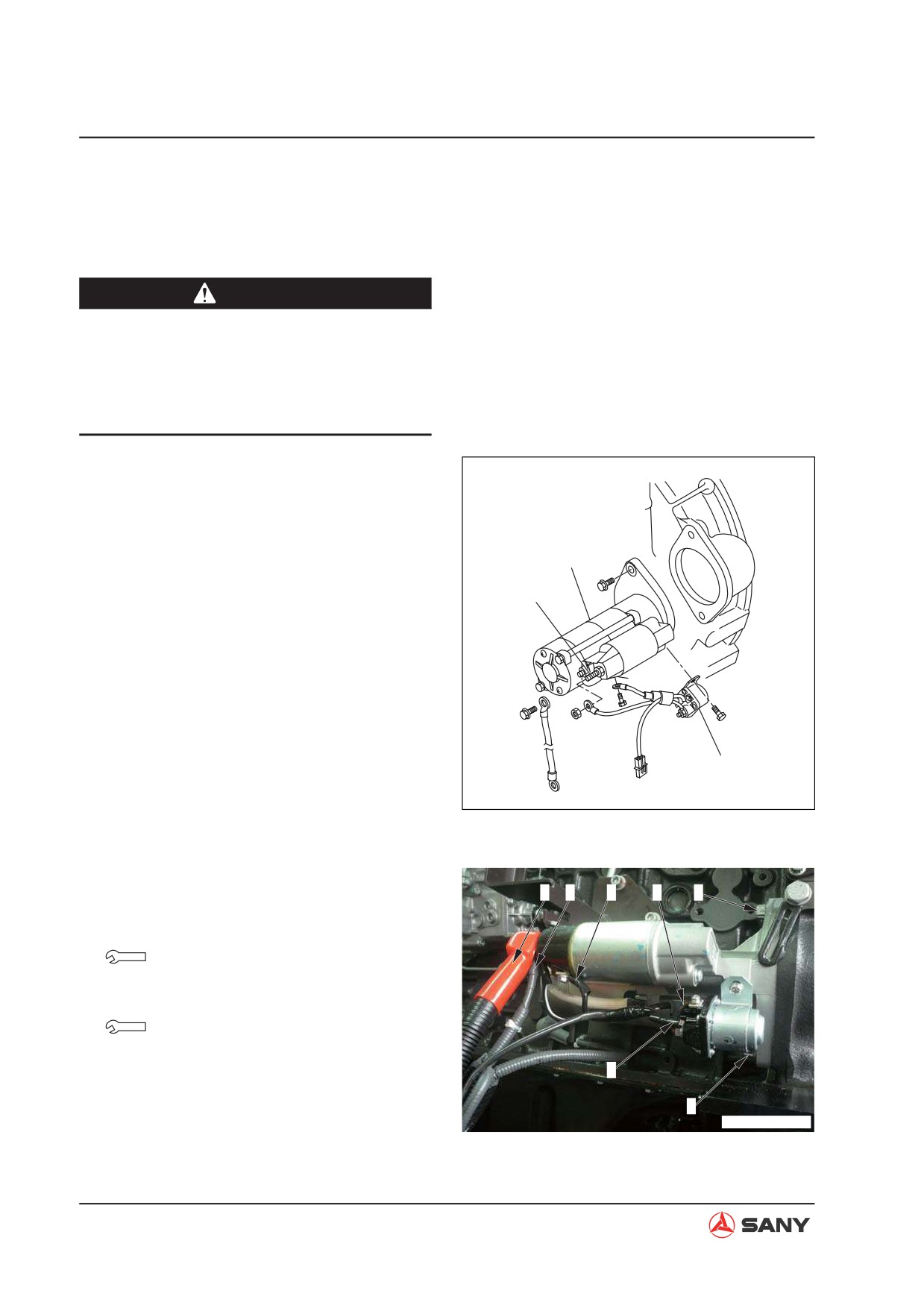
2. Disconnect the cables (1), (2), (3), (4) and
(5).
3. Unscrew the bolts (6) and (7) used to fix
Starter
the start motor. Remove the start motor as-
Terminal B
sembly.
Terminal S
Starter relay
ZX215-1006001
8.3.2 Installation
1
2
3
4
6
Ɣ Installation is to be performed in the re-
verse order of removal.
Terminal B locknut (start motor):
18 ~ 25 N·m {1.8 ~ 2.6 kgf·m}
Fixing bolts (start motor):
43±6 N·m {4.4±0.6 kgf·m}
5
7
ZX215T-1006002
8-10
Disassembly and Assembly
8.4 Injection Pump AS - Remove and Install
8.4.1 Removal
CAUTION
Ɣ Disconnect the negative (-) post of the
battery.
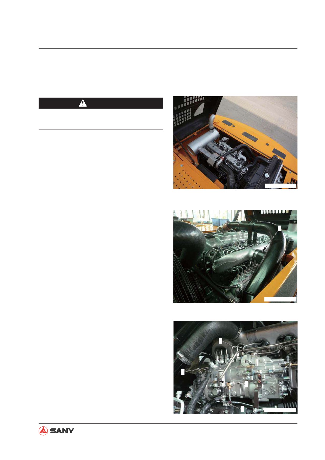
1. Open the engine hood.
ZX215T-1006003
2. Disconnect the air intake hose (1).
1
ZX215T-1006004
3. Disconnect fuel supply tube (2), fuel deliv-
ery hose (4), fuel return hose (3) and fuel
supply tube (5).
5
Ɣ Block the hose with a cork in order to
prevent flow of fuel from the hose.
3
2
4
ZX215T-1006005
8-11
Disassembly and Assembly
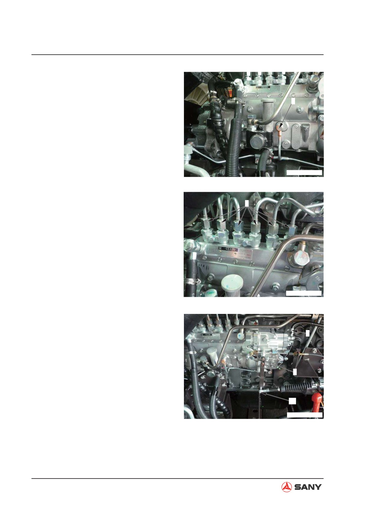
4. Disconnect the lubrication tube (6).
6
ZX215T-1006006
5. Disconnect six fuel delivery tubes (7).
7
ZX215T-1006007
6. Disconnect the air hose (8).
7. Remove the bolt (9) fixing the electronic
8
choke. Disconnect the bolt (10) fixing the
governor motor.
9
10
ZX215T-1006008
8-12
Disassembly and Assembly
8. Adjust the injection timing of the timing
gear. For more information, see “Fuel In-
jection Timing - Test and Adjust” on page 6-13.
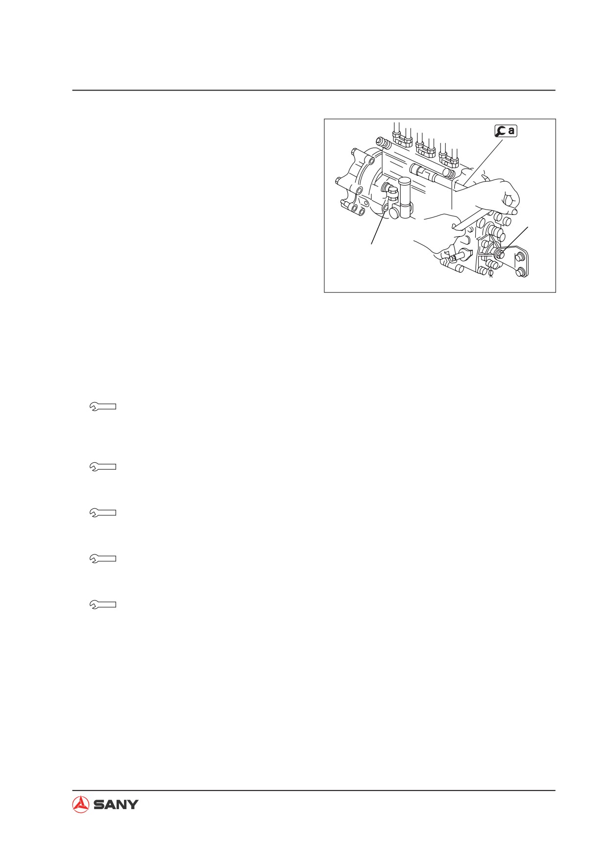
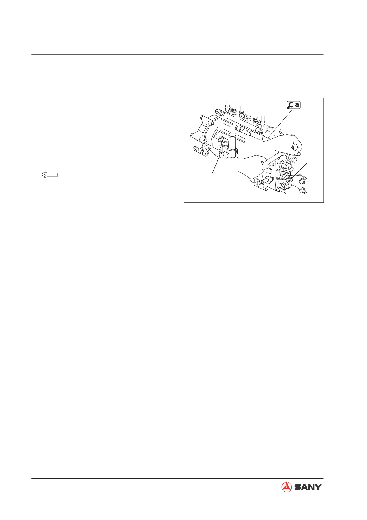
9. Remove the injection pump mounting nuts
in order to disassemble the injection pump
assembly.
B
A: 4 nuts on the flange
A
B: 1 nut
ZX215-1006009
8.4.2 Installation
Ɣ
Installation is to be performed in the re-
verse order of removal.
Bolts for installation of fuel supply
tube:
20~29 N·m {2.1~3.0 kgf·m}
Relief valve:
20~29 N·m {2.1~3.0 kgf·m}
Bolts for installation of engine oil line:
10~13 N·m {1.0~1.3 kgf·m}
Fuel injection tube:
24 N·m {2.5 kgf·m}
Bolts for installation air hose:
12~15 N·m {1.2~1.5 kgf·m}
Ɣ Adjust the engine speed. For more in-
formation, see “Engine Speed - Test
and Calibrate” on page 6-3.
8-13
Disassembly and Assembly
Ɣ Installation of the fuel injection pump is to
be performed as the following:
1) Check the fuel injection timing to see if it
has been adjusted properly.
Ɣ For more information, see “Fuel Injec-
tion Timing - Test and Adjust” on page 6-13.
2) Assemble the fuel injection pump assem-
bly and tighten the 4 nuts at position A and
1 nut at position B.
B
Nut: 9.8±2 N·m {10±0.2 kgf·m}
A
Ɣ Air bleeding
ZX215-1006009
Bleed the air from the fuel injection system.
8-14
Disassembly and Assembly
8.5 Engine Front Seal - Remove and Install
8.5.1 Removal
1. Remove the radiator assembly.
For more information, see “Radiator AS -
Remove and Install” on page 8-24.
Water pump
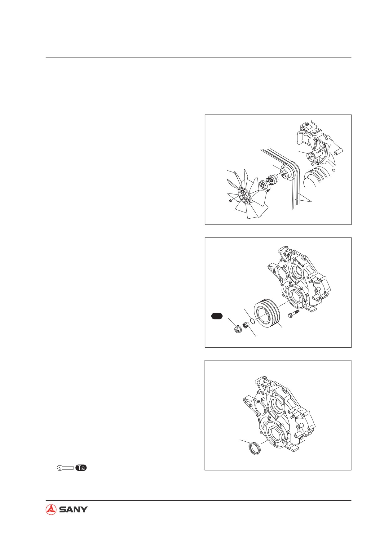
2. Remove the engine fan (1), the belt (2) and
the pulley (3).
3
1
2
ZX215-1006010
3. Remove the mounting nut (4) and replace
the cone (5) and the O-ring (6). Remove
the crankshaft belt pulley (7).
6
Ta 4
7
5
ZX215-1006011
4. Disassemble the front oil seal (8).
8.5.2 Installation
8
Ɣ Installation is to be performed in the re-
verse order of removal.
ZX215-1006012
Nut: 490 N·m {50 kgf·m}
8-15
Disassembly and Assembly
8.6 Engine Rear Seal - Remove and Install
8.6.1 Removal
1. Remove the hydraulic pump assembly.
For more information, see “Hydraulic Pump
AS - Remove and Install” on page 8-85.
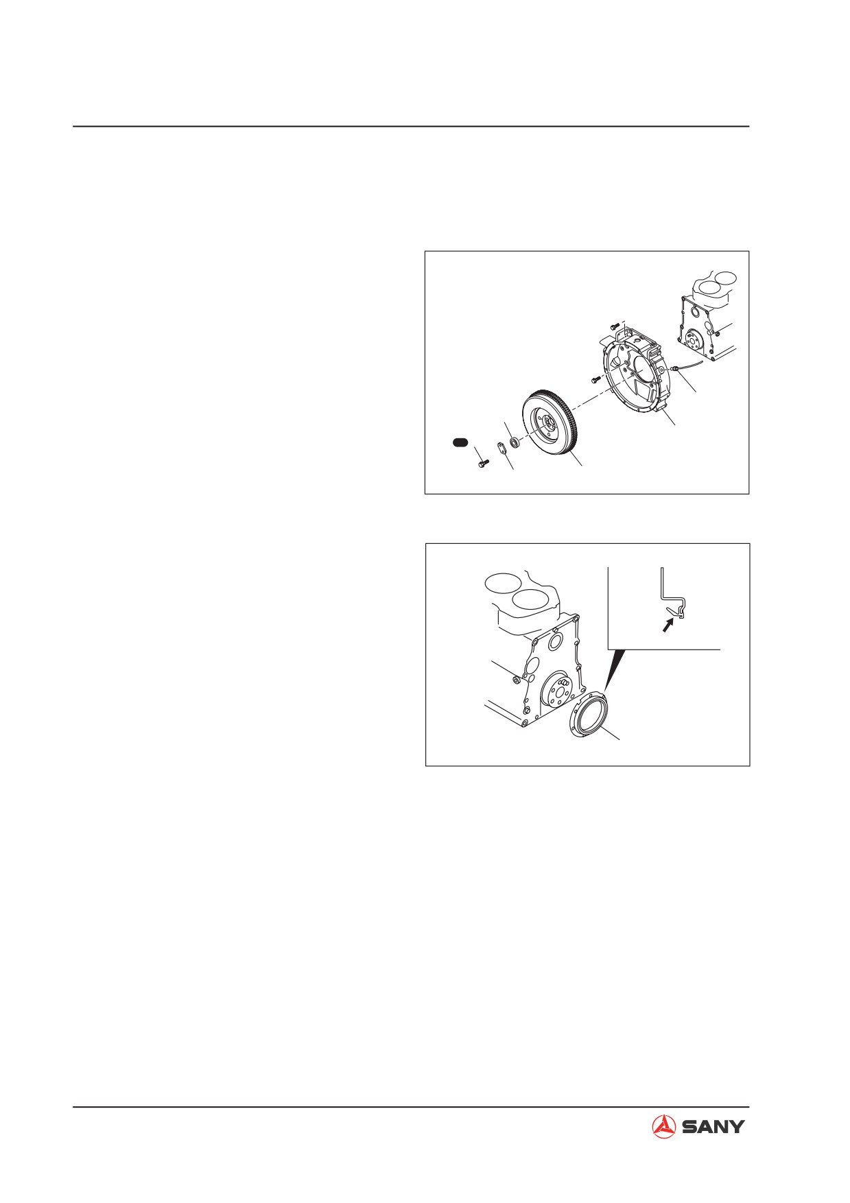
2. Remove the bolt (1), the latch piece (2)
and the bearing (3).
3. Remove the flywheel (4).
5
3
4. Remove the engine speed sensor (5) and
6
Ta 1
the flywheel shell (6).
4
2
ZX215-1006013
5. Remove the rear seal (7).
Lip
7
ZX215-1006014
8-16
Disassembly and Assembly
8.6.2 Installation
Ɣ The installation is to be performed in the
reverse order of removal.
Bolt:
39 N·m {4.0 kgf·m} + 47°
Sealant
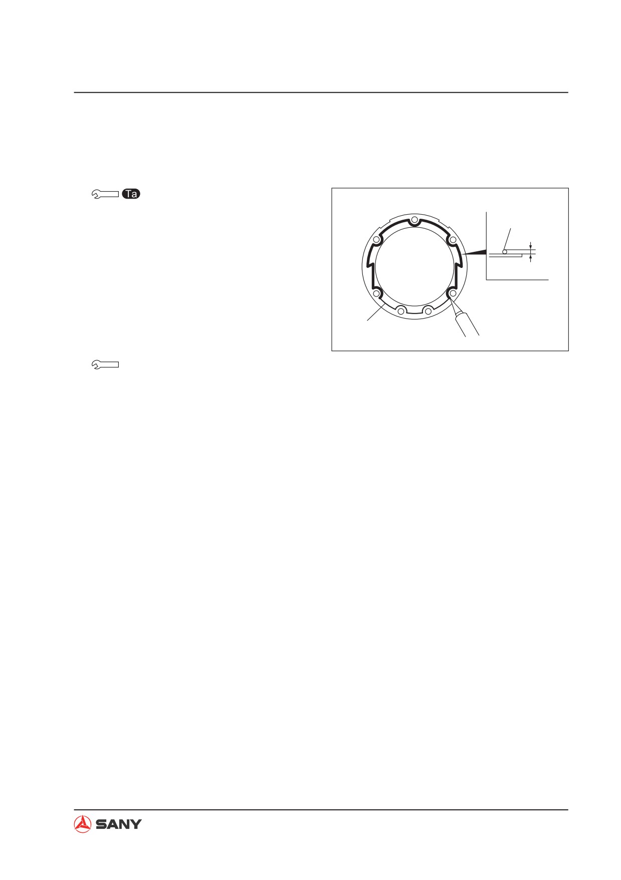
Ɣ The rear oil seal is to be installed accord-
ing to the following procedure:
ø2mm
1. Apply engine oil to the lips of the rear seal.
2. Clean the oil-sealing surface.
3. Apply the sealant evenly and continuously
Line
align the line of the rear seal.
ZX215-1006015
Sealant (Tonsun 1596)
4. The installation is to be performed 3 min-
utes after application of the sealant. Be
careful not to deviate the line while apply-
ing the sealant.
8-17
Disassembly and Assembly
8.7 Cylinder Head AS - Remove and Install
8.7.1 Removal
CAUTION
Ɣ Disconnect the negative (-) post of the
battery.
1. Drain the engine of coolant.
Coolant: 18 L
2. Open the engine hood.
ZX215T-1006016
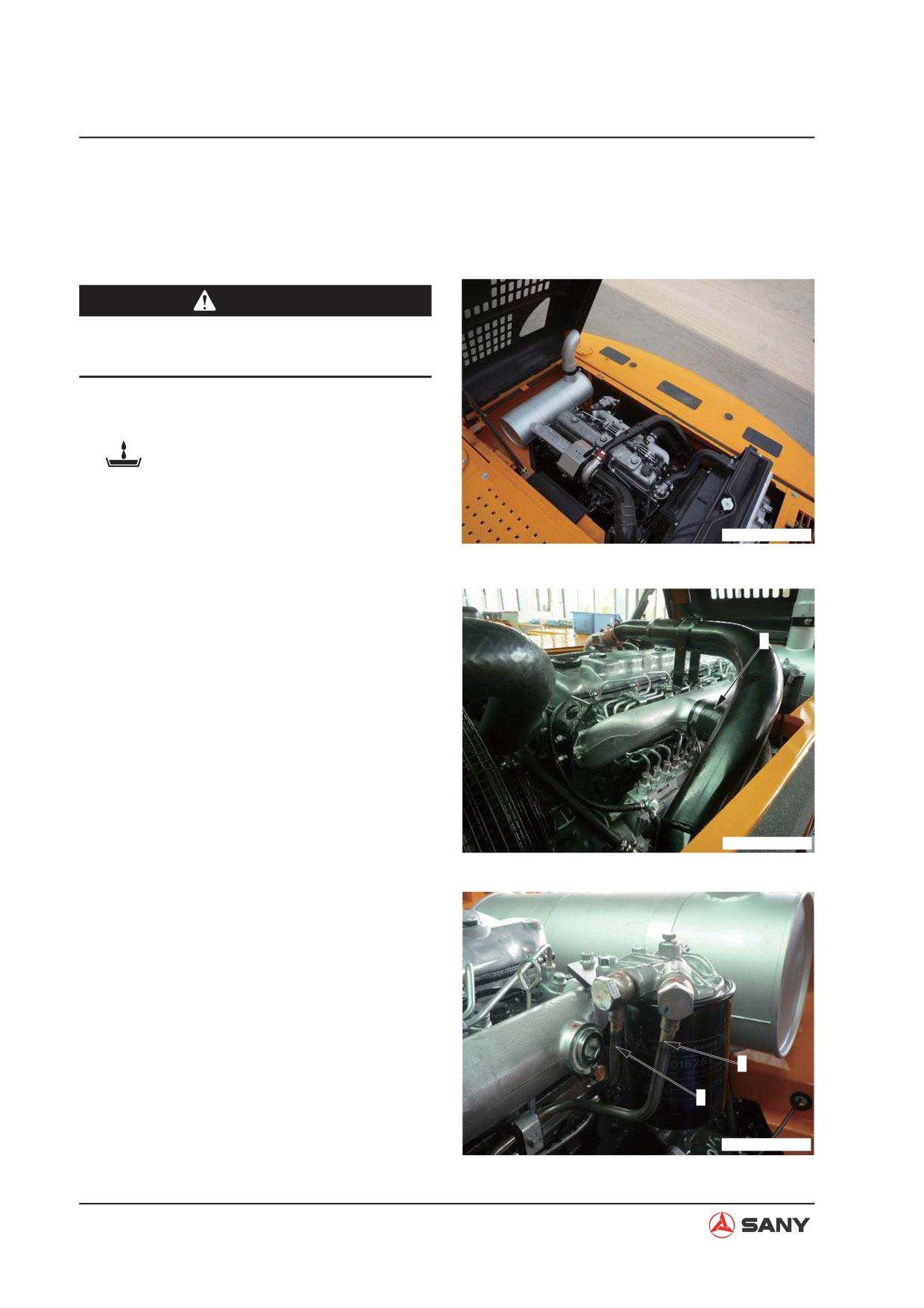
3. Disconnect the air intake hose (1).
1
ZX215T-1006017
4. Remove piping (2) and piping (3) between
the fuel filter and the injection pump.
3
2
ZX215T-1006018
8-18
Disassembly and Assembly
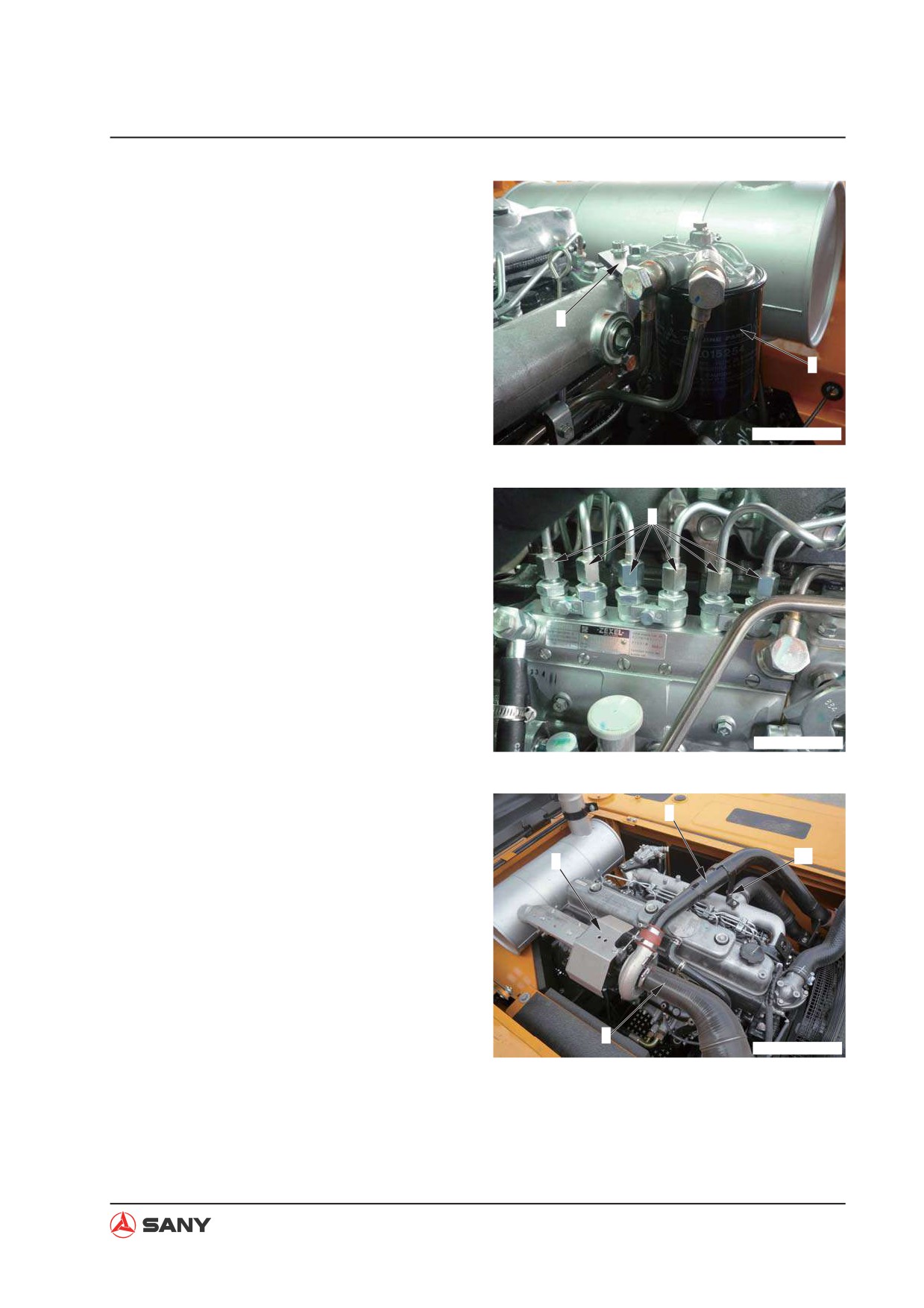
5. Remove the fuel filter bracket (4) and the
fuel filter assembly (5).
6. Remove the six delivery hoses (6).
4
5
ZX215T-1006019
7. Remove the exhaust muffler connector
cover (7).
6
ZX215T-1006020
8. Remove the air cleaner suction hose (8).
9
9. Remove the air intake tube (9) and its
clamps (10) between the turbocharger and
7
10
the intercooler.
10. Remove the engine oil delivery tube (11)
and the oil return tube (12).
8
ZX215T-1006021
8-19
Disassembly and Assembly
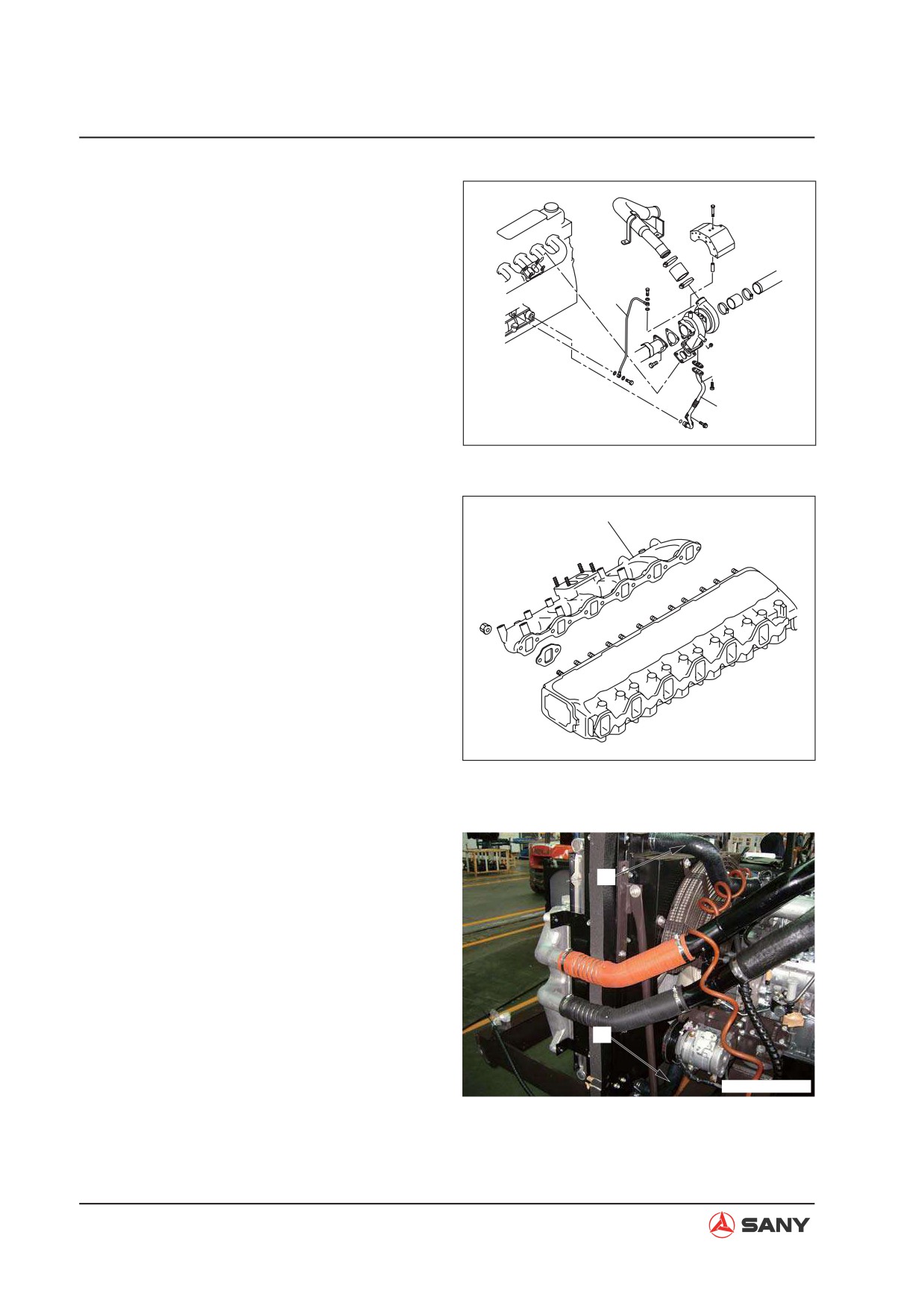
11. Remove the turbocharger assembly.
11
12
ZX215-1006022
12. Remove the exhaust manifold (13).
13
ZX215-1006023
13. Remove the radiator inlet hose (14) and
outlet hose (15).
14
15
ZX215T-1006024
8-20
Disassembly and Assembly
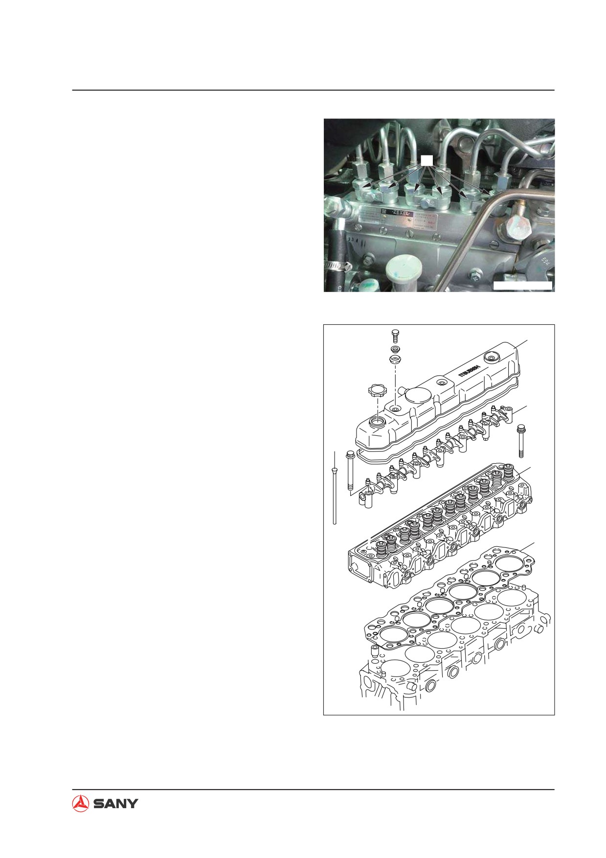
14. Remove the six nozzle seats (16).
16
ZX215T-1006025
15. Remove the rocker arm housing (17).
17
16. Remove the rocker arm assembly (18).
17. Remove the pushrod (19).
18. Remove the 25 mounting bolts from the
18
cylinder head assembly. Lift the cylinder
head assembly in order to disassemble it.
19
19. Remove the cylinder head gasket (21).
20
21
ZX215-1006026
8-21
Disassembly and Assembly
8.7.2 Installation
Ɣ The installation is to be performed in the
reverse order of removal.
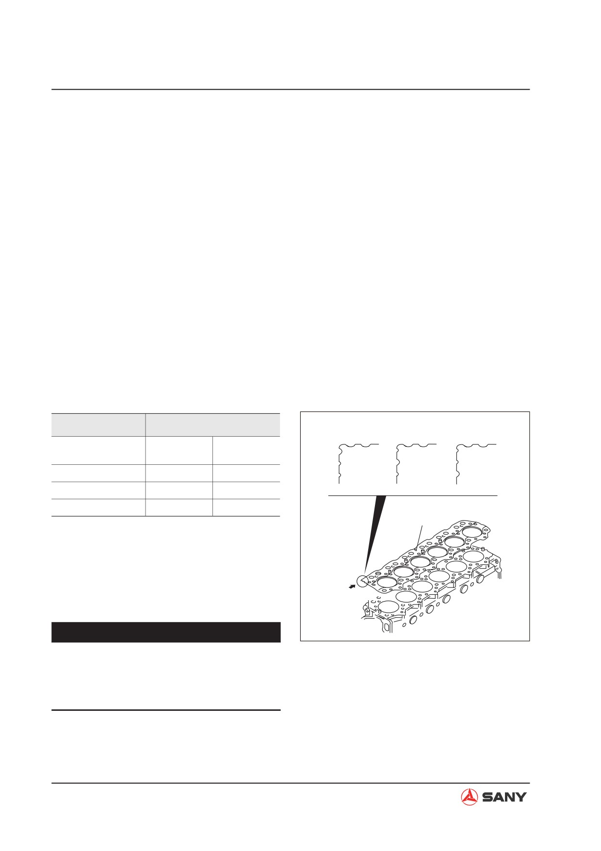
Installation of cylinder head gasket
Choose a cylinder head gasket as per the
following.
1. Measure the amount of piston projection of
each cylinder.
2. Select from the following table a gasket
with a thickness suitable for the maximum
piston projection after measurement. In ad-
dition, even if one cylinder's piston projec-
tion is 0.05 mm greater than the average,
the gasket with a thickness one grader
higher (AĺB, BĺC) is to be used.
Unit: mm
Piston Projection
Cylinder Head Gasket
Size mark
A
B
C
Thickness
Average
Size
Tightened
0.546~0.610
A
1.3
0.610~0.674
B
1.35
0.674~0.738
C
1.4
oUPp
3. The size of cylinder head gasket is deter-
mined according the notch.
4. Install the cylinder head gasket to the
crankshaft case as indicated by the arrow.
Notch
NOTICE
ZX215-1006027
The amount of piston projection must be
measured as the amount of piston projec-
tion may vary when replacing a piston or
connecting rod.
8-22
Disassembly and Assembly
Bolt (rocker cover installation):
4.9~6.9 N·m {0.5~0.7 kgf·m}
Bolt (cylinder head):
147 N·m {15 kgf·m}+90°
Bolt threads (cylinder head):
Engine oil
Tappet circumference:
Engine oil
Tappet ends:
Engine oil
Ɣ
Adjustment of valve clearance
For more information, see
“Valve
Clearance - Adjust” on page 6-8.
Ɣ
Adding coolant
Add engine coolant to the specified level.
Start the engine to circulate the coolant in
order to release all foams. Check the cool-
ant level again.
8-23
Disassembly and Assembly
8.8 Radiator AS - Remove and Install
8.8.1 Removal
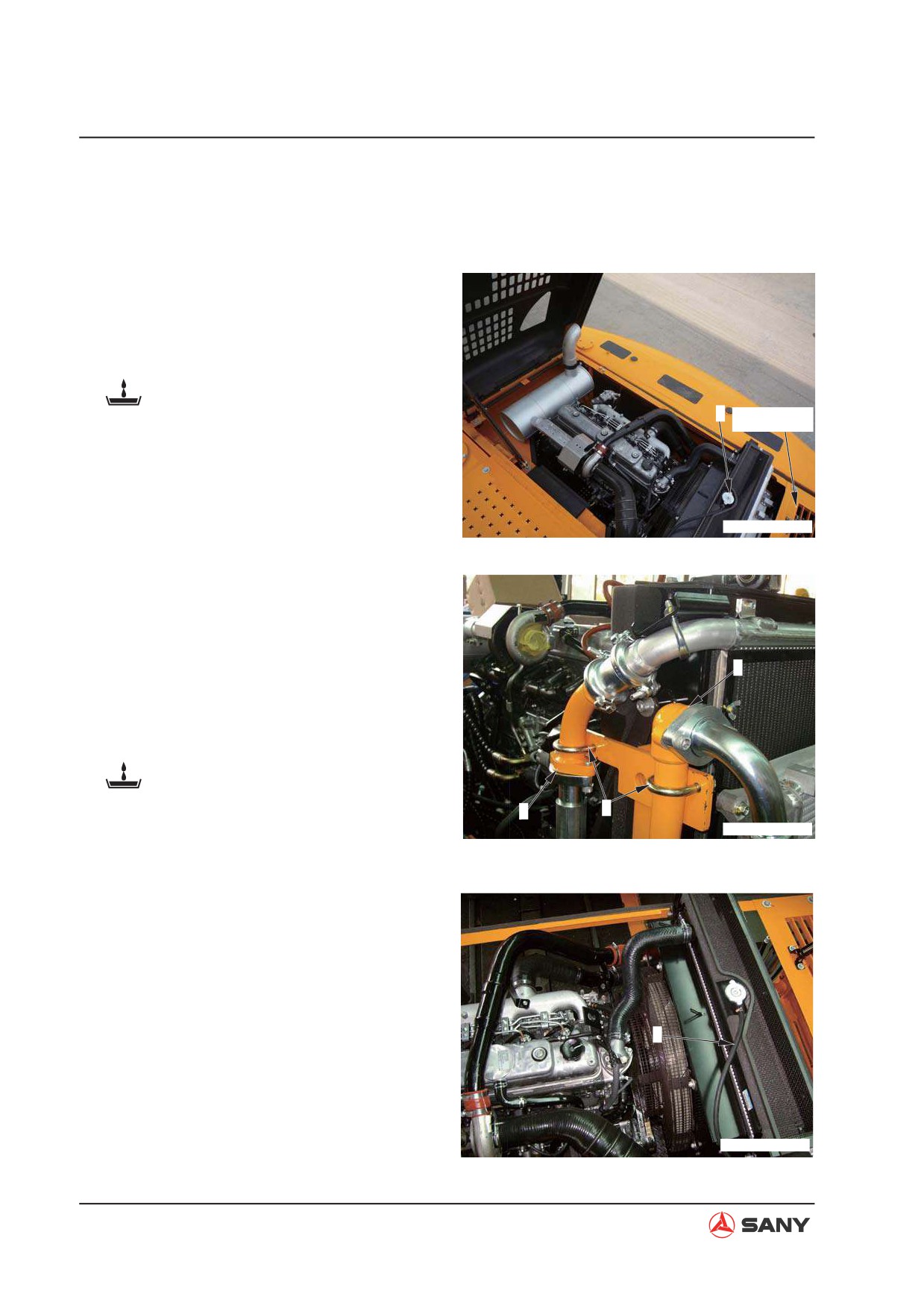
1. Open the engine hood.
2. Open the pressure cap (1). Open the drain
valve to discharge engine coolant from the
coolant tank.
Coolant: approx. 18 L
1
Cover plate
3. Remove the coverplate.
ZX215T-1006028
4. Remove the two U-bolts (2).
5. Disconnect the hydraulic oil cooler inlet
connector (3) and outlet connector (4).
Block the openings to prevent leakage of
3
hydraulic oil.
6. Discharge hydraulic oil from the hydraulic
cooler.
Hydraulic oil radiator: approx. 5.6 L
7. Disconnect the coolant tank hose (5).
4
2
ZX215T-1006029
8. Disconnect the cooler inlet hose (6) and
outlet hose (7).
5
ZX215T-1006030
8-24
Disassembly and Assembly
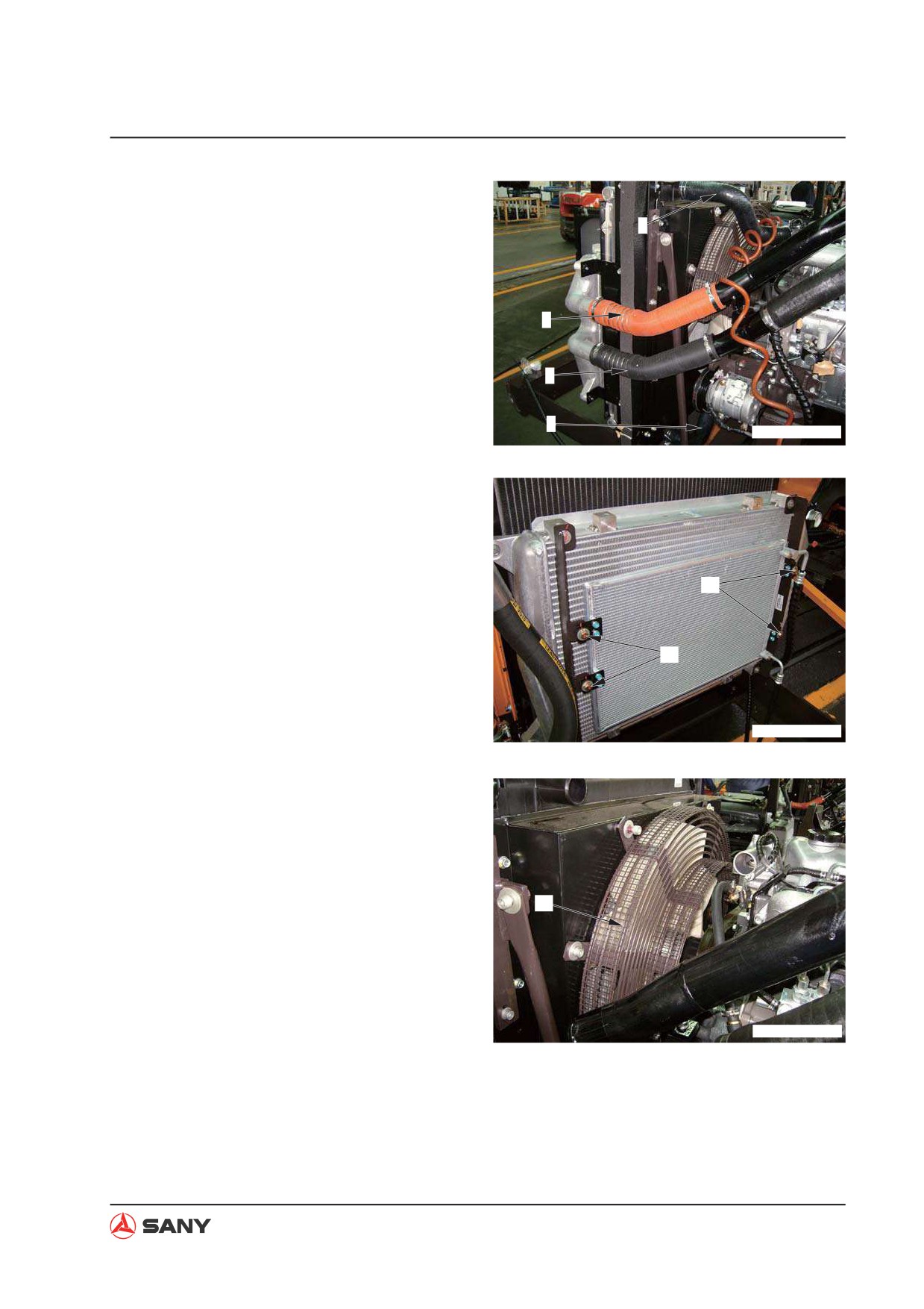
9. Disconnect the intercooler air inlet tube (8)
and outlet tube (9).
6
8
9
7
ZX215T-1006031
10. Remove the four bolts (10) from the air
conditioner radiator. Remove the air condi-
tioner radiator and store it properly.
10
10
ZX215T-1006032
11. Remove the radiator fan guard (11).
11
ZX215T-1006033
8-25
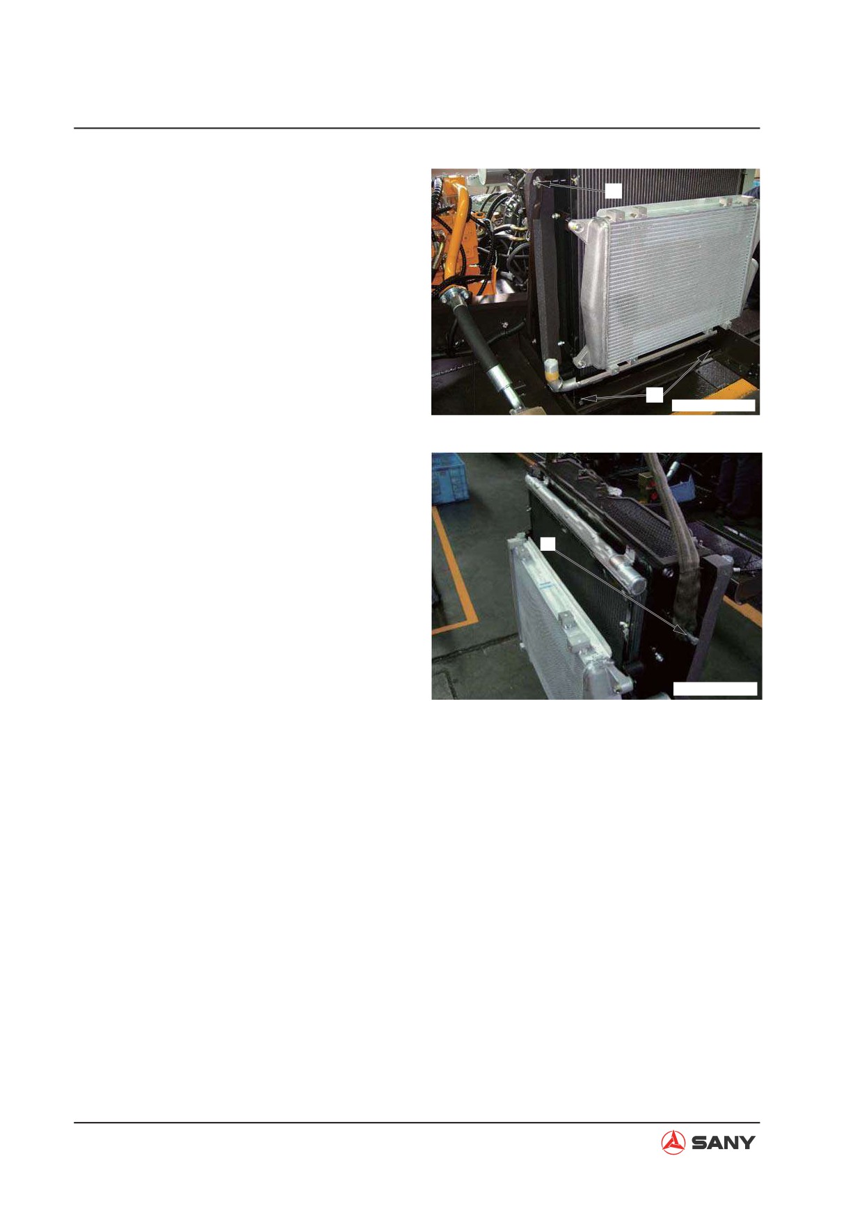
Disassembly and Assembly
12. Remove the four mounting bolts (12) from
13
the radiator bottom and the two mounting
bolts (13) from the left and right brackets.
12
ZX215T-1006034
13. Mount the hoisting bolts (14) to both sides
of the radiator in order to hoist the radiator
assembly.
NOTE: Before the radiator assembly is
14
hoisted, move the radiator assembly axially
until the fan avoids its guard.
ZXT335-1006029
8-26
Disassembly and Assembly
8.8.2 Installation
Ɣ Installation is to be performed in the re-
verse order of removal.
NOTE:
Ɣ Adjust the clearance (a) between the fan
and the fan guard in order to have a uni-
form clearance surrounding the fan.
Ɣ Check the values (a) at the four measuring
points in the left, right, top and bottom di-
rections, which should be as the following:
Standard clearance (a) in all directions:
15±1.5 mm
Fan diameter (b): ø620 mm
Fan guard inner diameter (c): ø650 mm
Ɣ Engine coolant and hydraulic oil adding
Add a specific amount of coolant and
hydraulic oil. Start the engine to circulate
the coolant and hydraulic oil. Check the
coolant level and the oil level.
Engine coolant: approx. 18 L
Hydraulic oil radiator: approx.
12 L
8-27
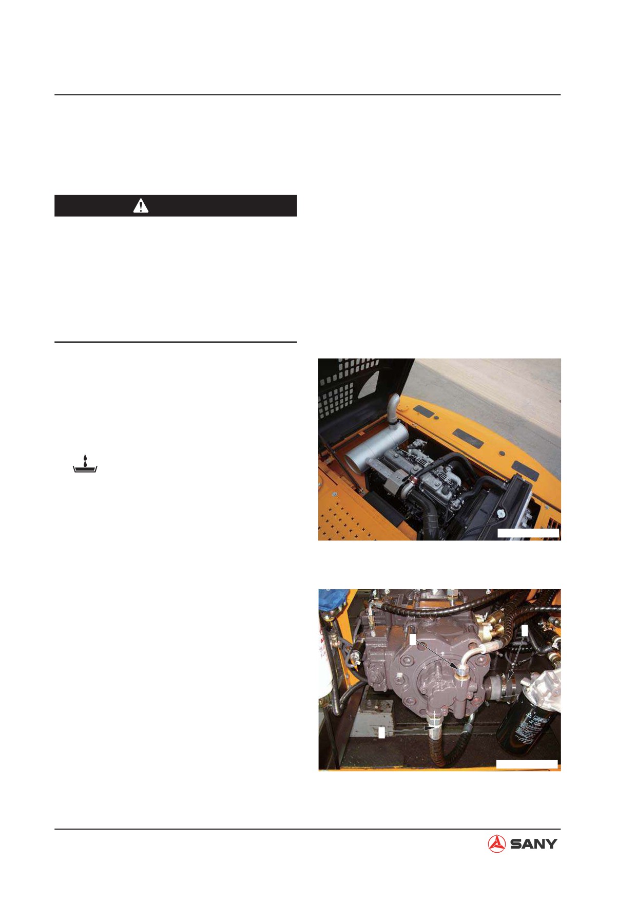
Disassembly and Assembly
8.9 Engine and Hydraulic Pump AS - Remove and Install
8.9.1 Removal
CAUTION
Ɣ Lower the work equipment to the
ground. Stop the engine. Disconnect
the cable from the battery negative (-)
post.
Ɣ Loosen the butterfly nut on the breather
valve and press the relief button to re-
lieve internal pressure.
NOTE: Mark the lines to avoid mistakes during
reinstallation.
1. Remove the hydraulic tank suction filter el-
ement and block the opening.
2. Drain the engine of coolant.
Coolant: approx. 18 L
3. Open the engine hood.
ZX215T-1006028
4. Disconnect piping (1), (2) and (3).
3
2
1
ZX215T-1006036
8-28
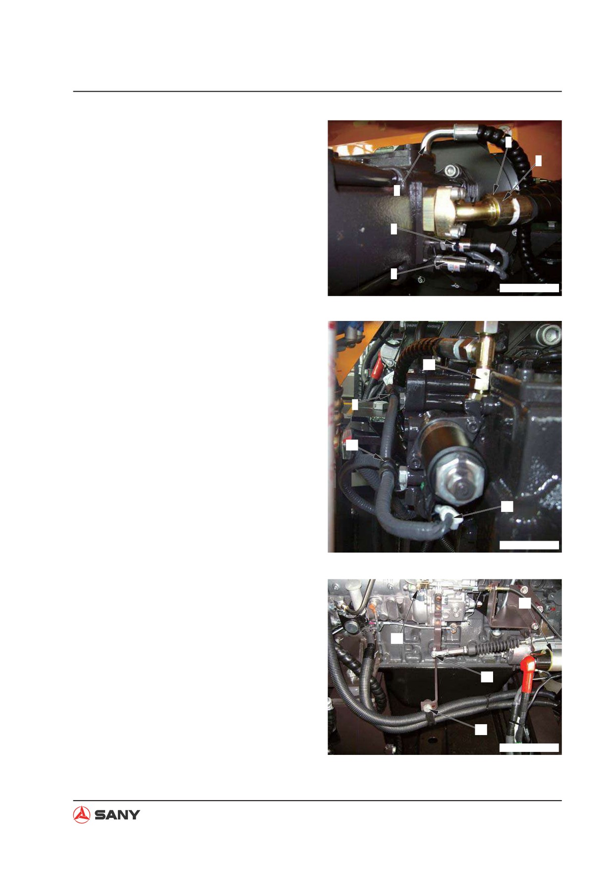
Disassembly and Assembly
5. Disconnect piping (4), (5) and (6).
5
6. Remove the sensors (7) and (8).
6
4
7
8
ZX215T-1006037
7. Remove the clamps (9) and (10). Remove
the line (11) and the cable (12).
11
9
10
12
ZX215T-1006038
8. Unscrew the connection bolt (13) of the
governor motor and the connection bolt (14)
15
of the engine stopper.
9. Disconnect the external cable from the
14
starter (15).
10. Remove the mounting bolt (16) from the
13
hose clamp.
16
ZX215T-1006039
8-29