SANY Crawler Hydraulic Excavator (SY195C9, SY205C9, SY215C9, SY225C9). Shop Manual (2013) - page 15
Structure and Function
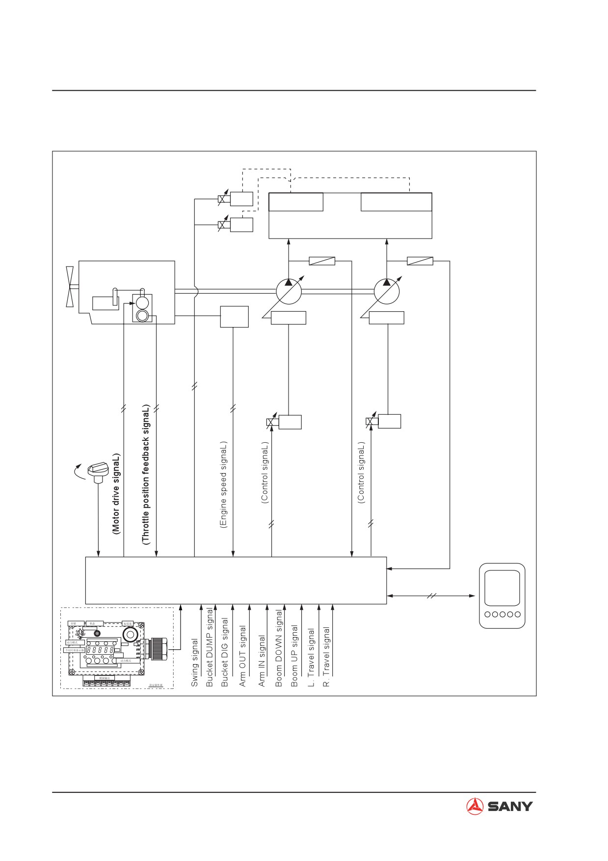
4.9.10 Engine speed calibration function
Swing pripority
Bucket confluence
Main valve
Pressure sensor
Pressure sensor
Engine
Main pump
Injection
Throttle
pump
motor
F
R
M
Speed
P
Servo
Servo
sensor
Fuel control dial
Hi
Lo
Monitor
Controller
(CAN bus)
Calibtator
SW
LED
MEMORYON
LED
H
S
L
A/I
DOWN
UP
7
RPW
LED
SW
H
S
L
A/I
ZX215-1002207
4-190
Structure and Function
Function
Ɣ Set the maximum engine speed under
each working mode. This set speed is the
standard to control engine speed.
Operation
Ɣ Calibrating procedure for positive flow exca-
vators.
1) Selection of fixing point of throttle motor
soft shaft
2) H, S, L maximum speed calibration, and A/
I speed calibration.
3) Turn the dial on the calibrator counter-
clockwise to the end
4) Power OFF
5) Set the calibrator to "Monitor mode", power
on and check the result.
Remark:
Memory SW up: Calibration mode;
Memory SW down: Monitor mode
For more information, see “Engine Speed -
Test and Calibrate” on page 6-3.
4-191
Structure and Function
4.9.11 Electrical Components
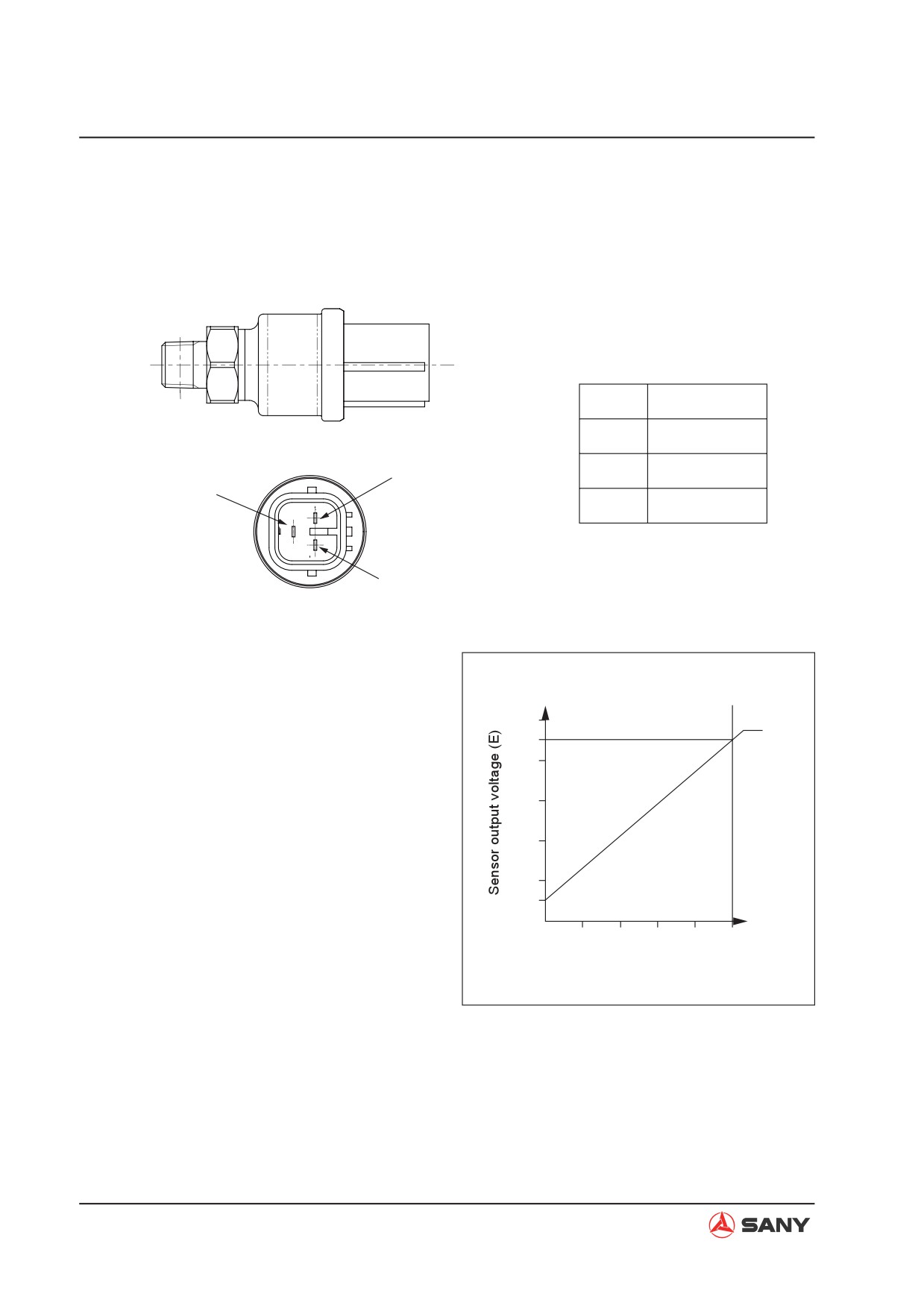
4.9.11.1 Pump pressure sensor
Connection diagram
No.
Signal name
A
PWR +5V
B
Output
Terminal C
Terminal B
C
Terminal A
ZX305-1002066
Operation
Ɣ The relationship between the pressure ap-
(V)
plied on the sensor (P) and output voltage
(E) is shown in the right diagram.
(MPa)
Oil pressure (P)
ZX215-1002209
4-192
Structure and Function
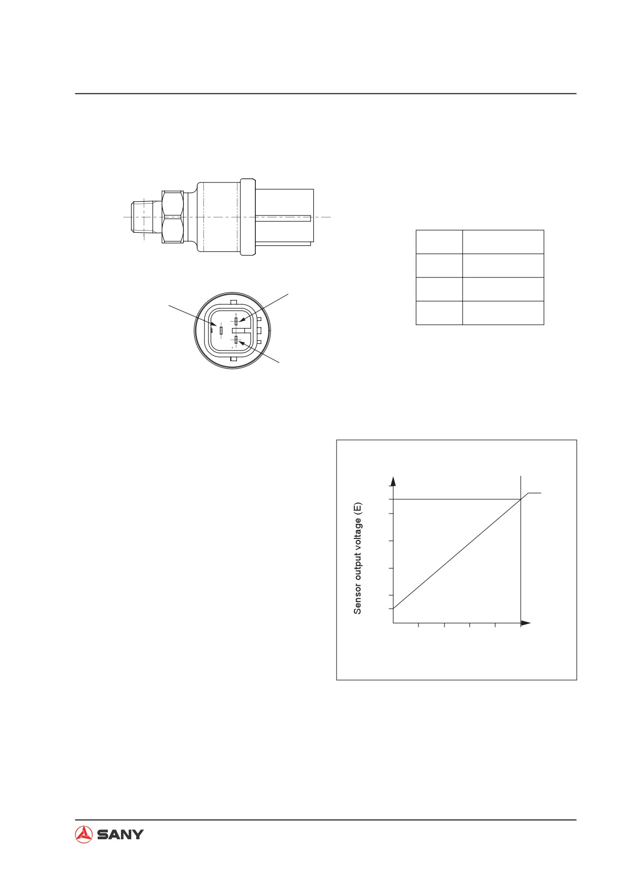
4.9.11.2 Pilot pressure sensor
Connection diagram
No.
Signal name
A
PWR +5V
Terminal C
B
Output
Terminal B
C
Terminal A
ZX305-1002066
Operation
Ɣ The relationship between the pressure ap-
plied on the sensor (P) and output voltage
(E) is shown in the right diagram.
(V)
(MPa)
Oil pressure (P)
ZX215-1002210
4-193
Structure and Function
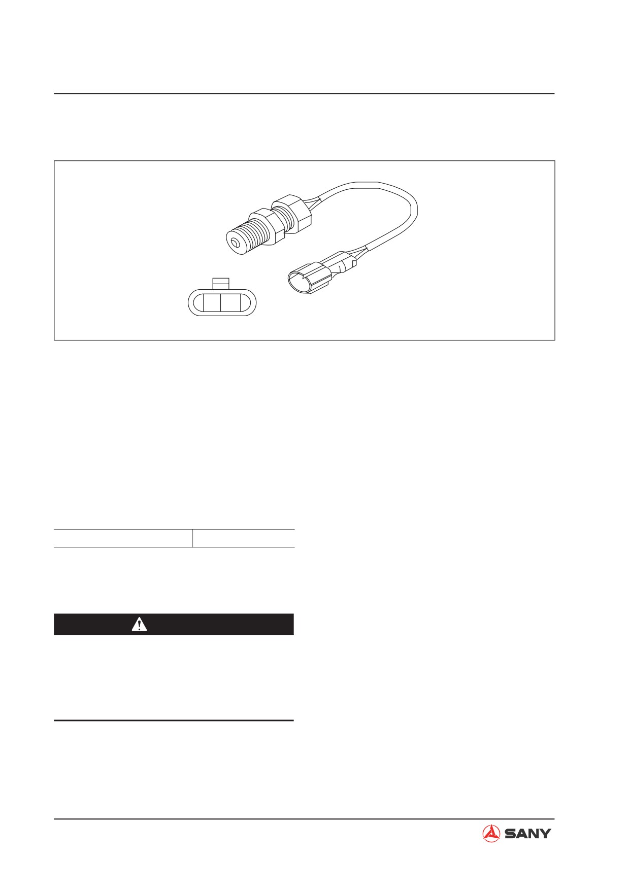
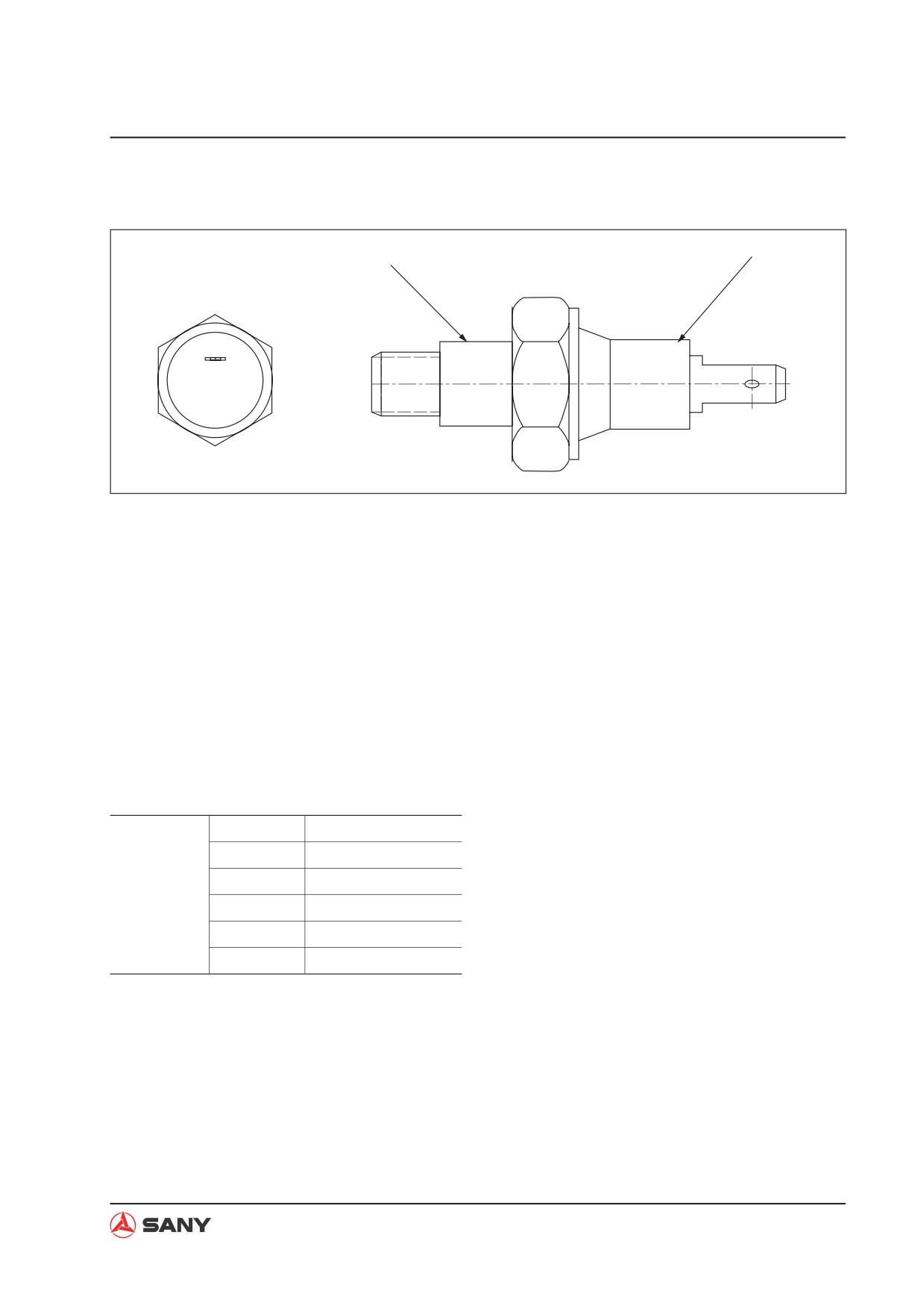
4.9.11.3 Engine speed sensor
2
1
ZX215-1002211
Function
Ɣ The engine revolution sensor is installed to
the ring gear of the engine flywheel. It elec-
trically calculates the number of the gear
teeth which pass in front of it and transmits
the result to the engine controller.
Operation
Ɣ Measure the resistance between terminal
1 and terminal 2 when it is in service.
Standard value (@25°C)
2.3±0.2 kȍ
Ɣ If the measured value exceeds the stan-
dard value, replace the sensor.
CAUTION
Ɣ If the engine speed sensor is not tight-
ened to the specified torque, the sensor
may send out no signals. Tighten the
engine speed sensor to the specified
torque.
4-194
Structure and Function
4.9.11.4 Coolant temperature sensor
2
1
ZX215-1002212
1) Sensor
2) Connector
Function
Ɣ The output resistance of the engine cool-
ant temperature sensor changes with the
coolant temperature. The controller collects
and processes coolant temperature signals
and works out the coolant temperature.
Specifications
50°C
80ȍ (Ref.)
60°C
56.3ȍ
Standard
80°C
29.5±10ȍ
value
100°C
16.5ȍ
106°C
14.3±0.5ȍ
120°C
10ȍ(Ref.)
4-195
Structure and Function
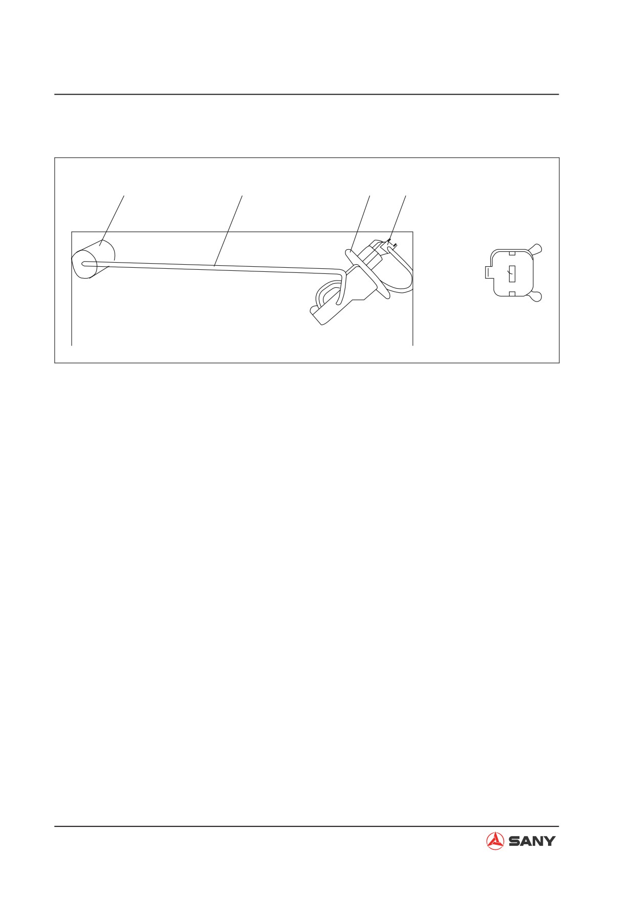
4.9.11.5 Fuel level sensor
1
2
3
4
ZX215-1002246
1) Float
3) Casing
2) Lever
4) Coupler
4-196
Structure and Function
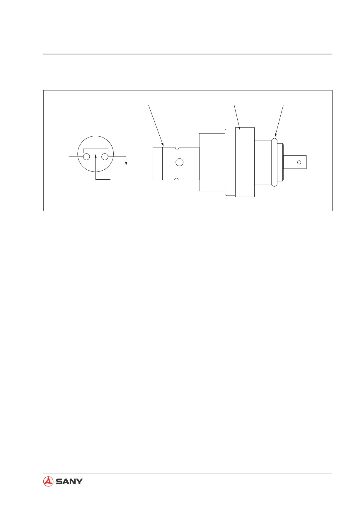
4.9.11.6 Oil pressure switch
1
2
3
Load
Pressure
ZX215-1002214
1) O-ring
2) Sensor
3) Connector
Function
Ɣ The oil pressure switch is installed on the
outlet circuit of the oil filter. It detects oil
pressure and transmits warning signals to
the controller.
Specifications
Ɣ Type of contact: Normally closed type
Ɣ Operating pressure: 1.9kg
4-197
Structure and Function
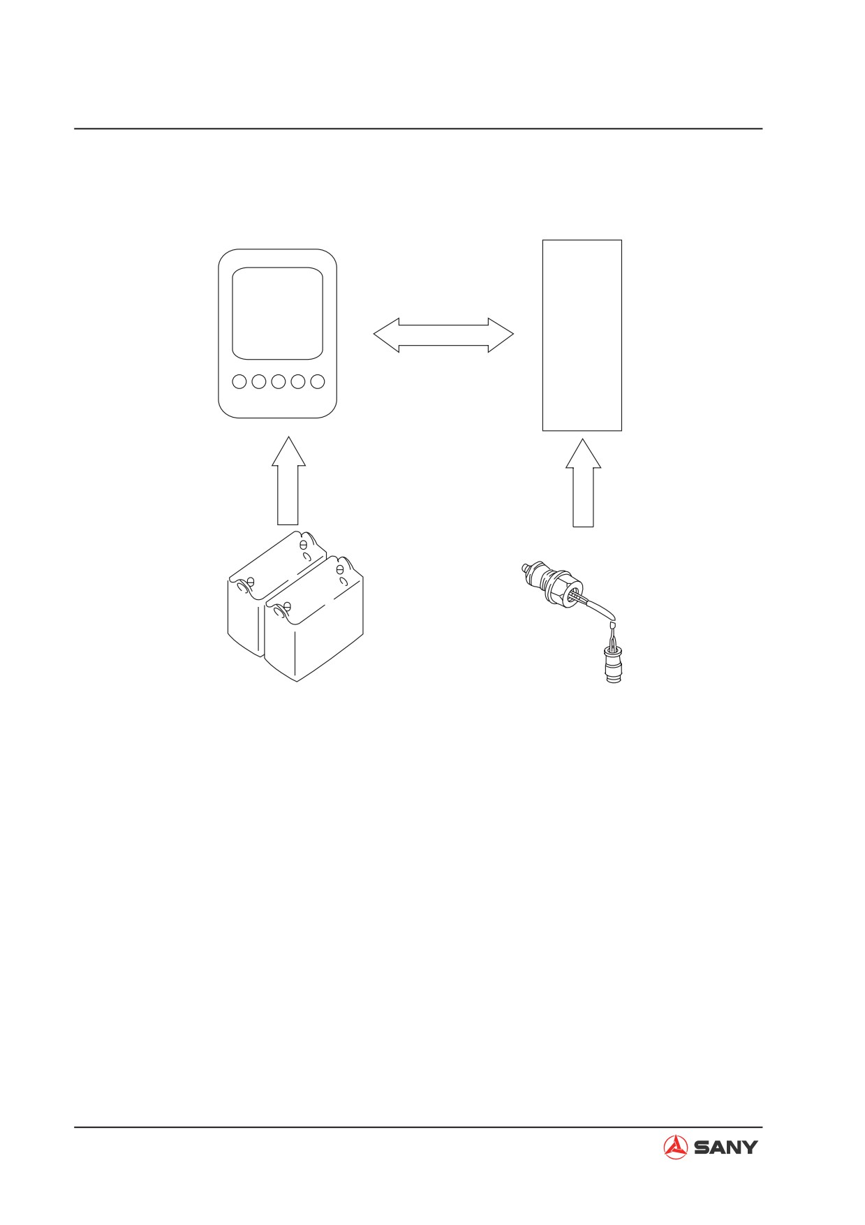
4.10 Monitoring System
CAN signal
Monitor
Controller
Power
Sensor
Battery
W13053001
Ɣ The state of the machine is monitored
1. Alert information when a machine fault is
by the sensors mounted on the machine
detected.
components. The controller processes the
2. Operating condition (coolant temperature,
signals and transmits the signals to the
fuel level, etc. )
monitor display, informing the operator of
the machine condition.
Ɣ The machine control system can be oper-
ated using the switches and keys on the
Ɣ Information on the monitor display includes
monitor panel.
primarily:
4-198
Structure and Function
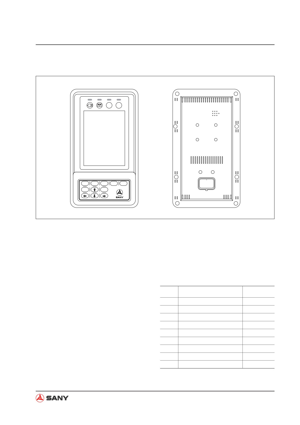
4.10.1 Machine monitor
$
%
F1
F2
F3
F4
F5
Esc
Enter
WX215-1204002H
Outline
Ɣ The monitor displays various kinds of items
Ɣ When the monitor is turned on, blinking
and is used by the operator to select a
strips may appear on the LCD screen.
working mode.
This is normal.
Ɣ The monitor has a CPU which processes,
displays, and outputs information.
Input and output signals
Ɣ The monitor has an LCD (Liquid Crystal
Display) screen.
No.
Signal name
Input/output
NOTE:
1
Digital input A
Input
3
CAN high
Ɣ The LCD may have black spots (which do
4
CAN low
not light up) or bright spots (which stay on).
7
Digital input B
Products having 10 or less black or bright
8
Trigger power source (24V)
spots conform to the product specification;
such condition is quite normal.
9
Power source (24V)
10
Grounding
Ɣ Continuous operation of the monitor may
11
Digital input C
cause the LCD to display bright blue spots
12
Grounding
on a black background; it is quite normal.
4-199
Structure and Function
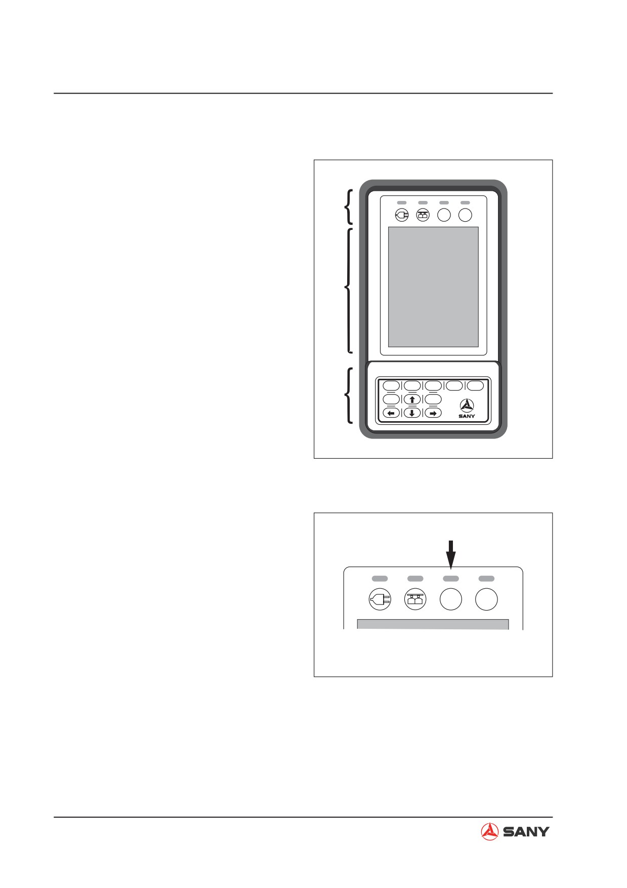
4.10.2 Monitor functions
The front side of the machine monitor is made
up of three sections:
A. Warning and signal indicators
A
$
%
B. Display screen
C. Key pad
B
F1
F2
F3
F4
F5
C
Esc
Enter
XP13031506
Warning and signal indicators
Ɣ When a machine fault occurs, the warning
indicator lights up, reminding the user to
check and address the fault.
$
%
XP13031505
4-200
Structure and Function
Screen display
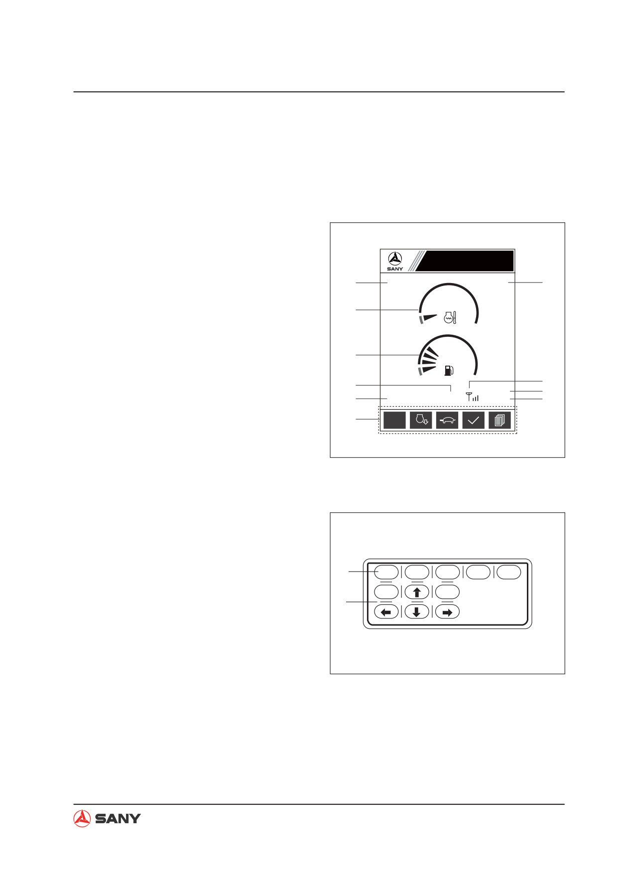
The LCD display is where monitor items are
shown. This display is also the interface where
most monitor operations are performed. Items
on a normal operation display include:
1. Working mode indicator
2. Coolant temperature gage
Sany Hydraulic Excavator
3. Fuel level gage
1
6
10
4. Failure code
5. Total service hours
2
C
H
6. Function icons
7. System time (Hr: Min: Sec)
3
8. Date (YY:MM:DD)
E
F
9
4
9. GPS signal
8
5
K
P
(
7
10. Engine speed level (1 to 11)
6
AUTO
6
n/min
XP13032601
Key pad
The key pad is composed of 5 function keys
and six navigation keys.
1
F1
F2
F3
F4
F5
Esc
Enter
2
XP13031502
4-201
Structure and Function
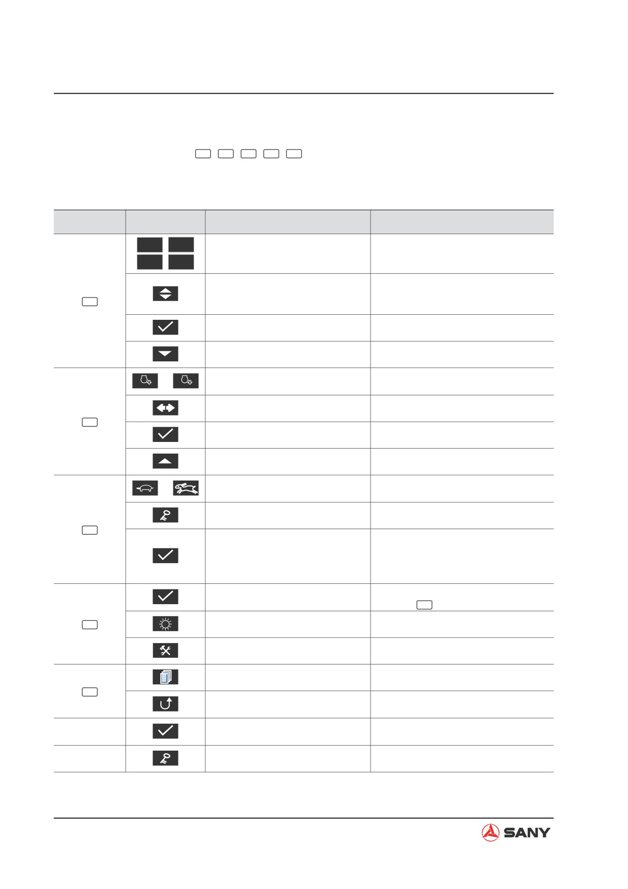
1. Function keys
Functions of the five keys (
F1
,
F2
,
F3
,
F4
,
F5
) are indicated by the function icons above them
on the screen.
Function keys and icons
Function key
Icon
Function
Operation interface
S
,
H
Working mode selection
Home page
L
,
B
Select the next item;
Information Menu page
Go to the next page;
Engine and Throttle Signal page, etc.
F1
Increase password value
Password Entry page
Save
System Time Calibration page, etc.
Lower monitor brightness
Brightness Adjustment page
AUTO
Switch between Auto idle and Non
n/min
or
n/min
Home page
auto idle
Move the cursor to the right
Password Entry page
F2
Enter a selected entry
Information Menu page, etc.
Increase monitor brightness
Brightness Adjustment page
Switch between High and Low
or
Home page
travel speed
Password validation
Password Entry page
F3
Confirm the validity of a password
Password Entry page
and, if it’s correct, enter the de-
sired page.
Save monitor brightness
Brightness Adjustment page
Go to “Fault Information” page
Home page
Enter/Confirm
Same as
Enter
F4
Go to Brightness Adjustment page
Password Entry page
Go to System Setup page
Information Menu page
Go to Information Menu
Home page
F5
Return to Home page, Information
Password Entry page, etc.
Menu or System Setup page
Machine Configuration Calibration
Save
page
Go to System Unlock page
Lockout Information page
NOTE: When no icon is displayed above a function key, this key is disabled.
4-202
Structure and Function
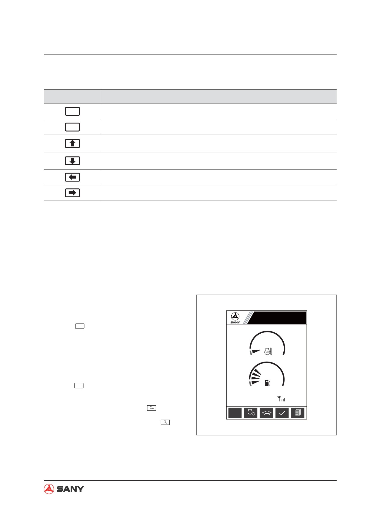
2. Navigation keys
Navigation keys
Function
Enter
Enter/Confirm
ESC
Return
Select the item above (returns to the bottom item after the top item); or increase the
value where the cursor blinks.
Select the item below (returns to the top item after the bottom item); or decrease the
value where the cursor blinks.
Move the cursor to the left (returns to the right end digit after the left end digit).
Move the cursor to the right (returns to the left end digit after the right end digit).
4.10.3 Monitor operation
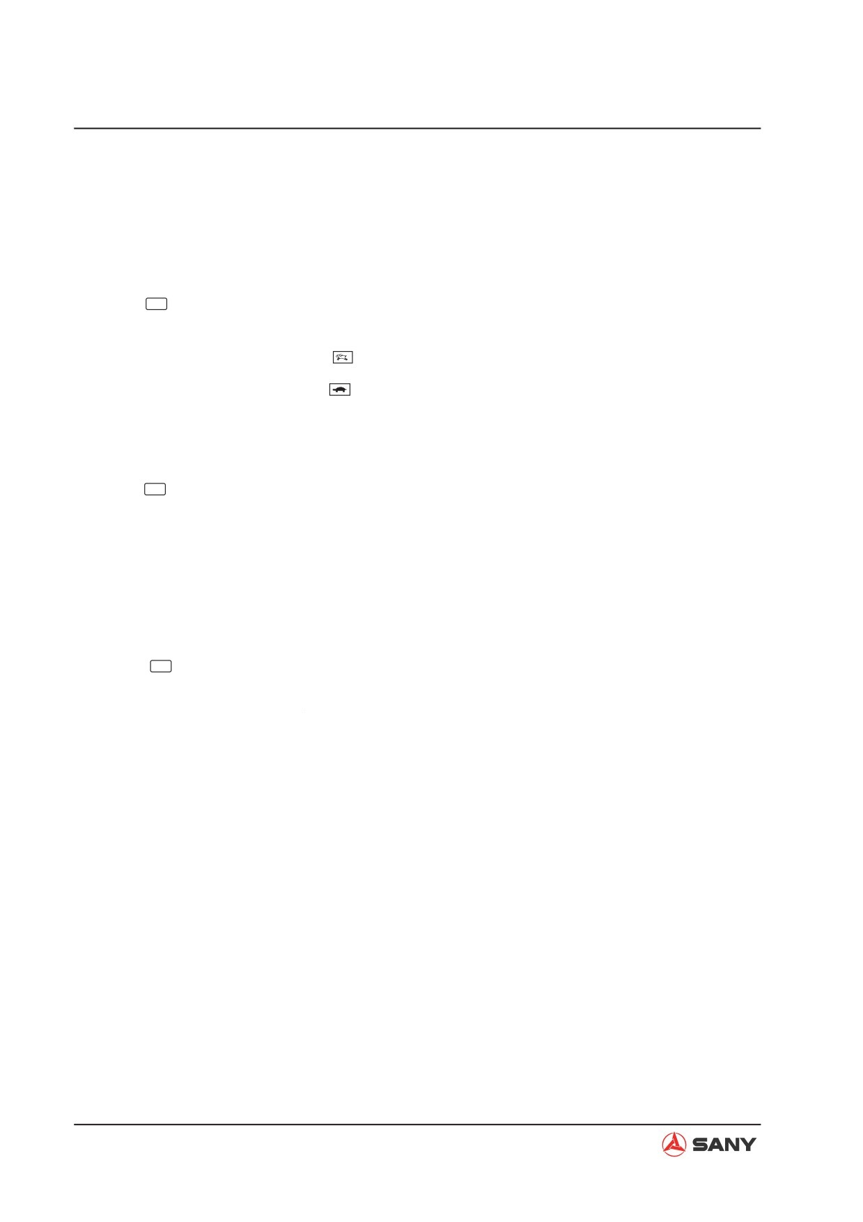
1. Home page
The Home page is the normal operation display of the monitor. Items on this page include:
truck load counter, working mode, speed level, coolant temperature, fuel level, service hours,
clock, fault code, etc..
Operation
Working mode selection (1)
Sany Hydraulic Excavator
Ɣ Press
F1
switch between S, H. L and B
6
mode.
NOTE: S mode is the default working
C
H
mode.
Auto-idle and Non auto-idle mode (2)
Ɣ Press
F2
to switch between auto-idle and
E
F
Non auto-idle mode.
K P
(
AUTO
Auto-idle mode is indicated by
n/min
AUTO
6
n/min
Non auto-idle mode is indicated by
n/min
XP13032602
NOTE: Auto-idle mode is the default mode.
4-203
Structure and Function
When neither of the joysticks are operated
for 5 seconds, the engine enters the idling
state automatically in order to save fuel
and reduce noise.
High and low travel speed (3)
Ɣ Press
F3
to switch between high and low
travel speed.
High travel speed is indicated by
Low travel speed is indicated by
NOTE: Default travel speed is Low.
Fault Information (4)
Ɣ Press
F4 to go to “Fault Information” when
a fault occurs.
NOTE: When the ECU detects an error in
the machine, a fault code will appear on
the monitor display. The tick icon on the
bottom will turn red.
Information Menu (5)
Ɣ Press
F5
to go to the Password Entry
page before accessing the “Information
Menu” page.
4-204
Structure and Function
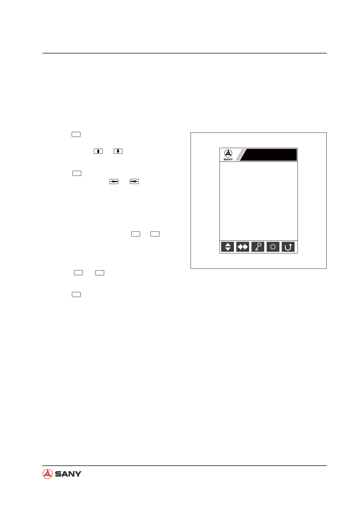
2. Information Menu password entry
A 5-digit password is required to access the
“Information Menu”. You can ask your local
dealer to obtain this password.
Operation
1. Press
F1
to change the number where the
cursor blinks in an ascending order. You
can also use
or
to increase or de-
Information Menu
crease the number.
2. Press
F2
to move the cursor to the right.
You can also use
or
to move the
Please enter the password
cursor to the left or to the right.
̷Ḥ̷Ḥ̷Ḥ̷Ḥ̷
NOTE: The cursor moves back to the left
end side after the right end side.
3. When all the five digits of the password
have been entered, press
F3
or
Enter
. If the
password is correct, the display moves to
the “Information Menu” page; if not, please
try again.
XP13031501
4. Press
F5
or
ESC
to return to the Home
page.
5. Press
F4
on this page to go to Brightness
Adjustment page.
4-205
Structure and Function
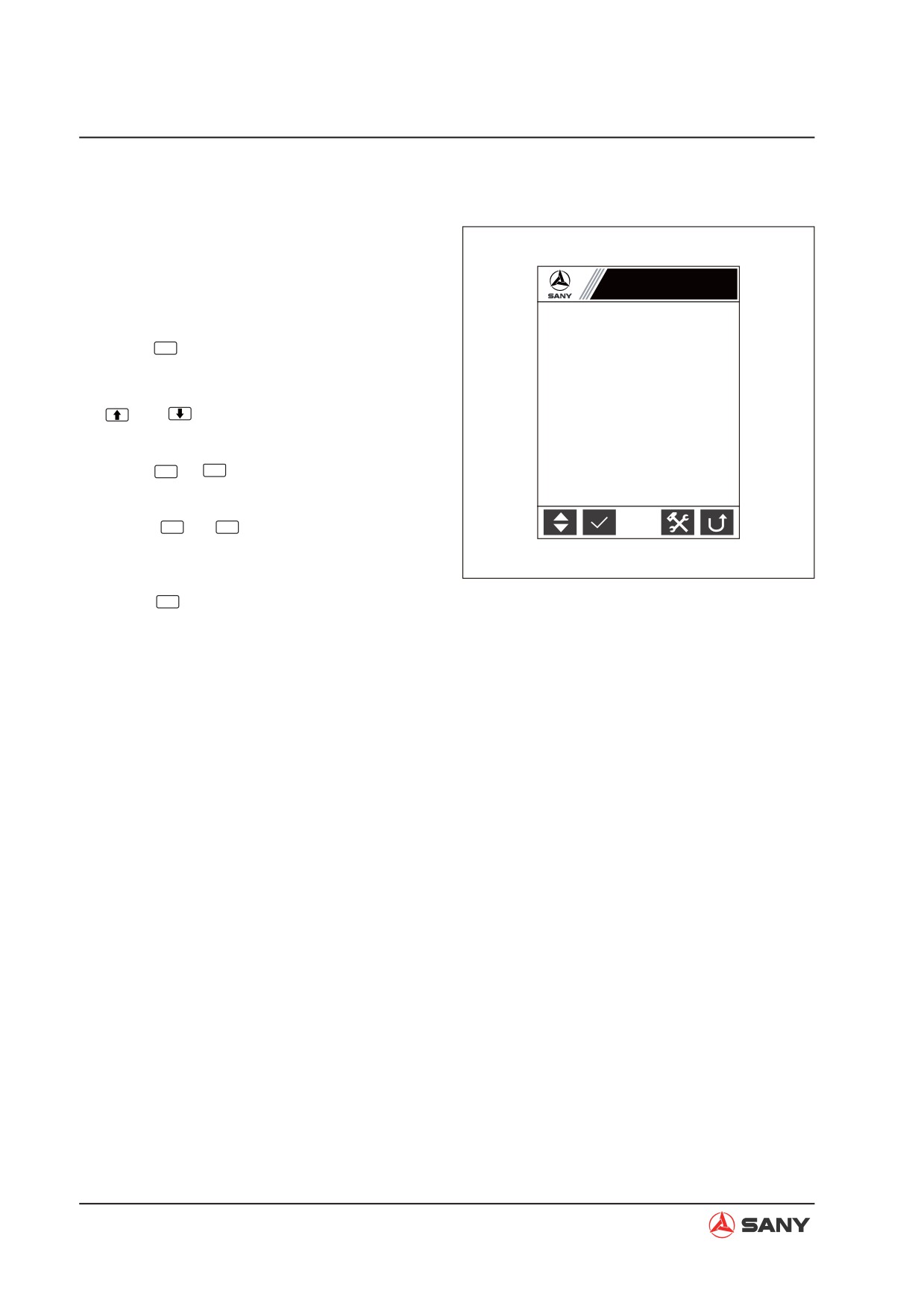
3. Information Menu
The information menu is a list of system func-
tions. On this page, you can select and access
any of the items on the list.
Information Menu
Operation
Running parameter
Ɣ Press
F1
to select the item below the high-
Fault information
lighted one. The highlighter returns to the
Throttle installation
top after the bottom item. You can also use
System language
and
to move the highlighter up and
System time setup
down.
GPS monitoring
Ɣ Press
F2
or
Enter
to access the selected en-
try.
Engine, pump and valve parameters
Ɣ Press
F5
or
ESC
to return to the Home
page.
XP1251203007
Ɣ Press
F4
on this page to go to the Pass-
word Entry page before accessing the Sys-
tem Setup page.
NOTE: Once an entry on the list is highlighted,
an introductory hint will appear on the bottom
of the display giving a short description of the
selected entry. These hints include:
Ɣ Running parameters of the engine, main
pup and main valve
Ɣ Fault code and description
Ɣ Throttle installation assistance
Ɣ System language selection
Ɣ System time setup
Ɣ GPS monitoring information
4-206
Structure and Function
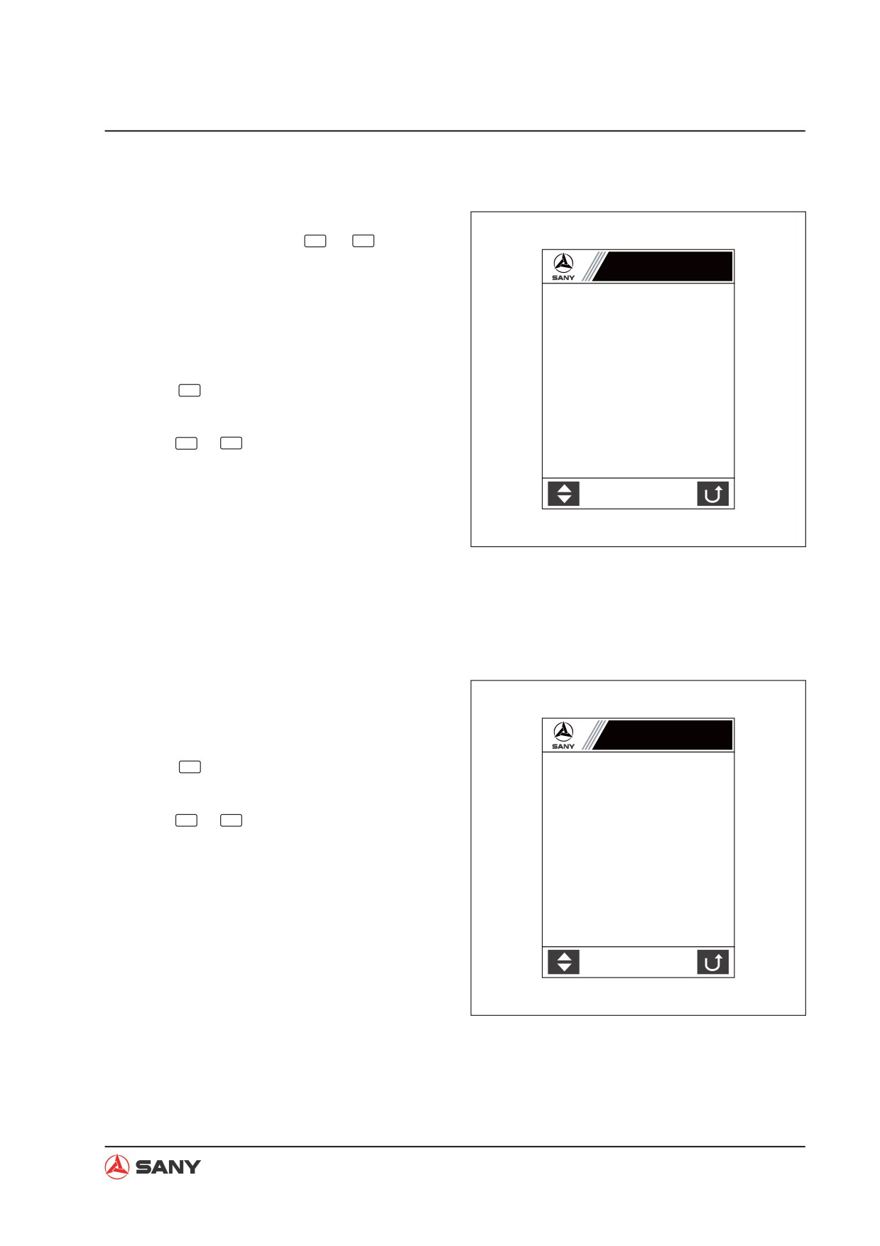
4. Engine & Throttle Signal
Select “Running Parameter” on the Informa-
tion Menu page and press
F2
or
Enter
, and the
display moves to Engine & Throttle Signal
Engine & Throttle Signal
page. This page is a real-time display of the
running parameter of the engine and throttle.
Coolant temp °C:
Fuel level %:
Oil press kPa:
Operation
Throttle gear:
Ɣ Press
F1
to go to “Pilot Pressure Signal”
Eng speed rpm:
page.
Gear position V:
Ɣ Press
F5
or
ESC
to return to the “Information
Throt position V:
Menu”.
XP1251203008
5. Pilot Pressure Signal
This page is a real-time display of the pilot
pressure signal of the hydraulic system.
Operation
Pilot Pressure Signal
Ɣ Press
F1
to go to “Main Pump and Main
Boom UP kg:
Valve Signal” page.
Boom DOWN kg:
Arm IN kg:
Ɣ Press
F5
or
ESC
to return to the “Information
Arm OUT kg:
Menu”.
Bucket DIG kg:
Bucket DUMP kg:
Swing kg:
Travel L kg:
Travel R kg:
XP2051203009
4-207
Structure and Function
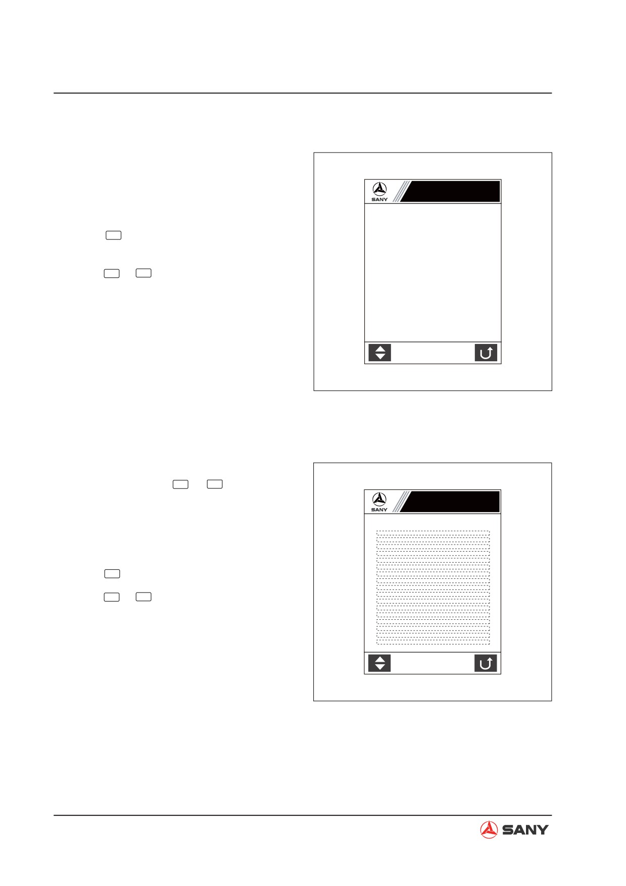
6. Main Pump & Main Valve Signal
This page is a real-time display of the main
pump and main valve signals of the hydraulic
system.
Main Pump & Main Valve Signal
Operation
Pump1 press kg
Ɣ Press
F1
to go to “Engine & Throttle Sig-
Pump2 press kg
nal” page.
Prop valve1 current mA
Prop valve2 current mA
Ɣ Press
F5
or
ESC
to return to the “Information
Bucket confluence valve ż
Menu”.
Swing priority valve ż
Boom priority valve ż
Hi/Lo speed switch ż
XP2051203010
7. Fault Information
Select “Fault Information” on the Information
Menu page and press
F2
or
Enter
, and the dis-
play moves to Fault Information page. This
Fault Information
page lists important machine fault information.
Current fault code:XXX
XXX:
XXX:
XXX:
Operation
XXX:
XXX:
XXX:
Ɣ Press
F1
to go to the next page.
XXX:
XXX:
XXX:
XXX:
Ɣ Press
F5
or
ESC
to return to the “Information
XXX:
XXX:
Menu”.
XXX:
XXX:
XXX:
XXX:
XXX:
XP13041501
4-208
Structure and Function
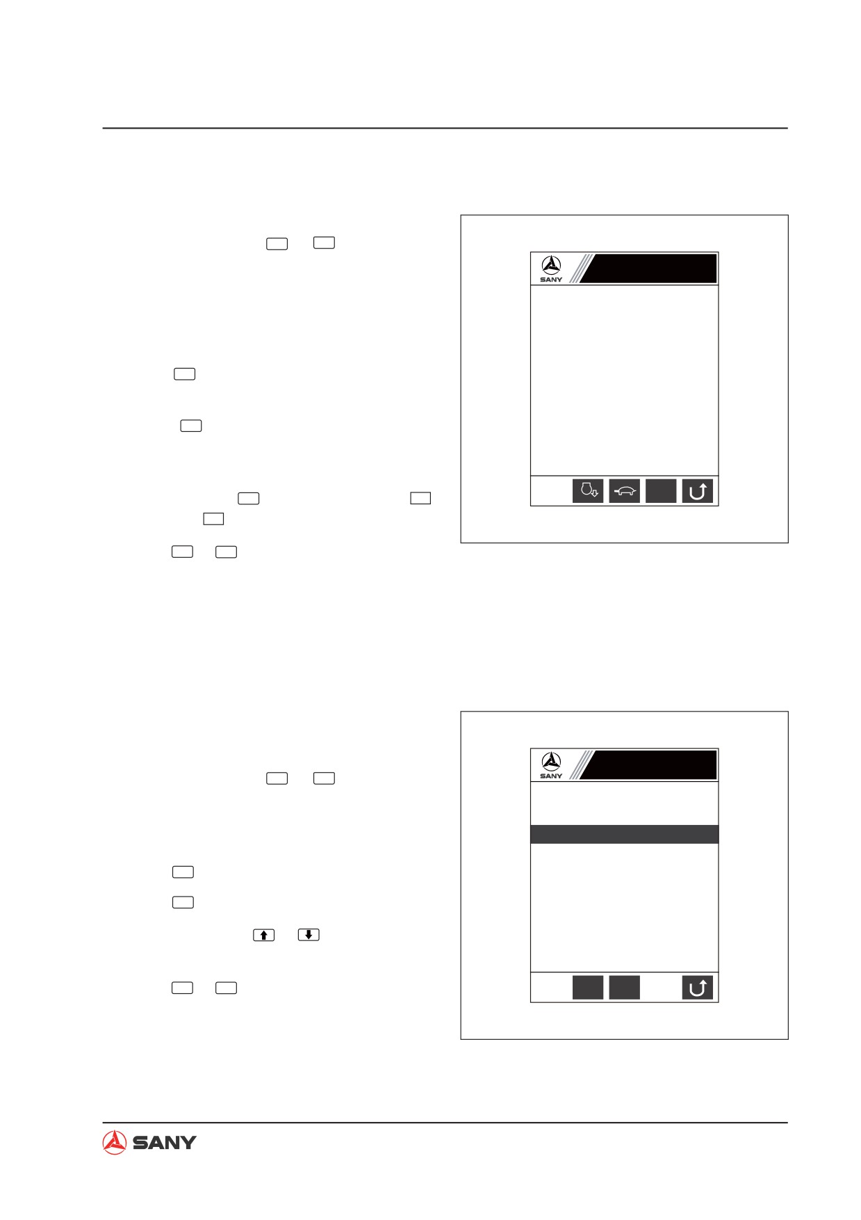
8. Throttle Installation
Select “Throttle Installation” on the Information
Menu page and press
F2
or
Enter
, and the dis-
play moves to Throttle Installation page. This
Throttle Installation
page displays throttle installation assistance
function.
Current gear N
Operation
Eng speed rpm
1200 ?
Ɣ Press
F2
to switch between auto-idle and
Gear position V
full speed.
Throttle position V
Ɣ Press
F3
to select high or low travel
speed.
Ɣ For machines equipped with SYFCS con-
AUTO
rpm
rpm
n/min
trollers, press
F4
to switch between
(blue) and
rpm
(red).
XP2051203013
Ɣ Press
F5
or
ESC
to return to the “Information
Menu”.
NOTE: For machines equipped with SYFCS
controllers, when engine speed calibration is
not successful, a question mark will appear.
9. System Language
Select “System Language” on the Information
System Language
Menu page and press
F2
or
Enter
, and the dis-
play moves to this page.
Ё᭛㋏㒳
Operation
English Systems
Ɣ Press
F2 to select ᇏ໓.
Ɣ Press
F3
to select English.
Ɣ You can also use
or
to select a sys-
tem language on the list.
Ɣ Press
F5
or
ESC
to return to the “Information
Ё᭛
(QJ
Menu”.
XP2051203014
4-209