SANY Crawler Hydraulic Excavator (SY195C9, SY205C9, SY215C9, SY225C9). Shop Manual (2013) - page 2
Introduction
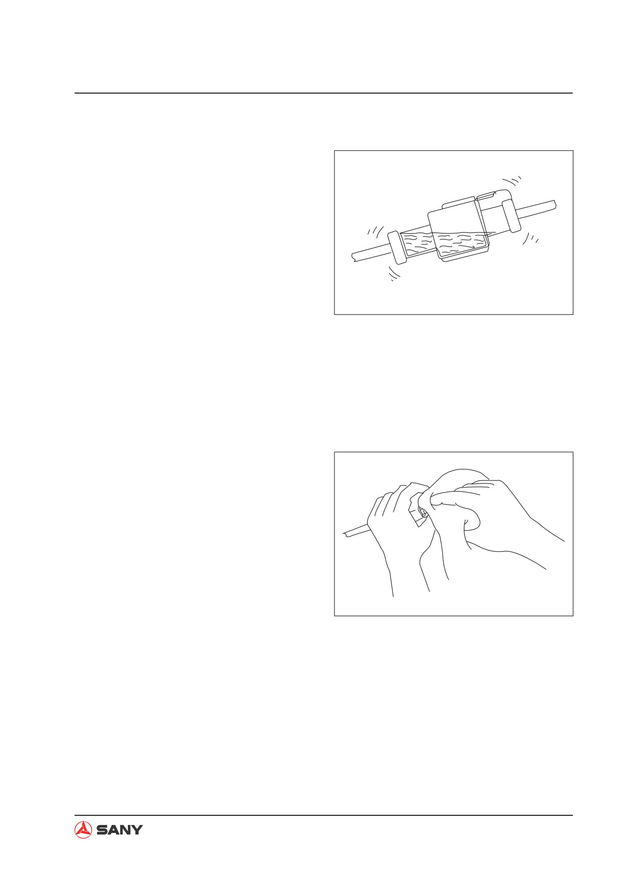
4) High-pressure water entering connector
The connector is designed to make it
difficult for water to enter
(drip-proof
structure), but if high-pressure water is
sprayed directly on the connector, water
may enter the connector, depending on the
direction of the water jet. Accordingly, take
care not splash water over the connector.
The connector is designed to prevent
water from entering, but at the same time,
if water does enter, it is difficult for it to
be drained. Therefore, if water should get
ZX215-1000008
into the connector, the pins will be short-
circuited by the water, so if any water gets
in, immediately dry the connector or take
other appropriate action before passing
electricity through it.
5) Oil or dirt stuck to connector
If oil or grease are stuck to the connector
and an oil film is formed on the mating
surface between the male and female pins,
the oil will not let the electricity pass, so
there will be defective contact. If there is
oil or grease stuck to the connector, wipe
it off with a dry cloth or blow it dry with
compressed air and spray it with a contact
restorer.
NOTE:
ZX215-1000009
Ɣ When wiping the mating portion of the
connector, be careful not to use exces-
sive force or deform the pins.
Ɣ If there is oil or water in the com-
pressed air, the contacts will become
even dirtier, so remove the oil and wa-
ter from the compressed air completely
before cleaning with compressed air.
1-9
Introduction
3. Removing, installing, and drying con-
nectors and wiring harnesses
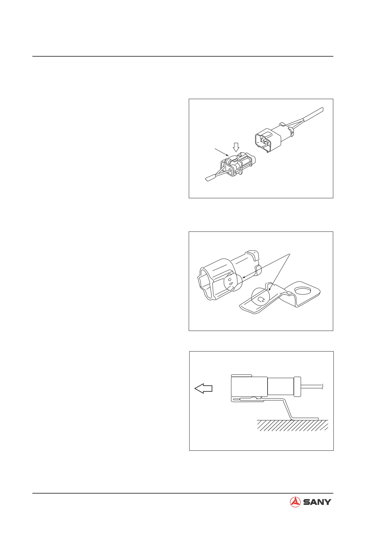
1) Disconnecting connectors
a. Hold the connectors when disconnect-
ing.
Press lightly
when removing
When disconnecting the connectors,
Lock stopper
hold the connectors. For connectors
held by a screw, loosen the screw fully,
then hold the male and female connec-
tors in each hand and pull apart. For
connectors which have a lock stop-
per, press down the stopper with your
ZX215-1000010
thumb and pull the connectors apart.
NOTE: Never pull with one hand.
b. When removing from clips
Ɣ Both of the connector and clip have
Both stoppers
stoppers, which are engaged with each
other when the connector is installed.
ZX215-1000011
Ɣ When removing a connector from a clip,
pull the connector in a parallel direction
to the clip for removing stoppers.
ZX215-1000012
1-10
Introduction
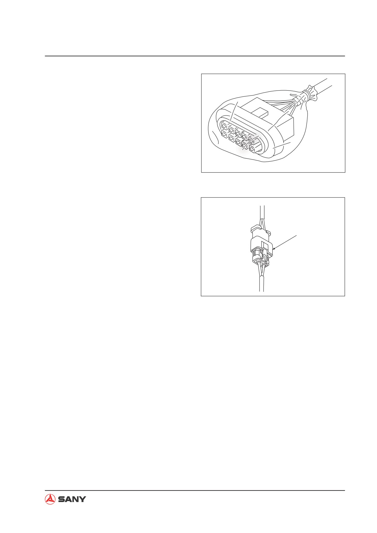
c. Action to take after removing connec-
tors
After removing any connector, cover
it with a vinyl bag to prevent any dust,
dirt, oil, or water from getting in the
connector portion.
NOTE: If the machine is left disas-
sembled for a long time, it is particularly
easy for improper contact to occur, so
always cover the connector.
ZX215-1000013
2) Connecting connectors
a. Check the connector visually
Check that there is no oil, dirt, or water
Clicks into position
stuck to the connector pins (mating por-
tion).
Check that there is no deformation, de-
fective contact, corrosion, or damage to
the connector pins.
ZX215-1000022
Check that there is no damage or
breakage to the outside of the connec-
tor.
NOTE: If there is any oil, water, or dirt
stuck to the connector, wipe it off with
a dry cloth. If any water has got inside
the connector, warm the inside of the
wiring with a dryer, but be careful not to
make it too hot as this will cause short
circuits.
NOTE: If there is any damage or break-
age, replace the connector.
1-11
Introduction
b. Fix the connector securely.
Align the position of the connector cor-
rectly, and then insert it securely. For
connectors with lock stopper, push in
the connector until the stopper clicks
into position.
c. Correct any protrusion of the boot and
any misalignment of the wiring harness.
For connectors fitted with boots, correct
ZX215-1000014
any protrusion of the boot. In addition, if
the wiring harness is misaligned, or the
clamp is out of position, adjust it to its
correct position.
NOTE: If the connector cannot be cor-
rected easily, remove the clamp and
adjust the position.
Ɣ If the connector clamp has been re-
moved, be sure to return it to its origi-
nal position. Check also that there are
no loose clamps.
ZX215-1000015
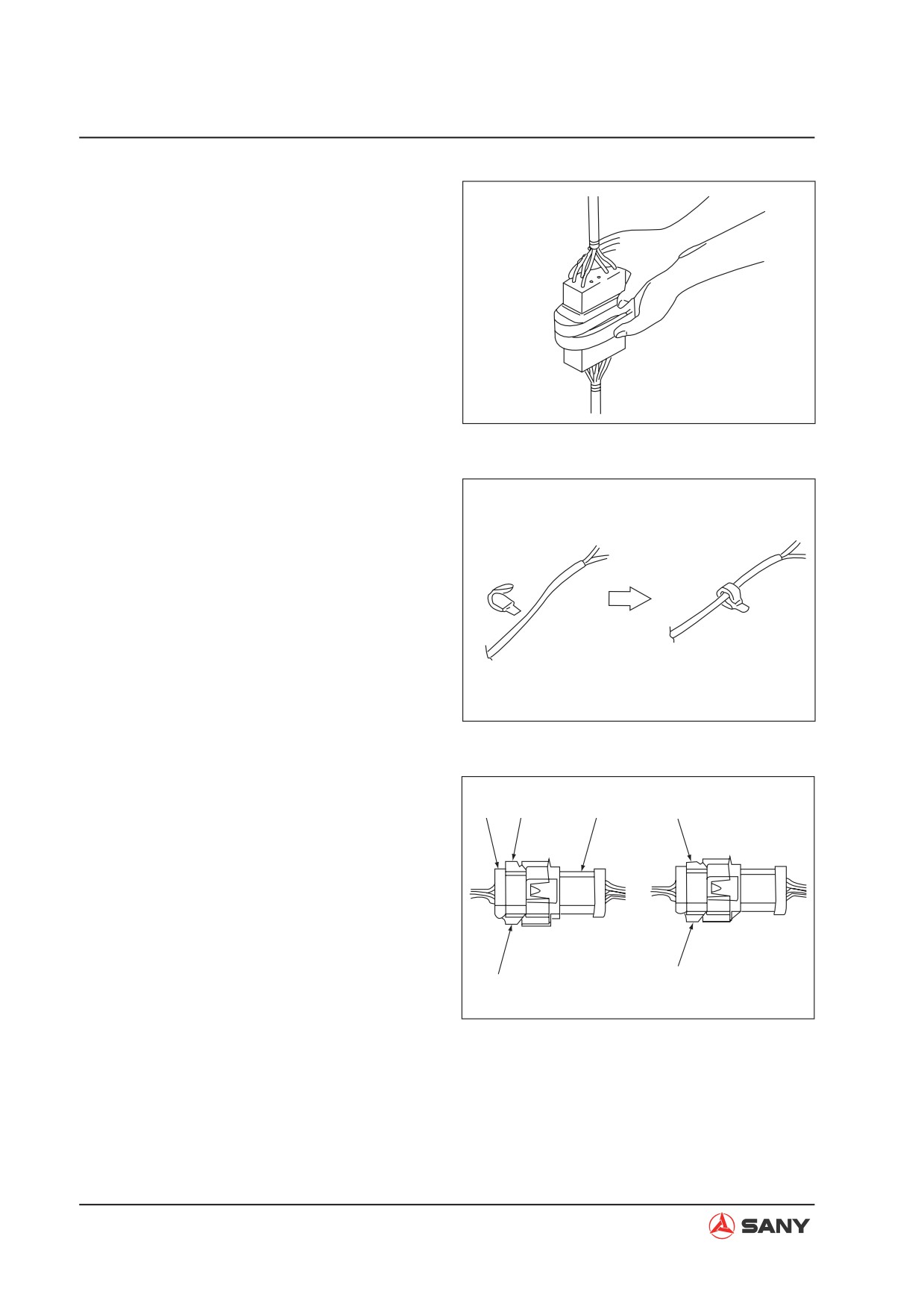
3) Connecting DT connectors
2
a
1
c
Since the DT 8-pin and 12-pin heavy duty
wire connectors have 2 latches respec-
tively, push them in until they click 2 times.
Ɣ Male connector: 1
Ɣ Female connector: 2
Ɣ Normal locking state (Horizontal): a, b,
d
b
d
ZX215-1000016
Ɣ Incomplete locking state (Diagonal): c
1-12
Introduction
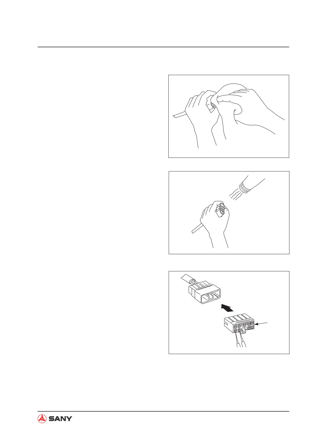
4) Drying wiring harness
If there is any oil or dirt on the wiring
harness, wipe it off with a dry cloth. Avoid
washing it in water or using steam. If the
connector must be washed in water, do not
use high-pressure water or steam directly
on the wiring harness. If water gets directly
on the connector, do as follows.
a.
Disconnect the connector and wipe off
the water with a dry cloth.
NOTE: If the connector is blown dry
ZX215-1000009
with compressed air, there is the risk
that oil in the air may cause defective
contact, so remove all oil and water
from the compressed air before blowing
with air.
b.
Dry the connector with a dryer.
If water gets inside the connector, use
a dryer to dry the connector.
NOTE: Hot air from the dryer can be
used, but regulate the time that the
hot air is used in order not to make the
ZX215-1000017
connector or related parts too hot, as
this will cause deformation or damage
to the connector.
c.
Carry out a continuity test on the con-
nector.
After drying, leave the wiring harness
disconnected and carry out a continuity
test to check for any short circuits be-
T adapter
tween pins caused by water.
NOTE: After completely drying the con-
nector, blow it with contact restorer and
ZX215-1000018
reassemble.
1-13
Introduction
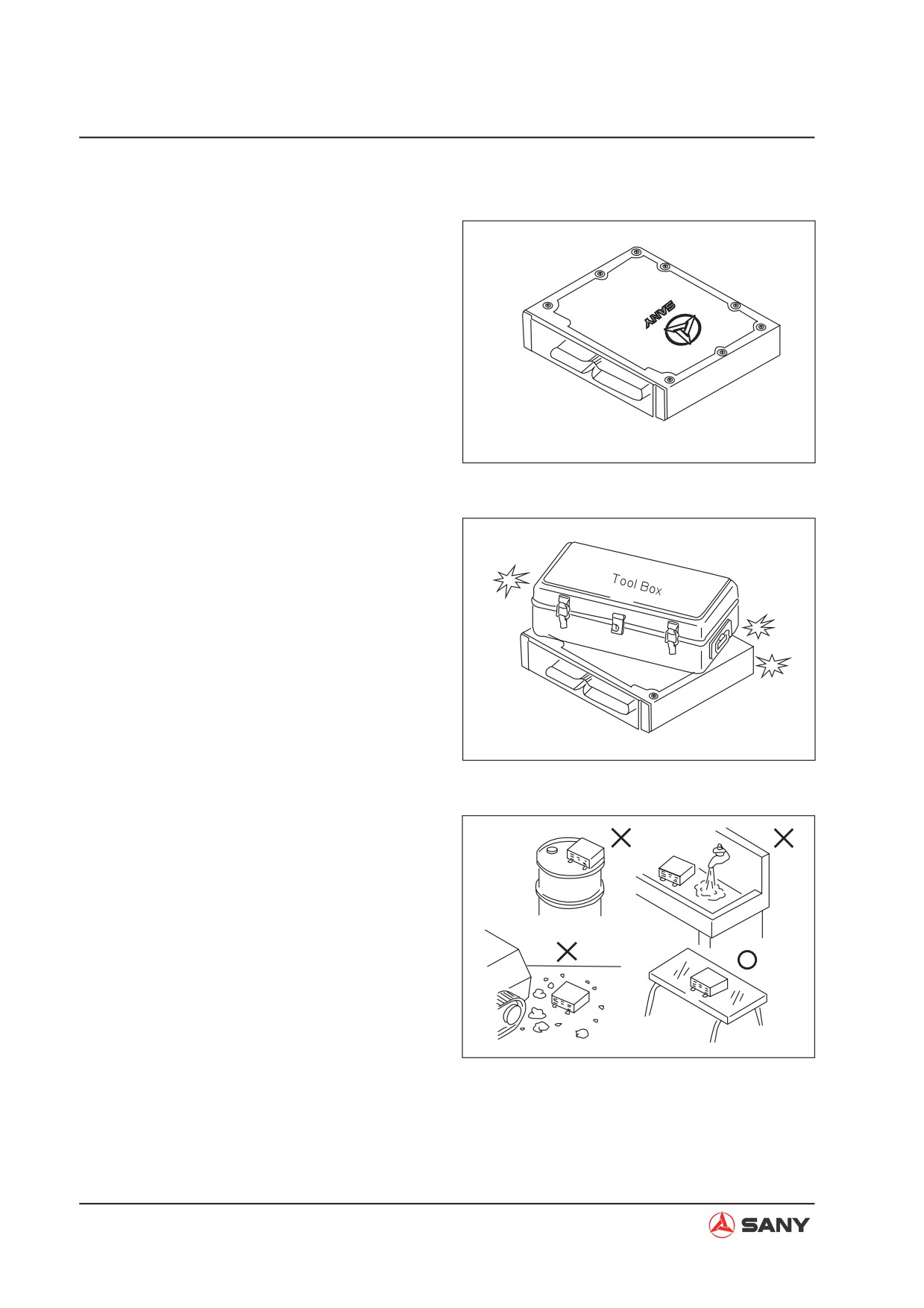
4. Handling the integrated control monitor
1) The controller contains a microcomputer
and an electronic control circuits. They
control all of the electronic circuits on the
machine, so be extremely careful when
handling the integrated control monitor.
2) Do not place objects on the controller.
3) Cover the control connectors with tape or a
ZX215-1000019
vinyl bag. Never touch the connector con-
tacts with your hand.
4) Do not leave it where it may be exposed to
rain.
5) Do not place the controller on oil, water, or
soil, or in any hot place, even for a short
time.
6) Precautions for arc welding
When welding on the controller, disconnect
all wiring harness connectors connected
to the controller. Fit an arc welding ground
ZX215-1000020
close to the welding point.
ZX215-1000021
1-14
Introduction
5.
Points to remember when troubleshoot-
ing electric circuits
1) Always turn the power OFF before discon-
necting or connecting connectors.
2) Before carrying out troubleshooting, check
that all the related connectors are properly
inserted.
NOTE: Disconnect and connect the related
connectors several times to check.
3) Always connect any disconnected connec-
tors before going on to the next step.
NOTE: If the power is turned ON with the
connectors still disconnected, unnecessary
abnormality displays will be generated.
4) When carrying out troubleshooting of cir-
cuits (measuring the voltage, resistance,
continuity, or current), move the related
wiring and connectors several times and
check that there is no change in the read-
ing of the tester.
NOTE: If there is any change, there is
probably defective contact in that circuit.
1-15
Introduction
1.3.2 Points to remember when handling hydraulic equipment
With the increase in pressure and precision
of hydraulic equipment, the most common
cause of failure is dirt (foreign material) in the
hydraulic circuit. When adding hydraulic oil, or
when disassembling or assembling hydraulic
equipment, it is necessary to be particularly
careful.
1. Be careful of the operating environment
Avoid adding hydraulic oil, replacing filters,
or repairing the machine in rain or high
winds, or places where there is a lot of
dust.
2. Disassembly and maintenance work in
the field
If disassembly or maintenance work is
carried out on hydraulic equipment in the
field, there is danger of dust entering the
equipment. It is also difficult to check the
performance after repairs, so it is desir-
able to use unit exchange. Disassembly
and maintenance of hydraulic equipment
should be carried out in a specially pre-
pared dust-proof workshop, and the perfor-
mance should be checked with special test
equipment.
3. Sealing openings
After any piping or equipment is removed,
the openings should be sealed with caps,
tapes, or vinyl bags to prevent any dirt or
dust from entering. If the opening is left
open or is blocked with a rag, there is
danger of dirt entering or of the surround-
ing area being made dirty by leaking oil so
never do this. Do not simply drain oil out
onto the ground, but collect it and ask the
customer to dispose of it, or take it back
with you for disposal.
Introduction
4.
Do not let any dirt or dust get in during
refilling operations
Be careful not to let any dirt or dust get
in when refilling with hydraulic oil. Always
keep the oil filler and the area around it
clean, and also use clean pumps and oil
containers. If an oil cleaning device is
used, it is possible to filter out the dirt that
has collected during storage, so this is an
even more effective method.
5.
Change hydraulic oil when the tempera-
ZX215-1000025
ture is high
When hydraulic oil or other oil is warm, it
flows easily. In addition, the sludge can
also be drained out easily from the circuit
together with the oil, so it is best to change
the oil when it is still warm. When changing
the oil, as much as possible of the old
hydraulic oil must be drained out. (Drain
the oil from the hydraulic tank; also drain
the oil from the filter and from the drain
plug in the circuit.) If any old oil is left, the
contaminants and sludge in it will mix with
the new oil and will shorten the life of the
hydraulic oil.
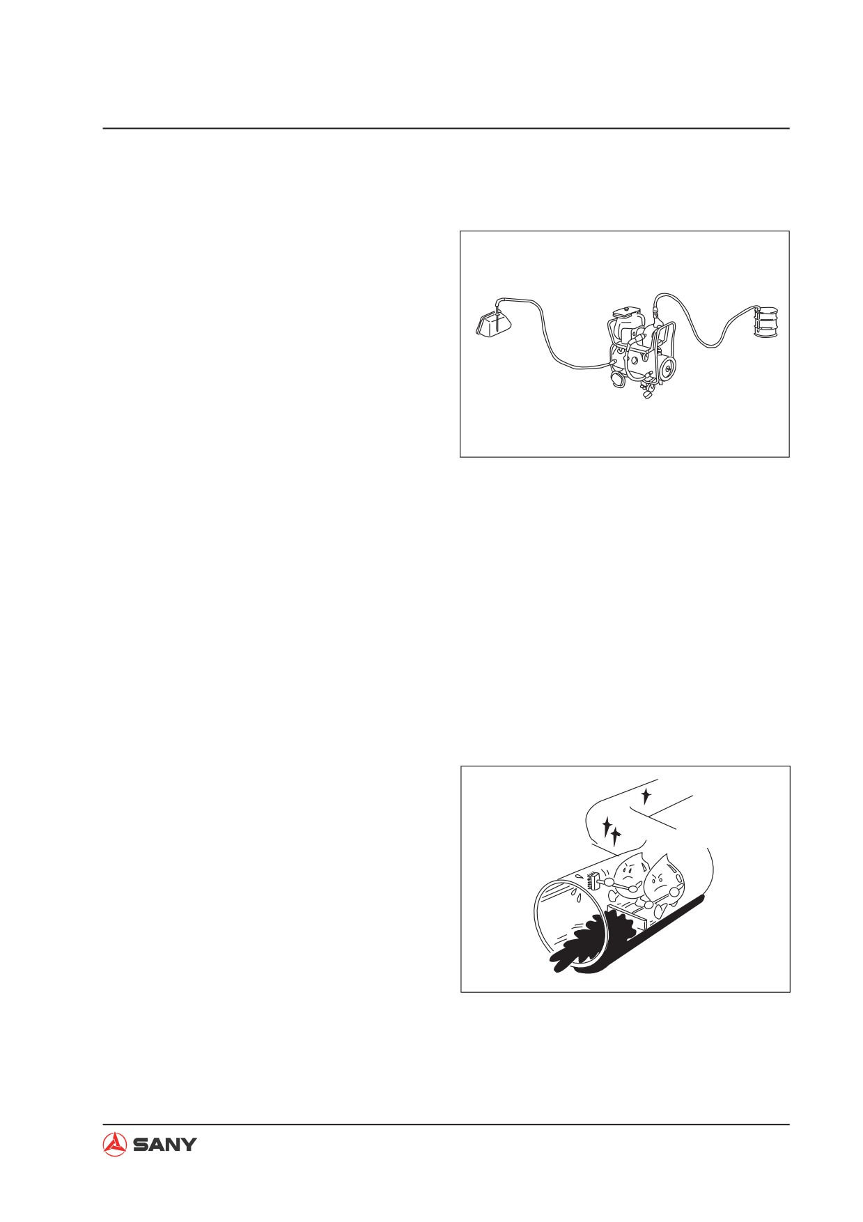
6.
Flushing operations
After disassembling and assembling the
equipment, or changing the oil, use flush-
Flushing oil
ing oil to remove the contaminants, sludge,
and old oil from the hydraulic circuit.
Normally, flushing is carried out twice:
primary flushing is carried out with flushing
oil, and secondary flushing is carried out
with the specified hydraulic oil.
ZX215-1000026
1-17
Introduction
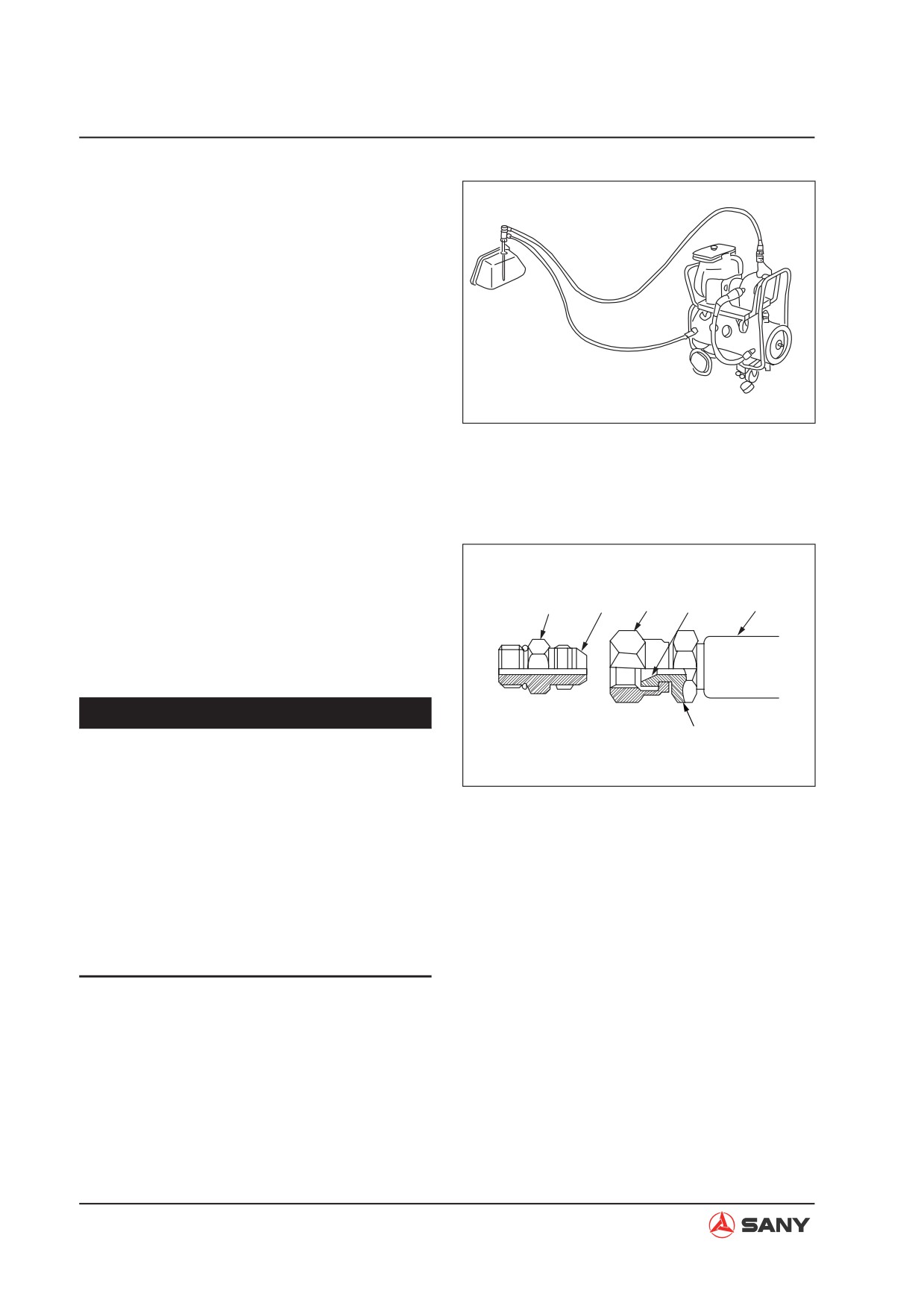
7. Cleaning operations
After repairing the hydraulic equipment
(pump, control valve, etc.) or when run-
ning the machine, carry out oil cleaning
to remove the sludge or contaminants in
the hydraulic oil circuit. The oil cleaning
equipment is used to remove the ultra fine
(about 3 ȝ) particles that the filter built in
the hydraulic equipment cannot remove, so
it is an extremely effective device.
ZX215-1000027
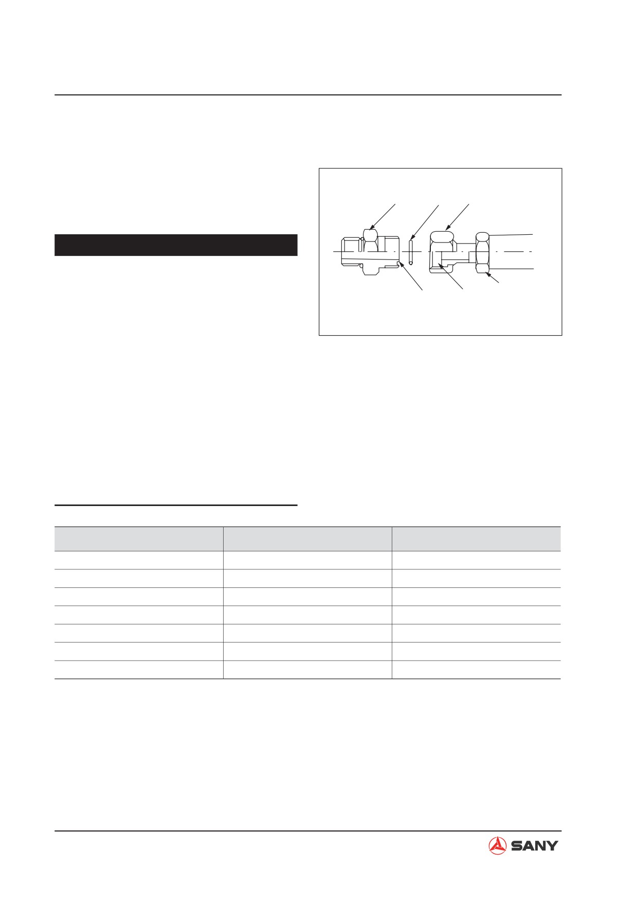
1.4 Hose Connector
Hose connector is used to connect hoses with
a small diameter. The metal sealing surface (4)
of the joint (1) must be in close contact with
1
4
3
5
2
the metal sealing surface (5) of the hose (2) to
seal pressurized oil.
NOTICE
Connector
Ɣ Do not over-tighten the nut (3). Exces-
sive force applied on the metal sealing
ZX215-1000028
surface (4) and (5) may cause the joint
(1) to break. Be sure to tighten nut (3)
according to technical specifications.
Ɣ Scratches or other damages on seal-
ing surface (4) and (5) may cause leaks
at the joint. Be extremely careful not
to damage the sealing surfaces during
connecting and disconnecting work.
1-18
Introduction
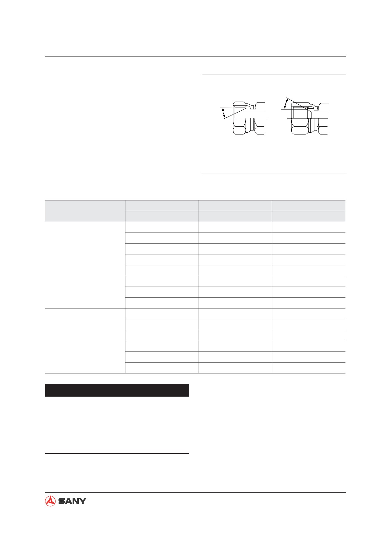
1.4.1 Type of hose connector
24°
24°
Male
Female
ZX215-1000029
1.4.2
Hose connector tightening torque table
Wrench size mm
Wrench size mm
Tightening torque
Type
Connecting nut
Hose joint
N·m(kgf·m,Ibf·ft)
19
19
59(6,44)
22
22
98(10,72)
27
27
118(12,87)
36
36
235(24,173)
24° Male
41
41
295(30,218)
50
50
490(50,361)
60
60
670(68,494)
70
70
980(100,723)
19
17
44(4.5,32)
22
19
59(6,44)
27
22
118(12,87)
24° Female
36
30, 32
235(24,173)
41
36
295(30,218)
50
46
490(50,361)
NOTICE
Ɣ
The torque values listed in the table are
intended for general application.
Ɣ
Do not use torque values listed in this
table when different torque values are
specified for a special purpose.
1-19
Introduction
1.4.3 Connection of O-rings
Place O-ring (6) in contact with the contact
surface of the joint (7) to seal the pressurized
oil.
7
6
9
NOTICE
Ɣ Replace o-rings (6) with new ones when
re-connecting hoses.
Hose connector
8
10
Ɣ Before tightening nut (9), make sure the
o-ring (6) has been placed into the o-ring
ZX215-1000030
seat (8).Displacement of the o-ring may
have it damaged and cause leaks.
Ɣ Be careful not to damage the o-ring seat
(8) or the sealing surface (10). Damaged
o-ring (6) may cause oil leakage.
Ɣ If oil leakage due to loosened nut (9) is
detected, do not try to stop the leakage
by tightening nut (9). Instead, replace o-
ring (6) with a new one and make sure it
is well positioned, and tighten nut (9).
Wrench size mm
Wrench size mm
Tightening torque
Connecting nut
Hose joint
N·m (kgf·m,Ibf·ft)
19
17
44(4.5,32)
22
19
59(6,44)
27
22
118(12,87)
36
30, 32
235(24,173)
41
36
295(30,218)
50
46
490(50,361)
1-20
Introduction
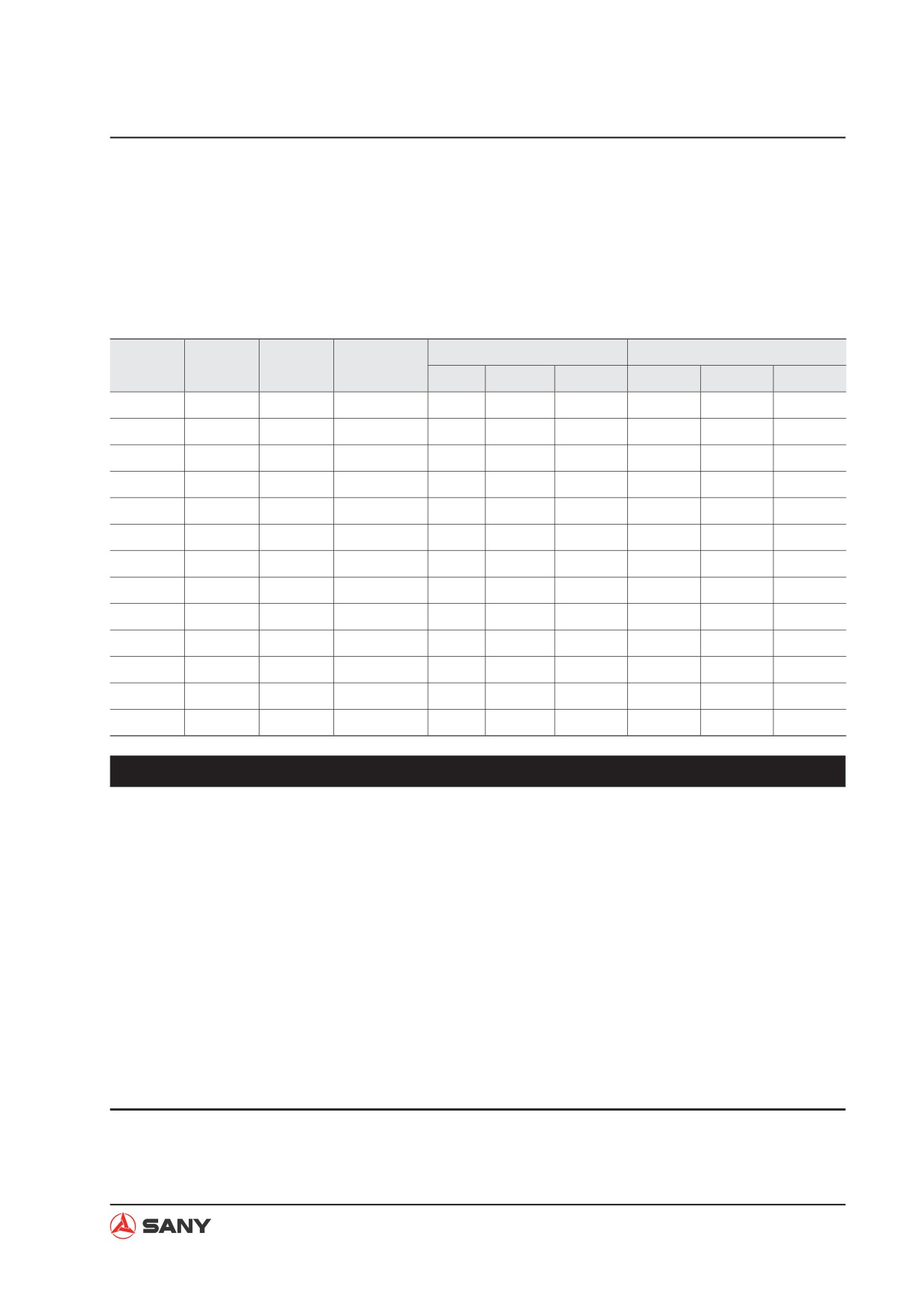
1.5 Table of Standard Tightening Torques
Table of tightening torques for bolts and nuts
Ɣ Unless specified otherwise, tighten metric nuts and bolts to the torque below. (When using
torque wrench)
Bolt
Bolt
Wrench
Hex wrench
Hexagonal bolt
Hexagonal socket head bolt
diameter
grade
size
size
N·m
kgf·m
lbf·ft
N·m
kgf·m
lbf·ft
M6
10.9
10
4
13.2
1.37
9.74
13.2
1.37
9.74
M8
10.9
13
6
31
3.16
22.87
31
3.16
22.87
M10
10.9
17
8
66
6.73
48.7
66
6.73
48.7
M12
10.9
19
10
113
11.53
83.39
113
11.53
83.39
M14
10.9
22
12
177
18.06
130.6
177
18.06
130.6
M16
10.9
24
14
279
28.47
205.9
279
28.47
205.9
M18
10.9
27
14
382
38.98
281.9
382
38.98
281.9
M20
10.9
30
17
549
56.02
405.16
549
56.02
405.16
M27
10.9
41
19
1320
134.7
974.16
1320
134.7
974.16
M10
12.9
17
6
78
7.96
57.76
78
7.96
57.76
M12
12.9
19
8
137
13.98
101.1
137
13.98
101.1
M16
12.9
24
14
339
34.6
250.18
339
34.6
250.18
M20
12.9
30
17
664
67.75
490
664
67.75
490
NOTICE
The following items apply to fine thread and coarse thread.
Ɣ Apply grease (zinc white B dissolved in spindle oil) onto the nuts and bolts to reduce
the friction coefficient. Thrust bolts do not require greasing.
Ɣ Torque tolerance is ±10%.
Ɣ Always use bolts of correct length. The tip of bolts with excessive length may contact
the bottom of the bolt hole, resulting in under-tightening. Bolts with inadequate length
may result in insufficient fastening.
Ɣ The torque values listed in the table are intended for general application. If different
torque values are specified for a special purpose, the torque values in this table are not
applicable any more.
Ɣ Make sure the threads are free of dirt or rusts before installation of nuts and bolts.
1-21
Introduction
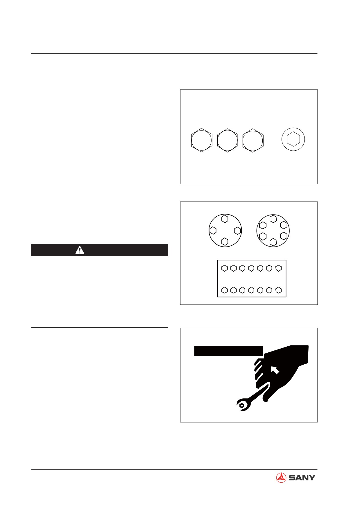
1.6 Type of Bolts
Tighten nuts and bolts properly to specified
torque values. The type and grade of bolts are
illustrated on the right.
Hex bolt
Socket head hex bolt
Use correct bolts and tighten them properly
when assembling machines or components.
8.8
10.9
12.9
ZX215-1000031
1.7 Tightening Sequence
When two or more bolts are being tightened,
Cross tightening
Diagonal tightening
follow the tightening sequence shown on the
1
1
right to ensure even tightening.
6
3
3
4
4
5
2
2
CAUTION
Central and diagonal tightening
Ɣ Always use suitable tools for specific
12
9
4
1
6
7
14
work. Use of improper tools and meth-
ods may cause a hazardous situation.
13
8
5
2
3
10
11
Ɣ Use tools of correct sizes when loosen-
ZX215-1000032
ing or tightening the nuts or bolts. Oth-
erwise, the tools may slide and cause
personal injury.
ZX215-1000033
1-22
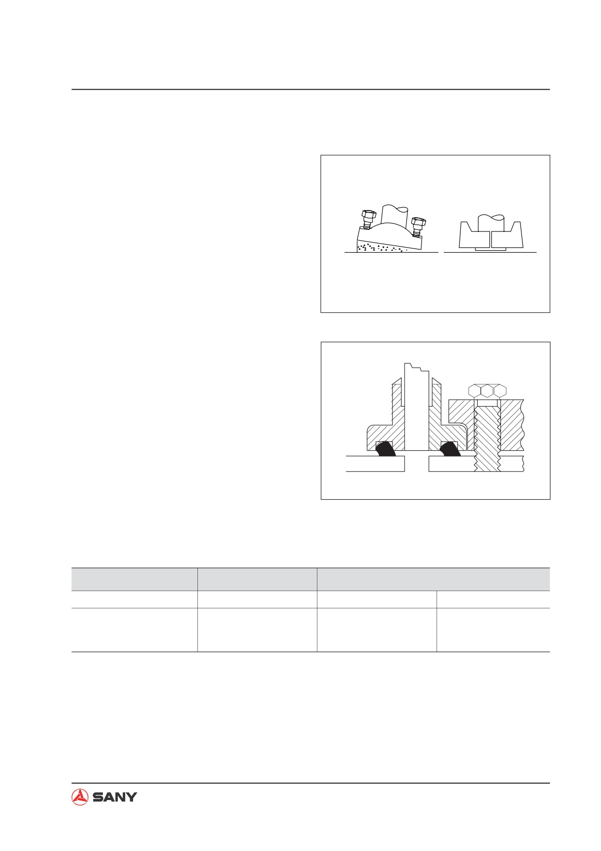
Introduction
1.8 Maintenance of Half Flanges
1. Clean the sealing surface of the flange and
check it carefully. Scratches and coarse-
ness cause leaks or abrasion of seals.
Uneven surface may squeeze the seal out.
If these faults are not corrected properly,
parts may have to be replaced.
2. Always use specified O-rings. Check that
the O-rings are not damaged. Do not file
the surface of the O-ring. Apply grease
ZX215-1000034
onto the O-ring to locate it.
3. Tighten the half flanges carefully. Locate
the opening at the center so that it is per-
pendicular to the oil opening. Tighten the
Improper
bolt manually to maintain the location of
the components.
ZX215-1000035
1.8.1 Table of tightening torques for half flange bolts
Ɣ Unless specified otherwise, tighten the half flange bolts to the torques below.
Thread diameter of bolt
Width across flats
Tightening torque
mm
mm
Nm
kgm
10
14
59~74
6.0~7.5
12
17
98~123
10.0~12.5
16
22
235~285
23.5~29.5
1-23
Introduction
1.9 Conversion Table
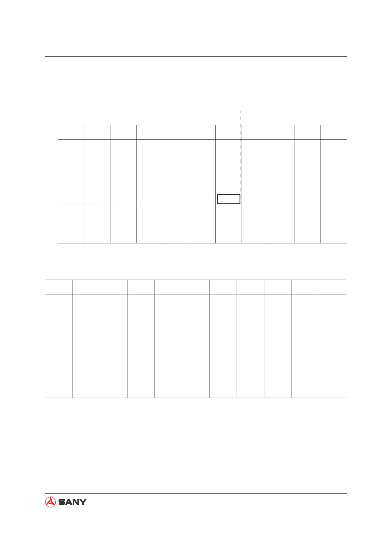
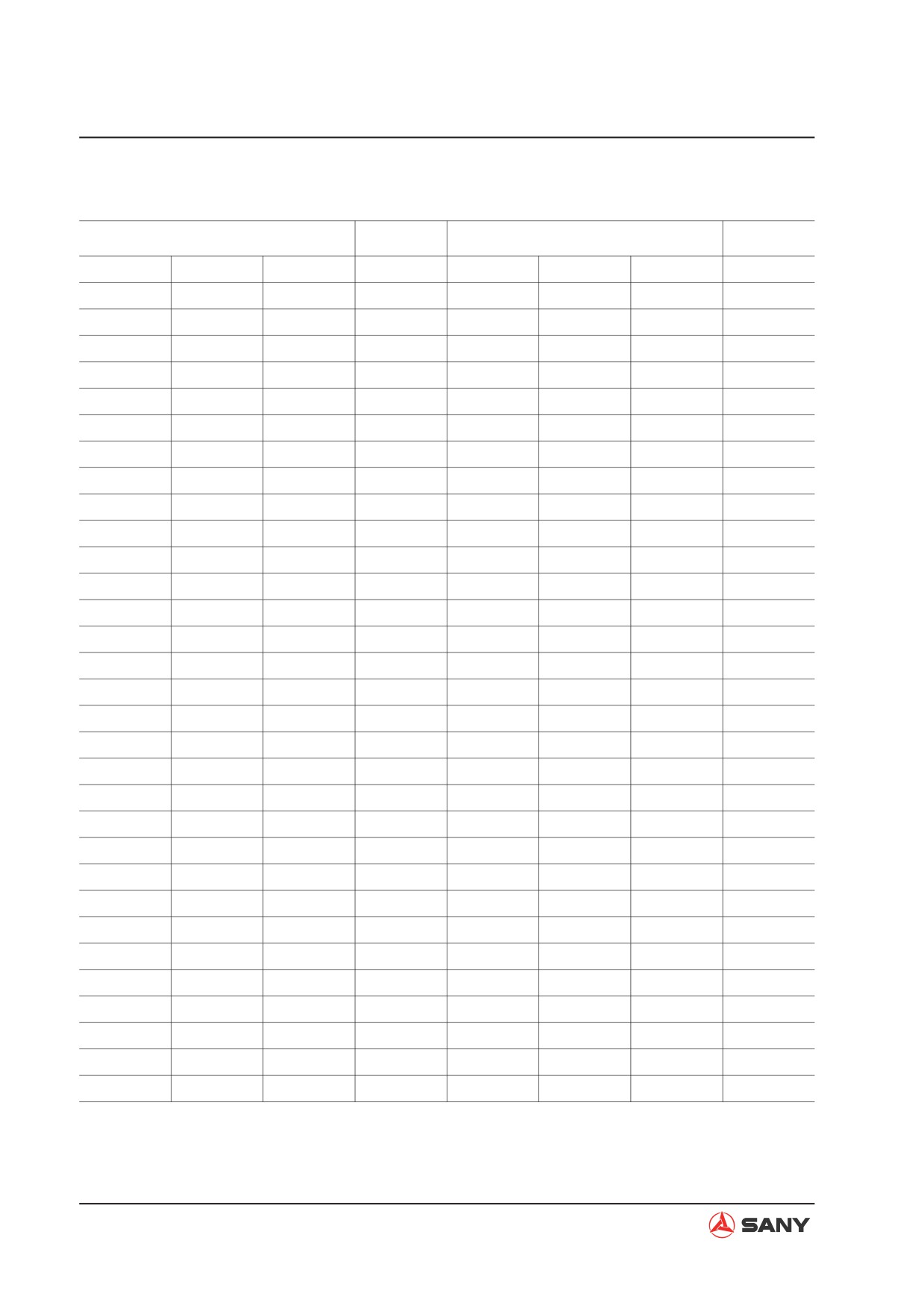
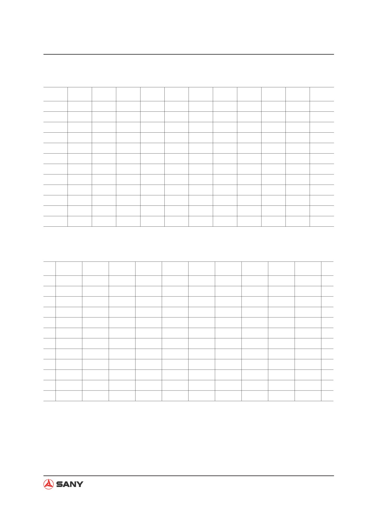
The conversion table in this section is provided to enable simple conversion of figures. For details
of the method of using the conversion table, see the example given below.
Example:
Method of using the conversion table to convert from millimeters to inches
1. Convert 55 mm into inches
1) Locate the number 50 in the vertical column at the left side, take this as (A), and then draw
a horizontal line from (A).
2) Locate the number 5 in the row across the top, take this as (B), then draw a perpendicular
line down from (B).
3) Take the point where the two lines cross as (C). This point (C) gives the value when con-
verting from millimeters to inches. Therefore, 55 mm = 2.165 inches.
2. Convert 550 mm into inches
1) The number 550 does not appear in the table, so divide it by 10 (move the decimal point
one place to the left) to convert it to 55 mm.
2) Carry out the same procedure as above to convert 55 mm to 2.165 inches.
3) The original value (550 mm) was divided by 10, so multiply 2.165 inches by 10 (move the
decimal point one place to the right) to return to the original value. This gives 550 mm =
21.65 inches.
1-24
Introduction
Length
Millimeters to Inches
1mm=0.03937in
(B)
0
1
2
3
4
5
6
7
8
9
0
0.000
0.039
0.079
0.118
0.157
0.197
0.236
0.276
0.315
0.354
10
0.394
0.433
0.472
0.512
0.551
0.591
0.630
0.669
0.709
0.748
20
0.787
0.827
0.866
0.906
0.945
0.984
1.024
1.063
1.102
1.142
30
1.181
1.220
1.260
1.299
1.339
1.378
1.417
1.457
1.496
1.535
40
1.575
1.614
1.654
1.693
1.732
1.772
1.811
1.850
1.890
1.929
(C)
50
1.969
2.008
2.047
2.087
2.126
2.165
2.205
2.244
2.283
2.323
(A)
60
2.362
2.402
2.441
2.480
2.520
2.559
2.598
2.638
2.677
2.717
70
2.756
2.795
2.835
2.874
2.913
2.953
2.992
3.031
3.071
3.110
80
3.150
3.189
3.228
3.268
3.307
3.346
3.386
3.425
3.465
3.504
90
3.543
3.583
3.622
3.661
3.701
3.740
3.780
3.819
3.858
3.898
Millimeters to Inches
1mm=0.03937in
0
1
2
3
4
5
6
7
8
9
0
0
0.039
0.079
0.118
0.157
0.197
0.236
0.276
0.315
0.354
10
0.394
0.433
0.472
0.512
0.551
0.591
0.630
0.669
0.709
0.748
20
0.787
0.827
0.866
0.906
0.945
0.984
1.024
1.063
1.102
1.142
30
1.181
1.220
1.260
1.299
1.339
1.378
1.417
1.457
1.496
1.535
40
1.575
1.614
1.654
1.693
1.732
1.772
1.811
1.850
1.890
1.929
50
1.969
2.008
2.047
2.087
2.126
2.165
2.205
2.244
2.283
2.323
60
2.362
2.402
2.441
2.480
2.520
2.559
2.598
2.638
2.677
2.717
70
2.756
2.795
2.835
2.874
2.913
2.953
2.992
3.031
3.071
3.110
80
3.150
3.189
3.228
3.268
3.307
3.346
3.386
3.425
3.465
3.504
90
3.543
3.583
3.622
3.661
3.701
3.740
3.780
3.819
3.858
3.898
1-25
Introduction
Inches to Millimeters
in.
mm
in.
mm
1/64
0.3969
33/64
13.0969
1/32
0.7938
17/32
13.4938
3/64
1.1906
35/64
13.8906
1/16
1.5875
9/16
14.2875
5/64
1.9844
37/64
14.6844
3/32
2.3813
19/32
15.0813
7/64
2.7781
39/64
15.4781
1/8
3.1750
5/8
15.8750
9/64
3.5719
41/64
16.2719
5/32
3.9688
21/32
16.6688
11/64
4.3656
43/64
17.0656
3/16
4.7625
11/16
17.4625
13/64
5.1594
45/64
17.8594
7/32
5.5563
23/32
18.2563
15/64
5.9531
47/64
18.6531
1/4
6.3500
3/4
19.0500
17/64
6.7469
49/64
19.4469
9/32
7.1438
25/32
19.8438
19/64
7.5406
51/64
20.2406
5/16
7.9375
13/16
20.6375
21/64
8.3344
53/64
21.0344
11/32
8.7313
27/32
21.4313
23/64
9.1281
55/64
21.8281
3/8
9.5250
7/8
22.2250
25/64
9.9219
57/64
22.6219
13/32
10.3188
29/32
23.0188
27/64
10.7156
59/64
23.4156
7/16
11.1125
15/16
23.8125
29/64
11.5094
61/64
24.2094
15/32
11.9063
31/32
24.6063
31/64
12.3031
63/64
25.0031
1/2
12.7000
1
25.4000
1-26
Introduction
Feet to Meters
ft.
0
1
2
3
4
5
6
7
8
9
ft.
m
m
m
m
m
m
m
m
m
m
-
-
0.305
0.610
0.914
1.219
1.524
1.829
2.134
2.438
2.743
-
10
3.048
3.353
3.658
3.962
4.267
4.572
4.877
5.182
5.486
5.791
10
20
6.096
6.401
6.706
7.010
7.315
7.620
7.925
8.230
8.534
8.839
20
30
9.144
9.449
9.754
10.058
10.363
10.668
10.973
11.278
11.582
11.887
30
40
12.192
12.497
12.802
13.106
13.411
13.716
14.021
14.326
14.630
14.935
40
50
15.240
15.545
15.850
16.154
16.459
16.764
17.069
17.374
17.678
17.983
50
60
18.288
18.593
18.898
19.202
19.507
19.812
20.117
20.422
20.726
21.031
60
70
21.336
21.641
21.946
22.250
22.555
22.860
23.165
23.470
23.774
24.079
70
80
24.384
24.689
24.994
25.298
25.603
25.908
26.213
26.518
26.822
27.127
80
90
27.432
27.737
28.042
28.346
28.651
28.956
29.261
29.566
29.870
30.175
90
100
30.480
30.785
31.090
31.394
31.699
32.004
32.309
32.614
32.918
33.223
100
Meters to Feet
m
0
1
2
3
4
5
6
7
8
9
m
ft.
ft.
ft.
ft.
ft.
ft.
ft.
ft.
ft.
ft.
-
-
3.2808
6.5617
9.8425
13.1234
16.4042
19.6850
22.9659
26.2467
29.5276
-
10
32.8084
36.0892
39.3701
42.6509
45.9318
49.2126
52.4934
55.7743
59.0551
62.3360
10
20
65.6168
68.8976
72.1785
75.4593
78.7402
82.0210
85.3018
88.5827
91.8635
95.1444
20
30
98.4252
101.7060
104.9869
108.2677
111.5486
114.8294
118.1102
121.3911
124.6719
127.9528
30
40
131.2336
134.5144
137.7953
141.0761
144.3570
147.6378
150.9186
154.1995
157.4803
160.7612
40
50
164.0420
167.3228
170.6037
173.8845
177.1654
180.4462
183.7270
187.0079
190.2887
193.5696
50
60
196.8504
200.1312
203.4121
206.6929
209.9738
213.2546
216.5354
219.8163
223.0971
226.3780
60
70
229.6588
232.9396
236.2205
239.5013
242.7822
246.0630
249.3438
252.6247
255.9055
259.1864
70
80
262.4672
265.7480
269.0289
272.3097
275.5906
278.8714
282.1522
285.4331
288.7139
291.9948
80
90
295.2756
298.5564
301.8373
305.1181
308.3990
311.6798
314.9606
318.2415
321.5223
324.8032
90
100
328.0840
331.3648
334.6457
337.9265
341.2074
344.4882
347.7690
351.0499
354.3307
357.6116
100
1-27
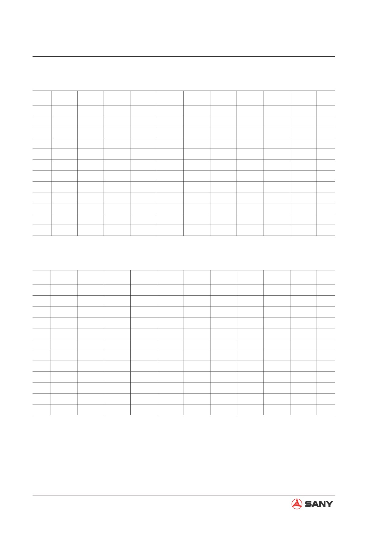
Introduction
Miles to Kilometers
miles
0
1
2
3
4
5
6
7
8
9
miles
km
km
km
km
km
km
km
km
km
km
-
-
1.609
3.219
4.828
6.437
8.047
9.656
11.265
12.875
14.484
-
10
16.093
17.703
19.312
20.921
22.531
24.140
25.749
27.359
28.968
30.577
10
20
32.187
33.796
35.405
37.015
38.624
40.234
41.843
43.452
45.062
46.671
20
30
48.280
49.890
51.499
53.108
54.718
56.327
57.936
59.546
61.155
62.764
30
40
64.374
65.983
67.592
69.202
70.811
72.420
74.030
75.639
77.248
78.858
40
50
80.467
82.077
83.686
85.295
86.904
88.514
90.123
91.732
93.342
94.951
50
60
96.561
98.170
99.779
101.388
102.998
104.607
106.216
107.826
109.435
111.044
60
70
112.654
114.263
115.872
117.482
119.091
120.701
122.310
123.919
125.529
127.138
70
80
128.748
130.357
131.966
133.575
135.185
136.794
138.403
140.013
141.622
143.231
80
90
144.841
146.450
148.059
149.669
151.278
152.887
154.497
156.106
157.715
159.325
90
100
160.934
162.543
164.153
165.762
167.371
168.981
170.590
172.199
173.809
175.418
100
Kilometers to Miles
km
0
1
2
3
4
5
6
7
8
9
km
miles
miles
miles
miles
miles
miles
miles
miles
miles
miles
-
-
0.621
1.243
1.864
2.485
3.107
3.728
4.350
4.971
5.592
-
10
6.214
6.835
7.456
8.078
8.699
9.321
9.942
10.563
11.185
11.806
10
20
12.427
13.049
13.670
14.292
14.913
15.534
16.156
16.777
17.398
18.020
20
30
18.641
19.262
19.884
20.505
21.127
21.748
22.369
22.991
23.612
24.233
30
40
24.855
25.476
26.098
26.719
27.340
27.962
28.583
29.204
29.826
30.447
40
50
31.069
31.690
32.311
32.933
33.554
34.175
34.797
35.418
36.039
36.661
50
60
37.282
37.904
38.525
39.146
39.768
40.389
41.010
41.632
42.253
42.875
60
70
43.496
44.117
44.739
45.360
45.981
46.603
47.224
47.845
48.467
49.088
70
80
49.710
50.331
50.952
51.574
52.195
52.816
53.438
54.059
54.681
55.302
80
90
55.923
56.545
57.166
57.787
58.409
59.030
59.652
60.273
60.894
61.516
90
100
62.137
62.758
63.380
64.001
64.622
65.244
65.865
66.487
67.108
67.729
100
1-28