Api Pneumatic. GENERAL CATALOG (2019) - page 3
 

  Index      Manuals     Api Pneumatic. GENERAL CATALOG (2019)


Search            copyright infringement  


Content      ..     1      2      3      4      ..


Api Pneumatic. GENERAL CATALOG (2019) - page 3


1.5.103

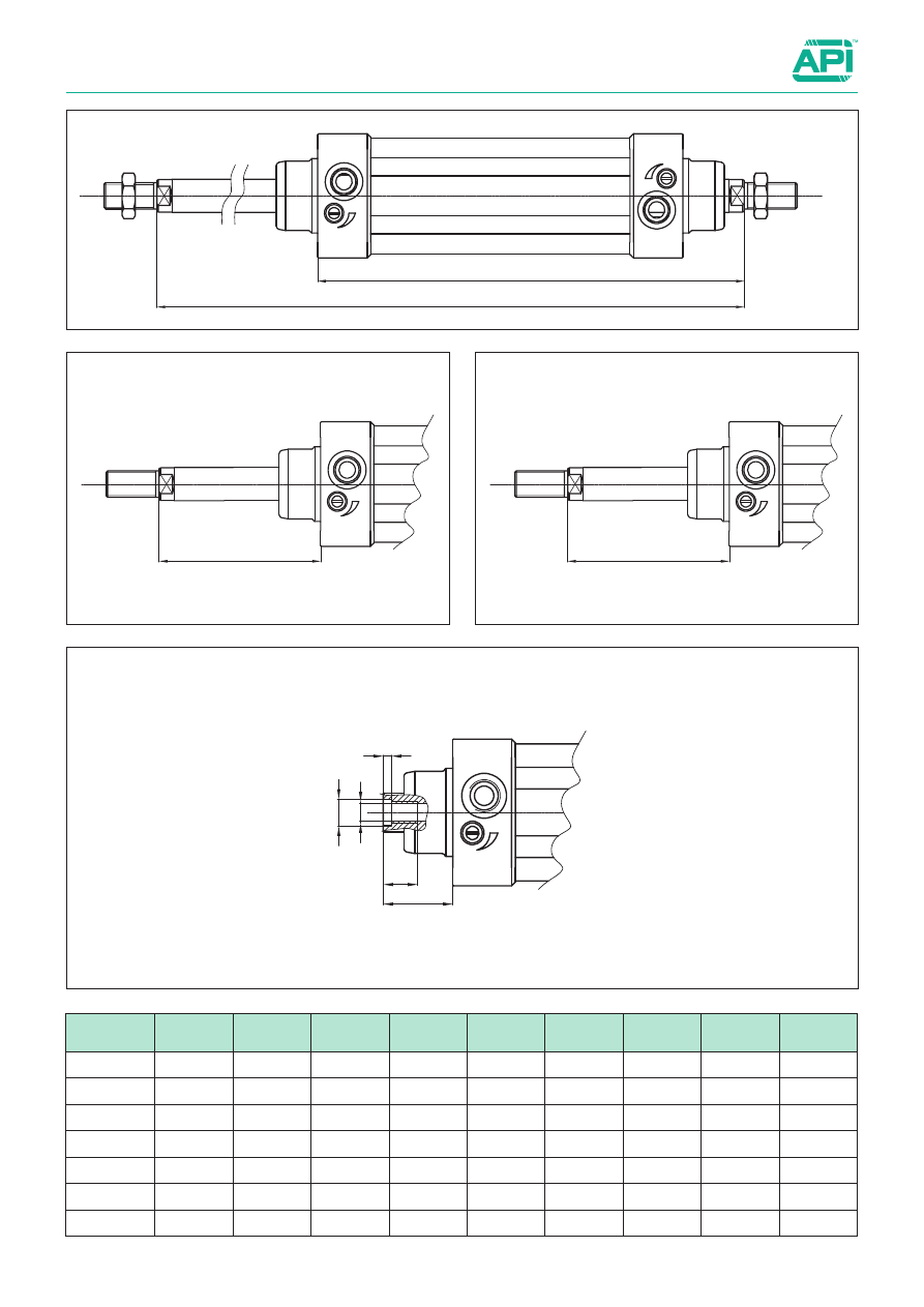
Cylinders ISO 15552

Bores from  32 to 125 mm


Options

Type: 

...P

Type: 

...B

Type: 

...B1

Type: 

...F

ZJ + Stroke

ZM + 2 Stroke

WH

WH1

WF

AF

T4

KF

GF

Ø 

mm

AF

GF

KF

T4

WF

WH

WH1

ZJ

ZM

32

12

8

M6

2,6

26

74

99

120

146

40

12

10

M8

3,3

30

85

106

135

165

50

16

12

M10

4,7

37

107

127

143

180

63

16

12

M10

4,7

37

107

129

158

195

80

20

14

M12

6,1

46

136

156

174

220

100

20

14

M12

6,1

51

143

181

189

240

125

32

18

M16

8

65

187

-

225

290
1

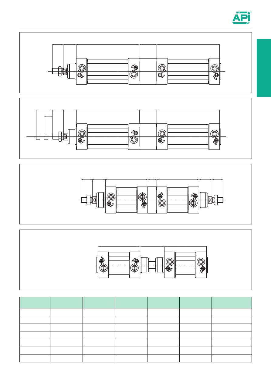
Cylinders ISO 15552

Bores from  32 to 125 mm


Options

1.5.104

Type: 

...TA1

Type: 

...TA2

Type: 

...TA3

Type: 

...TA4

L8 + Stroke

L8 + Stroke

B

WH

AM

L8 + Stroke2

L8 + Stroke1

B

WH

AM

Stroke2

Stroke1

L8 + Stroke1

L8 + Stroke2

C

WH

AM

WH

AM

L8 + Stroke1

L8 + Stroke2

D

Ø 

mm

AM

B

C

D

L8

WH

32

22

40

12

48

94

26

40

24

44

12

54

105

30

50

32

52

16

69

106

37

63

32

50

16

69

121

37

80

40

64

20

86

128

46

100

40

76

20

91

138

51

125

54

80

35

120

160

65

1.5.105

Cylinders ISO 15552

Bores from  32 to 125 mm


Mounting accessories ISO

For dimensions and codes of the accessories: see page 1.97.1

Rear clevis/eye

Flange

Feet

Centre trunnion

Rear standard hinge

Rear 90° hinge

XD + stroke

  ZF + stroke

  W

XA + stroke

SA + stroke

  AH

  XVmax + stroke

  XVmin.

  A max

XD + stroke

B

XD + stroke

C

  D

Ø 

mm

max

AH

B

C

D

SA

W

XA

XD

XV 

min

XV 

max

ZF

32

70

32

22

21

32

142

16

144

142

60

86

130

40

78

36

25

24

36

161

20

163

160

69

96

145

50

91

45

27

33

45

170

25

175

170

78

102

155

63

94

50

32

37

50

185

25

190

190

82

113

170

80

130

63

36

47

63

210

30

215

210

97

123

190

100

145

71

41

55

71

220

35

230

230

107

133

205

125

170

90

50

70

90

250

45

270

275

126,5

163,5

245

1

1.8.1

Cylinders ISO 15552

Bores from  160 to 320 mm


Double acting 

New series  of cylinders conforming to ISO 15552 standards.
External tie-rods and round anodised aluminium tube.
The main features of this cylinder are the modern design and 
the attention to details.

For the magnetic reed switches 
type ASV 

see from page 1.110.1.

For coupling cylinders/reed 
swiches/brackets 

see table on page 1.120.5

For mounting accessories 

see from page 1.97.1.

For rod accessories 

see from page 1.85.1.

The options can be combined (when this is possible).
The suffix of the options are to be added to the model number of the standard product, as shown in the following table.

How to order: 160 / 100 AMTKVR-M20x1,5

On request, they can be supplied 

according to 2014/34/EU - 

ATEX

II 2Gc IIC T5
II 2Dc T100°C

Options

Suffix

Through rod (page 1.8.4)

P

Rod in stainless steel AISI 304

K

Seals FKM -20°C ÷ +150°C

V

Scraper ring only FKM -20°C ÷ +80°C   

V1

Low temperature seals -40°C ÷ +80°C

BT

Tandem forward movement piston rods coupled together  

(page 1.8.5)

TA1

Tandem forward movement piston rods independent  

(page 1.8.5)

TA2

Tandem back to back 

(page 1.8.5)

TA3

Tandem front to front 

(page 1.8.5)

TA4

Extended rod (indicate the requested WH dimension in mm. E.g.: WH -100)

WH-...

Without adjustable cushionings

D

Adjustable rear cushioning only

D1

Adjustable front cushioning only

D2

Special male thread (indicate the requested thread. E.g. : R-M 10x1,5).
The dimension AM of the special thread will be the same as the standard. The cylinder will be supplied without rod nut.

R-M...

Female thread; for dimensions see page 1.8.4

F

With bellows for protection of the rod (in this case the dimension WH will be extended according the stroke of the cylinder)

Z

NBR seals 

H

Piston rod tightness in nitrile rubber NBR with retainer ring

H1

Brass rod scraper (with V, V1 and H options only)

Y

Stainless steel AISI 316L profile tube

TX

Special on request

/S

160

/

100

AMT

K

V

R-M20x1,5

Bore

/

Stroke

Type

Option

Option

Option

Standard executions

Version

Symbol

Type

Magnetic Standard 

AMT

1.8.2

Cylinders ISO 15552

Bores from  160 to 320 mm


Technical data

Materials (standard types)

1

  Rod

Chrome-plated steel C45

2

  Bushing

Self-lubricating sintered bronze

3

  Heads

Die-cast painted aluminium

4

  Tube

Anodised aluminium

5

  Piston

Die-cast aluminium

6

  Guide ring

Natural Delrin

7

  Cushioning adjustment screw

Stainless steel AISI 303

8

  Rod seals

Polyurethane

Other seals

Nitrile rubber NBR/polyurethane

Technical data

Bore (mm)

160

200

250

320

Fluid

Compressed filtered air with or without lubrication. Lubrication, if started, must be continued.

Pressure

1 ÷ 10 bar

Temperature range

-20°C ÷ +80°C (standard / V1)

-20°C ÷ +150°C (V)

-40°C ÷ +80°C (BT)

Stroke

from 10 mm to 2500 mm

Cushion lenght

46

47

40

40

Ports

3/4”

1”

Rod thread

M36 x 2

M42 x 2

M48 x 2

Weight

Stroke zero (g)

11507

14532

26811

47996

Additional 10 mm 
stroke (g)

234

250

384

597

1

Ø 

(mm)

AM

Ø d11

BG

E

EE

J2

J3

KK

L1

L2

H

160

72

65

24

180

3/4"

15

15

M36x2

50

180

14

200

72

75

24

220

3/4"

15

15

M36x2

65

180

14

250

84

90

25

270

1"

25

25

M42x2

75

200

20

320

96

110

30

350

1"

35

35

M48x2

90

220

17

1.8.3

Cylinders ISO 15552

Bores from 160 to 320 mm


Standard dimensions

ZJ+stroke

L2+stroke

Type: AMT

1  cushioning adjustament screw

How to order:

 200 / SG / AMT

Seals kits

n. 1

Rod seal

n. 2

Cushioning seal

n. 2

Piston lip-seal

n. 1

Linear rubber ring for piston (damper)

n. 2

Tube O-ring

n. 1

Piston guiding ring

n. 2

O-ring for cushioning screw

n. 1

O-ring to seal two semi-pistons

200

/

SG

/

AMT

Bore 

/

Seal kit

/

Type

Ø (mm)

L7

MM 

Ø f7

PL

RT

TG

VA

VD

WH

ZJ

1

2

160

32

40

25

M16

140

6

8

80

266

36

55

25

3,7

200

34

40

25

M16

175

6

25

95

281

36

55

25

3,7

250

40

50

30

M20

220

8

25

105

313

46

65

32

5,5

320

45

63

30

M24

270

10

25

120

350

55

75

36

5,5

1.8.4

Cylinders ISO 15552

Bores from 160 to 320 mm


Options

ZJ+stroke

ZM+2strokes

Type: 

...P

Type: 

...F

Ø 

mm

AF

KF

T4

WF

GF

ZJ

ZM

160

36

M20

10

80

22

260

340

200

36

M20

10

95

22

275

370

250

40

M24

12

105

26

305

410

320

50

M30

15

120

32

340

460

1

Cylinders ISO 15552

Bores from 160 to 320 mm


Options

Type: 

...TA1


Type: 

...TA2

stroke

stroke

Type: 

...TA3

Type: 

...TA4

1.8.5

Ø 

mm

AM

B

C

D

L8

WH

160

72

100

50

152

180

80

200

72

130

50

167

180

95

250

84

150

60

180

200

105

320

96

180

70

200

220

120

Cylinders ISO 15552

Bores from 160 to 320 mm


Mounting accessories ISO

Rear clevis/eye

Flange

Feet

Centre trunnion

Rear standard hinge

Rear 90° hinge

1.8.6

Ø 

mm

max

AH

B

C

D

SA

W

XA

XD

XV 

min

XV 

max

ZF

160

190

115

55

88

115

300

60

320

315

150

190

280

200

240

135

60

90

135

320

70

345

335

165

205

300

250

296

165

70

110

165

350

80

380

375

185

225

330

320

380

200

80

122

200

390

90

425

420

207

253

370

1

1.11.1

Round Cylinders

Bores from 32 to 63 mm

, with stainless steel tube 


Single and double acting

Series of cylinders not conforming to standards.
The heads are connected with the body through rolling: this 
guarantees perfect tightening.
Dumpers are in nitrile rubber to cushion the impact of the piston. 
RDMA type are provided with adjustable cushionings at both ends.
The standard cylinders are provided with rod nut.
One or more magnetic reed switches can be applied to the 
magnetic types.
For the magnetic reed switches type ASV see from page 1.110.1.
For mounting accessories 

see from page 1.96.1.

For rod accessories 

see from page 1.85.5.

How to order: 40 / 50 RDMP

40

/

50

RDM

P

Bore

/

Stroke

Type

Option

On request, they can be supplied 

according to 2014/34/EU - 

ATEX

II 2Gc IIC T5
II 2Dc T100°C

The options can be combined (when this is possible)

Options 

Suffix

Through rod

P

Rear spring

T

Seals FKM

-20°C ÷ +150°C

V

Low temperature seals

-40°C ÷ +80°C

BT

Low friction

L

Special versions on request

/ S

Standard executions

Version

Symbol

Type

Single acting

RS

Double acting

RD

Double acting magnetic

RDM

Double acting magnetic 
with cushionings

RDMA

Technical data

Fluid

Compressed filtered air with or without lubrication. Lubrication, if started, must be continued.

Pressure

max 10 bar

Temperature range

-30°C ÷ +80°C (standard) 

-20°C ÷ +150°C (V)

-40°C ÷ +80°C (BT)

Materials

Heads: 

Anodised aluminium 

Tube: 

Stainless Steel AISI 304

Rod: 

Stainless Steel AISI 303

Piston: Aluminium 
Seals: Polyurethane

See page 1.1.3 to calculate the double acting cylinder force.
Seal kits not available for these cylinders.

Bore 

(mm)

Standard strokes 

(mm)

Max stroke 

(mm)

32

25, 50, 80,100, 

125, 160, 200, 
250, 320, 400, 

500

1000

40

50

63

Double acting

Bore 

(mm)

Standard strokes 

(mm)

Max stroke 

(mm)

Thrust force

at 6 bar

(N)

Thrust force of the spring (N)

Stroke 10

Stroke 25

Stroke 50

min.

max

min.

max

min.

max

32

10, 25, 50

50

482

57

62

51

62

40

62

40

754

98

105

86

105

64

105

50

1178

147

158

130

158

101

158

63

1869

147

158

130

158

101

158

Single acting

New

V

L1 + stroke

L + stroke

H

Q

D

P

L3 + stroke

G

V

1

L2 + stroke

1.11.2

Round Cylinders

Bores from 32 to 63 mm


Standard dimensions and mountings

Ø mm

L

L

1

L

2

L

3

V

V

1

P

H

Q

G

D

32

148

124

125

125

48

47

20

40

24

51

7

40

153

153

146

146

60

57

27

50

30

61

9

50

160

160

158

158

64

62

30

54

34

75

9

63

164

164

161

161

65

63

34

65

35

92

9

Type: 

RS

High foot

Rear clevis

Pivot

Ø mm

V

F

P

D

F

1

R

L

2

Z

Z

1

W

L

1

L

R

1

H

S

SW

32

20

M30x1,5

30

1/8”

M10x1,5

12

78

14

38

96

47

148

33,6

17,5

6

17

40

24

M38x1,5

35

1/4”

M12x1,75

16

89

16

45

113

57

174

41,6

21

7

19

50

32

M45x1,5

38

1/4”

M16x2

20

96

18

50

120

62

188

52,4

26,5

8

24

63

32

M45x1,5

38

3/8”

M16x2

20

98

18

50

124

63

192

65,4

32,5

8

24

Type: 

RD-RDM-RDMA

1

Round Cylinders

Bores from 32 to 50 mm


Double acting

Series of cylinders not conforming to standards
The heads are connected with the body through thread; 
this guarantees perfect tightening.
The cushionings are in nitrile rubber to relieve the impact of the 
piston.
The standard cylinders are provided with rod nut.
One or more magnetic reed switches can be applied to the 
magnetic type.
For the magnetic reed switches type ASV see from page 1.110.1.
For mounting accessories 

see from page 1.96.1.

For rod accessories 

see from page 1.85.5.

How to order: 40 / 50 REDMP

40

/

50

REDM

P

Bore

/

Stroke

Type

Option

The options can be combined (when this is possible)

1.11.10

See page 1.1.3 to calculate the double acting cylinder force.
Seal kits not available for these cylinders.

On request, they can be supplied 

according to 2014/34/EU - 

ATEX

II 2Gc IIC T5
II 2Dc T100°C

Options 

Suffix

Through rod

P

Seals FKM

(for RED type only)

-20°C ÷ +150°C

V

Special versions on request

/ S

Bore 

(mm)

Standard strokes 

(mm)

Max stroke 

(mm)

32

25, 50, 80,100, 

125, 160, 200, 
250, 320, 400, 

500

1000

40

50

Standard executions

Version

Symbol

Type

Double acting

RED

Double acting magnetic

REDM

Technical data

Fluid

Compressed filtered air with or without lubrication. Lubrication, if started, must be continued.

Pressure

max 10 bar

Temperature range

-30°C ÷ +80°C (standard) 

-20°C ÷ +150°C (V) 

Materials

Heads: 

Anodised aluminium 

Tube: 

Anodised aluminium 

Rod: 

Chrome-plated steel C45 

Seals: 

Polyurethane - NBR

1.11.11

Round Cylinders

Bores from 32 to 50 mm


Standard dimensions and mountings

V

L1 + stroke

L + stroke

H

Q

D

P

L3 + stroke

G

V

1

L2 + stroke

Ø mm

L

L

1

L

2

L

3

V

V

1

P

H

Q

G

D

32

148

124

125

125

48

47

20

40

24

51

7

40

178

153

146

146

60

57

27

50

30

61

9

50

190

160

158

158

64

62

30

54

34

75

9

Type: 

RED-REDM

High foot

Rear clevis

Pivot

Ø mm

V

F

P

D

F

1

R

L

2

Z

Z

1

W

L

1

L

R

1

H

S

SW

32

20

M 30x1,5

30

1/8”

M10x1,5

12

78

14

38

96

47

148

36

17,5

6

17

40

24

M 38x1,5

35

1/4”

M12x1,75

16

89

16

45

113

57

174

45

21

7

19

50

32

M 45x1,5

38

1/4”

M16x2

20

96

18

50

120

62

188

55

26,5

8

24

1

Cylinders CNOMO 

Bores from 25 to 200 mm


Double acting

Series of cylinders conforming to CNOMO standards.
They are provided with a round barrel and external tie rods for
the bores from 25 to 200 mm.

The standard cylinders are provided with adjustable cushionings 
at both ends.

For reed switches ASV 

see page 1.110.1

For mounting accessories 

see from page 1.99.1

For rod accessories 

see from page 1.85.10.

The options can be combined (when this is possible).
The suffix of the options are to be added to the model number of the standard product, as shown in the following table.

How to order: 50/200CMV

1.14.1

How to order: 50 / SG / CX

How to order: 50 / SG / CM

On request, they can be supplied 

according to 2014/34/EU - 

ATEX

II 2Gc IIC T5
II 2Dc T100°C

Options

Suffix

Through rod

P

Stainless Steel AISI 304 rod

K

Seals FKM -20°C ÷ +150°C (for CM type only)

V

Scraper ring only FKM -20°C ÷ +80°C   

V1

Tandem forward movement piston rods coupled together

TA1

Tandem forward movement piston rods independent

TA2

Tandem back to back

TA3

Tandem front to front 

TA4

Special length of front tie-rods (indicate the requested length. Ex: T1 = 25). The thread will remain standard

T1

Special length of rear tie-rods  (indicate the requested length. Ex: T2 = 25). The thread will remain standard

T2

Special on request

/S

Without adjustable cushionings

D

Adjustable rear cushioning only

D1

Adjustable front cushioning only

D2

50

/

200

CM

V

Bore

/

Stroke

Type

Option

50

/

SG

/

CX

Bore 

/

Seal kit

/

Type

50

/

SG

/

CM

Bore 

/

Seal kit

/

Type

Seals kits

n. 1

Rod seal

n. 2

Cushioning seal

n. 1

Piston monobloc

n. 2

Tube O-ring

n. 2

O-ring for cushioning screw

n. 2

O-ring to seal two semi-pistons

Seals kits

n. 1

Rod seal

n. 2

Cushioning seal

n. 2

Piston lip-seal

n. 2

Tube O-ring

n. 1

Piston guiding ring

n. 2

O-ring for cushioning screw

n. 2

O-ring to seal two semi-pistons

Standard executions

Version

Symbol

Type

Non magnetic

boser from 32 to 100

CX

Magnetic

bore from 25 to 200

CM

Cylinders CNOMO

Bores from 25 to 200 mm


Technical data

See page 1.1.3 to calculate the cylinder force.

1.14.2

3

1

2

5

4

7

3

1

2

5

4

7

6

Type: 

CX

(from 32 to 100)

Type: 

CM

(from 25 to 200)

Materials (standard types)

1

 Tube

Anodised aluminium

2

 Heads

Die-cast painted aluminium

3

 Rod

Chrome-plated steel C45

4

 Piston

CX: Monobloc (from 32 to 100) - CM: Aluminium (from 25 to 200)

5

 Bushing

Self-lubricating sintered bronze

6

  Guide ring

Natural Delrin (CM)

7

  Rod seals

NBR

Other seals

Nitrile rubber NBR/polyurethane

Technical data

Bore (mm)

25

32

40

50

63

80

100

125

160

200

Fluid

Compressed filtered air with or without lubrication. Lubrication, if started, must be continued.

Pressure

1 ÷ 10 bar

Temperature range

-20°C ÷ +80°C (standard / V1)

-20°C ÷ +150°C (V)

Stroke

from 10 mm to 2500 mm

Cushion lenght

21

21

28

28

34

34

38

27

40

40

Weight

Stroke zero (g)

377

453

842

1231

1962

2867

4772

6146

12846

16175

Additional 10 mm 
stroke (g)

22

24

35

50

60

76

107

135

232

249

1

Cylinders CNOMO

Bores from 25 to 200 mm


Standard dimensions and options

L + 

E

F

G

K

K

J1

R1

D

B

Ø 

A

Ø 

C

J2

R2

W

M

N

M

N

P

T

H

Type: 

CX - CM

L + 

E

F

B

Ø 

A

P

T

T

P

E + 

B

Ø 

A

F

H

H

Type: 

...P

stroke

Ø 

(mm)

Ø A 

f7

B

Ø C 

e9

E

F

G

± 1

P

T

H

D

K

W

M

N

J1

J2

R1

R2

25

12

M10x1,5

25

45

20

15

80

8

17

6

M6

17

1/8"

40

28

7

11

0.75

7,5

32

12

M10x1,5

25

45

20

15

80

8

17

6

M6

17

1/8"

45

33

15

16,5

6

8

40

18

M16x1,5

32

70

36

15

110

13

24

8

M6

17

1/4"

52

40

17,5

23

3

11

50

18

M16x1,5

32

70

36

15

110

13

24

8

M8

23

1/4"

65

49

18,5 23,5

4,5

10

63

22

M20x1,5

45

85

46

20

125

17

30

9

M8

23

3/8"

75

59

19

23

4,5

14

80

22

M20x1,5

45

85

46

20

125

17

30

9

M10

28

3/8"

95

75

22

25

8

13

100

30

M27x2

55

110

63

20

145

22

41

12

M10

28

1/2"

115

90

26

31

12

10

125

30

M27x2

55

110

63

20

145

22

41

12

M12

34

1/2"

140

110

-

-

-

-

160

40

M36x2

65

135

85

25

180

32

55

14

M16

42

3/4"

180

140

-

-

-

-

200

40

M36x2

65

135

85

25

180

32

55

14

M16

42

3/4"

220

175

-

-

-

-

Ø 

(mm)

Ø A 

f7

B

E

F

± 1

P

T

H

25

12

M10x1,5

45

20

90

8

17

6

32

12

M10x1,5

45

20

90

8

17

6

40

18

M16x1,5

70

36

129

13

24

8

50

18

M16x1,5

70

36

129

13

24

8

63

22

M20x1,5

85

46

143

17

30

9

80

22

M20x1,5

85

46

143

17

30

9

100

30

M27x2

110

63

164

22

41

12

125

30

M27x2

110

63

164

22

41

12

160

40

M36x2

135

85

200

32

54

14

200

40

M36x2

135

85

200

32

54

14

1.14.3

stroke

stroke


Content      ..     1      2      3      4      ..