Api Pneumatic. GENERAL CATALOG (2019) - page 1
 

  Index      Manuals     Api Pneumatic. GENERAL CATALOG (2019)


Search            copyright infringement  


Content      ..      1       2         ..


Api Pneumatic. GENERAL CATALOG (2019) - page 1


2

PART 1 


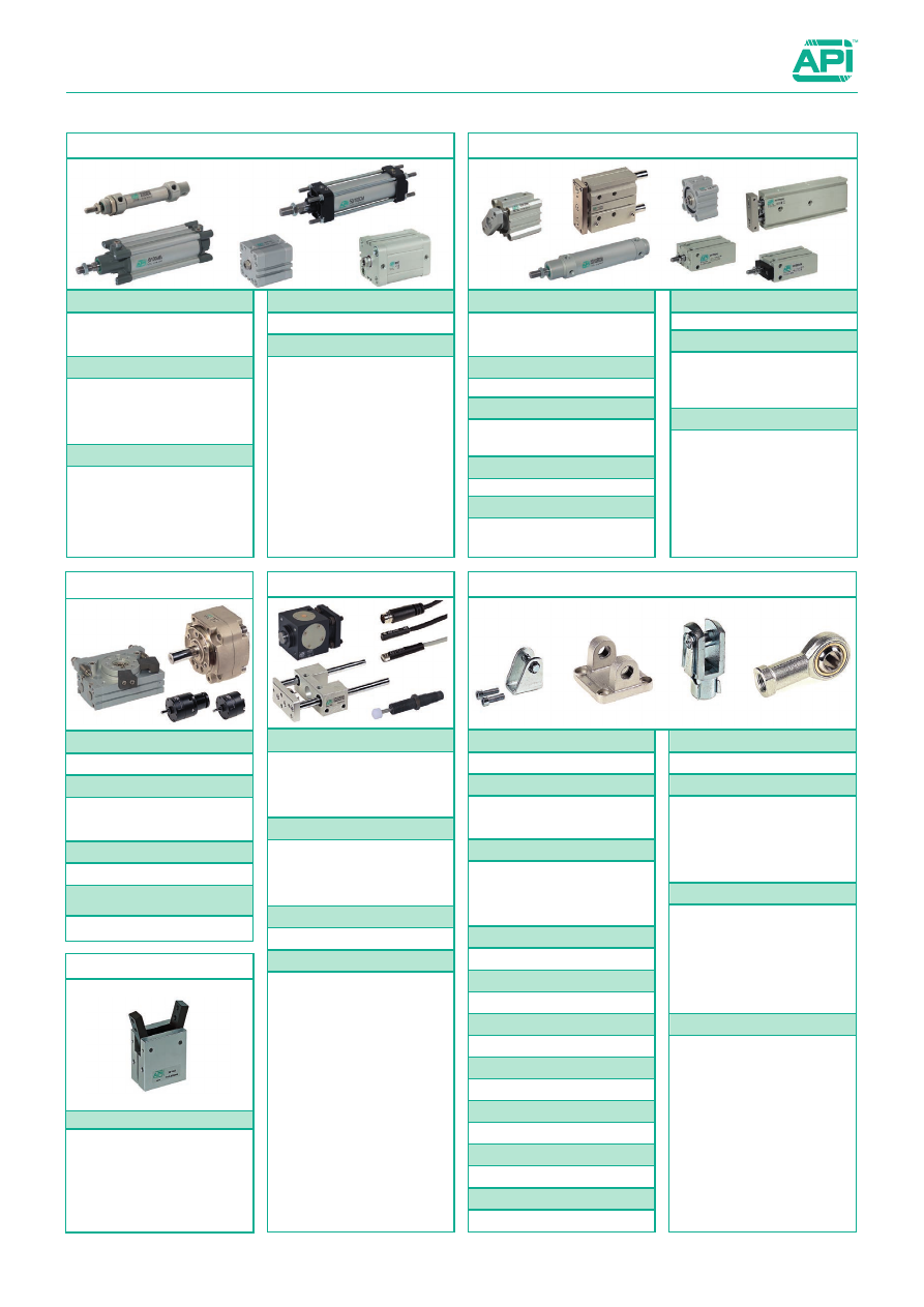
Cylinders and their accessories

Standard Range

Mountings

ISO 6432 mountings

CF - P - F

1.95.1

ISO 15552 mountings (Alluminium)

CF - CM - CFS - ASV - P 

CMS -AS

1.97.1

ISO 15552 mountings (Steel)

CF - CM - ASV - SEC - CFS - CMS

ASS - FL - FLV - PB - CT - CTS - ST

CFA - CTA

1.98.1

CNOMO mountings (Alluminium)

CF - AN - AS - P - PL

1.99.1

CNOMO mountings (Steel)

FL - PB - SEC - CT - CTS

1.99.50

UNITOP mountings (Alluminium)

CM - CF - FL

1.100.1

UNITOP mountings (Steel)

CM - CF - FL - PB

1.100.50

Round cylinders mountings

CF - P - CP - GH - SEC

1.96.1

Short stroke cylinders mounting

CM - N - P

1.20.20

Short stroke cylinders mounting

P - SI - CL - C

1.26.28

Hand grips mountings

PM - FP

1.80.60

Piston rod accessories - Clevis

FF ISO

1.85.1

FF DIN

1.85.5

FF CNOMO

1.85.10

FE

1.85.20

Piston rod accessories - Rod ends

RF - RM  ISO8139

1.90.1

GB

1.90.10

RBI

1.90.20

RBL

1.90.30

GC

1.90.40

Mounting screws and nuts

SCREW - NUT - GROWER

1.101.1

ISO 21287

CIS - CI - CIN

1.16.1

UNITOP

CS

1.17.1

CD-CDN

1.17.10

Cylinders to standard

ISO 6432

MS - MSM

1.2.1

MD - MDM - MDMA

1.2.10

ISO 15552

AMA - AMT (32÷125)

1.5.1

BMA - BMT (32÷125)

1.5.100

AMT (160÷320)

1.8.1

CNOMO 06.07.00

CX - CM

1.14.1

Round

RS - RD - RDM - RDMA

1.11.1

RED - REDM

1.11.10

Compact

DU - DUM - DUN - DUNM

1.18.1

Short stroke

BS - BSM

1.20.1

BD - BDM - BDMN

1.20.10

Compact guided

GEDB - GEDS

1.23.1

Compact guided and stopper 

GPB - GPS

1.23.50

Twin-rod cylinders

GSB - GSS

1.24.1

Rodless cylinders

S1 - S2

1.26.1

S3 - S5 - S6

1.26.10

S4

1.26.20

Cartridge

MCN - MCF

1.55.1

Cylinders not to standard

Slide units

UGLB - UGPB - UGPS (12÷25)

1.70.1

UGLB - UGPB - UGPS (32÷100)

1.70.20

SCSG

1.70.40

Blocking piston rod units

ABS...CRD - ABS...ARD (20÷25)

1.75.1

ABS...CRD - ABS...ARD (32÷125)  1.75.10

ABK...

1.75.30

Shock decelerators

DR - DRF

1.105.1

Sensors and brackets

ASV...

1.110.1

ASC...

1.110.2

CAV...

1.110.3

MK500A  -  MK502A

1.110.10

ASH...

1.110.20

AFM - AFR - AS...

1.120.1

Cylinders accessories

Rotary actuators

Rotary cylinders

CRTH - CRTHD - CRTF

1.40.1

Hi-rotors

ARTM... (4÷10)

1.50.1

ARTM... (12÷25)

1.50.10

Rotary actuators double rack

ARC

1.50.20

Rotary actuators with pignon and 
external mechanical stopper

ARP

1.50.30

Hand grips

Grips

PAB

1.80.1

PAC

1.80.11

PPB

1.80.20

PPC

1.80.30

PPD

1.80.40

PPE

1.80.50

3

PART 2 

 Valves

ISO 5599/1

ISO 1 Solenoid

ISO1E - ISO1K 

2.110.1

ISO1EL - ISO1KL

2.111.1

ISO 1 Pneumatic

ISO1P

2.113.1

ISO 1 Sub-bases

SBA1

2.120.1

ISO 2 Selenoid

ISO2E - ISO2K

2.130.1

ISO 2 Pneumatic

ISO2P

2.133.1

ISO 2 Sub-bases

SBA2

2.137.1

NAMUR

A1NE

2.88.1

A1NP

2.88.10

A1NE..Ex nA

2.88.20

A1NE..Ex ia

2.88.40

A1NE..Ex dm

2.88.60

A1NE..Ex db

2.88.80

A1NE..Ex mb

2.88.100

Control valves to standard

Slide valves

V26

2.300.1

Mini ball valves

MVS

2.310.1

Cast mini ball valves

MS

2.330.1

Ball valves

VSLO

2.340.1

Quick exhaust valves

VSR

2.360.1

Unidirectional valves

FF

2.370.1

Safety valves

VS - VSCC

2.390.1

Ancillary valves

Standard Range

Manual and mechanical valves

Control valves not to standard

Sottobasi 

A2B

2.105.4

Accessories

A2I - A2E - A2PC

2.105.5

A2T - A2S

2.105.6

SD25-5 - SD25-7 - SD25-10

2.105.7

Coding and code

2.105.8

Electric scheme

2.105.9

Solenoid valves for water and steam

AEN - AEV - AEP

2.165.1

Integrated circuits

AEF - APF - AEC - APC

2.170.1

Directly operated solenoid valves 

15 e 22 mm

AE05 15 mm

2.2.1

A1EM 22 mm

2.3.1

A1EMD 22 mm

2.3.10

Series A1 (1/8” - 1/4” - 1/2”)

Solenoid 1/8” 

A1E1

2.50.1 / 2.53.1

Pneumatic 1/8”

A1P1

2.56.1 / 2.59.1

Sub-bases 1/8”

A1B - A1C - A1T

2.65.1

Solenoid 1/4”

A1E2

2.70.1 / 2.73.1

Pneumatic 1/4”

A1P2

2.76.1 / 2.79.1

Sub-bases 1/4”

A1B - A1C - A1T

2.85.1

Solenoid 1/2”

A1E4 - A1K4

2.90.1 / 2.93.1

Pneumatic 1/2”

A1P4

2.96.1 / 2.99.1

Series A2  (1/4”)

Solenoid12 / 24 Volts

A2

2.105.1 

Ball valves with actuator

Limit switch box

SB200 - SB500 - SB700 

2.431.30

Handweel manipulator

GDB 

2.432.1

Actuators

Single acting

AR...SE

2.430.1

Double acting

AR...DE

2.430.10

Ball valves with actuators

Brass single acting

VSO...SE

2.431.1

Brass double acting

VSO...DE

2.431.10

Stainless Steel single acting

VSI...SE

2.431.10

Stainless Steel double acting

VSI...DE

2.431.11

Coils and connectors

Coils

ASA12 - ASA 2

2.200.1

ASA33 - ASA32

2.200.10

ASA34

2.200.30

ASA12/ATEX - ASA2/ATEX

2.200.50

ASA4/ATEX

2.200.51

Connectors

A192

2.210.10

A122

2.210.20

A182

2.210.30

A122/ATEX - A182/ATEX

2.210.50

Manual series A1 (1/8” - 1/4”)

A1MA1 (1/8”)

2.230.1 / 2.235.1

A1MA2 (1/4”)

2.236.1 / 2.239.1

Foot

AVP

 2.250.10

Mechanical

Microvalves

AM

2.255.1 / 2.260.1

AP

2.265.1

AC

2.270.1

Valves 1/8”

AC

2.275.1

A1ME...ANT

2.280.1

A1ME...RLB

2.290.1

A1ME...RLBR

2.290.1

Plates

PSN

2.88.210

PN

2.88.210

PSV

2.220.1

Speed controllers

APNRDA

2.88.200

APNRSN

2.88.200

Accessories for valves

PART 3


Airline equipment and pressure-gauges

PART 4

 Accessories

Size  1/4”

A14FRRL - A14FRR

A14F - A14R - A14L

3.2.1

Size  3/8”

A38FRRL - A38FRR

A38F - A38R - A38L

3.2.10

Size 1/2

A12FRRL - A12FRR

A12F - A12R - A12L

3.2.20

Size 1”

A01FRRL - A01FRR

A01F - A01R - A01L

3.2.30

Modular air-line equipment

Push-in fittings

R

4.2.1

RHP

4.3.1

RT

4.5.1

Rapid fittings

C

4.20.1

Compression fittings

O

4.25.1

Standard fittings

A

4.35.1

Quick-lock couplings

20

4.45.1

21

4.45.11

26

4.45.21

Fittings and quick-lock couplings

Standard Range

4

Multiple connectors

A013P - A113P - A213P

4.55.1

Collectors

RX - RY - RZ - RR

4.60.1

Tubes and spirales

TR - TPU - TP - TN

SR - SPU 

4.65.1

FS - FW - CP - CPFW

4.65.11

Tube cutters

PTP - PTM - LPTP

LPTM - TSC

4.65.21

Blow guns

AH - AN - AM 

AR - AT - VR - SD

4.65.31

Washers

RA - RN - RR - RF - RB

4.65.41

Accessories

Air reservoirs

SBCV

4.70.1

Accessories

STSB - PRSB - VCSB

4.70.11

Air reservoirs and accessories

In line

V52 - V53 - V54 - V55

4.80.1

For cylinders

V15 - V14 - V17 - V40 

V18 - V41 - V20 - V39 

V37 - V38 - V36 - V50 

4.80.11

Silenced for valves

AVE - AVS - AVT 

AVL - AVC - AR07

4.80.50

ASN - ASP - ASPM 

ASE - AR

4.80.81

Flow regulators

AC400

3.10.1

AC700

3.10.1

Microregulators

ASA.. - TM..F

TM - L - DT..

DSL - SL - DST

ST - SR - SFL

D - VMS - TP..F

TP..L - CA../25

CA../5 - DF

OL - ORT

3.5.1

Mounting accessories and spare parts

Analog Pressure and vacuum gauges

M - MR - MF - MP

3.50.1

Digital Pressure and vacuum gauges

AKP60...

3.60.1

Pressure and vacuum gauges

AVP

3.3.1

Modular soft-start valve

Digital Pressure Switch

AKP43...

3.70.1

Pressure switch

continued 

PART 4

 Accessories

PART 5


Stainless steel components

Standard Range

5

Slow starter

V61

4.83.66

Threshold sensor

V62

4.83.71

In line pressure gauges

V51

4.83.23

Adjustable pressure switches

PR

4.83.31

Stop valves

V45

4.83.41

Throttle fitting

V44

4.83.56

Pneumatic switch

V46

4.83.61

V48

4.83.62

Fittings with non return valve

V56

4.83.1

Stop fittings

V59

4.83.5

Circuit selectors

V60

4.83.11

Pressure regulators

V57 - V58

4.83.21

V47

4.83.25

Accessories with integrated function

Plastic polymer silencers

SPD - SPF - SPS

AS19 - AS22

4.85.1

Sintered silencers

AC - ACQ - AE - AEA AEB 
ACT - AEP - AFE - AP
AT - ATT - ACI

4.85.11

Metallic silencers

M - MI

4.85.21

Exhaust conveyors

CSC1

4.90.1

Silencers

ISO 6432 cylinders

MDMX - MDMAX

5.1.1

ISO 15552 cylinders

AMX

5.5.1

Round Cylinders

RXD

5.11.1

RDX

5.11.10

ISO 21287 cylinders

CIX - CIXN - CIXS

5.16.1

Piston rod clevis

FFXISO - FFXDIN

5.20.1

Piston rod ends

RFX...SE

5.25.1

GBX

5.25.10

GCX

5.26.1

ISO 6432 mountings 

CFX - PX - FX

5.30.1

Mountings for round cylinders

CFX - PX - GHX - SECX

5.35.1

ISO 15552 mountings 

CFX - CMX - ASVX

SECX - CFSX - CMSX 

ASSX - SECX -...ARAQ

FLVX - PBX - CTX

5.40.1

Mounting screw 

VTCEIX - VBTRX - GRAINS

5.50.1

Cylinders and mounting 
accessories

Stainless steel NAMUR
solenoid valves

Air reservoires

SBCX

5.180.1

Accessories

STSBX - AX0061212

5.180.5

Flow regulators

VX52 - VX53

VX15 - VX18

5.185.1

Silencer and exhaust 
silenced regulators

AFEX - AEX

AVRX - AEPX

5.190.1

Accessories 

Size 1/4”

A14FRRLX - A14FRRX

A14FX - A14RX - A14LX

5.140.20

Size 1/2

A12FRRLX - A12FRRX

A12FX - A12RX - A12LX

5.140.40

Size 1”

A01FRRLX - A01FRRX

A01FX - A01RX - A01LX

5.140.60

 Modular air-line equipment

Mini ball valves

MVSX

5.100.1

Ball valves

VSLX

5.101.1

Unidirectional valves

FFX

5.105.1

Quick exhaust valves

VSRX

5.110.1

Ancillary valves

Push-in fittings

RX

5.150.1

Rapid fittings

CX

5.155.1

Compression fittings

OX

5.160.1

Standard fittings

AX

5.165.1

Quick-lock couplings

GXA

5.170.1

GXF

5.172.1

Swivel joints

GGLX - GGAX

5.175.1

Fittings and quick-lock couplings 

Series AX

AX1E

5.70.1

AX1P

5.76.1 

AX1NE

5.80.1 

AX1..Ex nA

5.81.1 

AX1..Ex ia

5.82.1

AX1..Ex dm

5.83.1 

AX1..Ex d

5.84.1 

AX1..Ex mb

5.85.1 

6

Special executions and complete systems

Special applications

As a natural consequence of competition in recent years it has been necessary for manufacturers to fulfil 
customers requirements with special custom made products.
A.P.I. S.r.l., whose aim is to satisfy its customers and to improve its way of working, decided to pursue 
this and to consider these special products as its strength from researching to machining, from mounting 
to testing.

Complete systems

In order to achieve the aims mentioned above, A.P.I. S.r.l. are now in a position to manufacture complete 
systems, such as control panels, to satisfy customer requirements, enabling the customer to achieve their 
objectives.

Menbrane brake  ►

cylinder

Customized  ►

guided cylinder

◄   Customized


guided cylinder

◄   Customized


stainless steel 
cylinder

◄   Customized


cylinder

Customized  ►

gripper

Cylinder with  ►

adjustable

stroke

◄   Filler

◄   Cylinder with


micro-metric 
double stroke 
regulation

◄   Knifeholders

ATEX

Group I

(Mining)

Group II

(Industrial)

Category M

Category 1

Category 2

Category 3

1

2

G

(Gas)

(Zone 0)

D

(Polveri)

(Zone 20)

G

(Gas)

(Zone 1)

D

(Polveri)

(Zone 21)

G

(Gas)

(Zone 2)

D

(Polveri)

(Zone 22)

Equipment 
that 
guarantees 
a very high 
safety level. 
Guaranteed 
operations 
in case of 
possible 
mistakes

Equipment 
that 
guarantees 
a very high 
safety level. 
Possible 
interruption 
in case of 
potential 
explosive 
atmosphere 
condition.

Equipment that guarantees a 
very high safety level. 

In case  potential explosive 
atmospheres should occur 
frequently and for long 
periods.

Equipment that guarantees a 
high safety level. 

In case potential explosive 
atmospheres should occur 
occasionally.

Equipment that guarantees a 
standard safety level. 

In case potential explosive 
atmospheres should occur 
only rarely and for short 
period.

7

Directive 2014/34/UE was made by the European Union to regulate the market of products used in potentially explosive atmo-
sphere, classifying technical characteristic and regulations. 
Directive 2014/34/UE entered into force on 30 March 2014 and cancelled Directive 94/9/CE starting from 20 April 2016; this 
impose ATEX certification to all the products sold in the European Community if installed in potentially explosive environments, 
independently from the production seat and from the norms in force. 

Ex. Not electrical equipment (UNI EN 13463)

Class of temperature

Max. external

temperature (°C)

T1

450

T2

300

T3

200

T4

135

T5

100

T6

85

Standard products certified ATEX

Directive 2014/34/EU

II 2Gc IIC T5
II 2Dc T100°C

Group I:

 equipment suitable to be used under-

ground in the mining sites and in their surface 
plant.  
(Category M1 and M2)

Group II:

 equipment suitable to be used 

in  other  sites  which  could  be  potentially         
explosive. 
(Category 1, 2, 3)

The products classified in the two groups can 
have different protection ways against the 
explosion, according to the zone where the 
equipment is installed.

The cover of the equipment has not to have on the surface some flammable 
points where spontaneous combustion can occur.
Different  substances  can  flame  at  different  temperatures.  Less  is  the                        
flammable temperature, higher is the substance  dangerous. For this reason 
each equipment, used in an  explosive environment, is classified according to 
the maximum surface temperature it generates.
The maximum surface temperature must be always lower than the spontaneous 
combustion temperature of powder and gas.

Temperature classification for gas and dust

Gas groups

Explosive gas

Group IIA

Propane

Group IIB

Ethylene

Group IIC

Hydrogen / Acetylene

ATEX directive shows a classifications of gas and dust which could be potential-
ly explosive against the ones the user can protect himself by using the correct 
product with suitable protection system. 

With reference to the products of group II, the dangerous of gas and dust 


covered by the products increase in  IIA a and IIIA category the less dangerous 
to IIC and IIC the most dangerous.

To determinate the gas and the dust potentially present and the relative  sharing, 
please check the table for group II.

Gas and dust group

Classifications of the groups in categories

ATEX product labelling

Ex. Electrical equipment (CEI EN 60079)

II 2G Ex db mb IIC T5 Gb
II 2D Ex tb IIIC T95°C IP66 Db

CE mark

Conformity comunitary mark to the safety requirements

Specific mark for explosion protection

Gas

ATEX mark

II

Equipment group

2G

Equipment category

Type of protection

Ex

Explosion protected equipment

db

Type of protection from exolosive ignition (may be multiples)

mb

Type of protection from exolosive ignition

IIC

Gas group

T5

Class of temperature

ELP

Gb

Equipment protection level

Dust

ATEX mark

II

Equipment group

2D

Equipment category

Type of protection

Ex

Explosion protected equipment

tb

Type of protection from exolosive ignition

IIIC

Dust group

T95°C

Max. external temperature

IP66

Degrees of protection (CEI EN 60529)

ELP

Db

Equipment protection level

CE mark

Conformity comunitary mark to the safety requirements

Specific mark for explosion protection

Gas

ATEX mark

II

Equipment group

2G

Equipment category

Type of

protection

c

Type of protection from exolosive ignition

IIC

Gas group

T5

Class of temperature

Dust

ATEX mark

II

Equipment group

2D

Equipment category

Type of


protection

c

Type of protection from exolosive ignition

T100°C

Max. external temperature

Dust groups

Explosive dust

Group IIIA

Fibers

Group IIIB

Not combustible dust

Group IIIC

Combustible dust

8

Valves, solenoid valves and relevant sub-bases

Solenoid valves

Series A1, 1/8”

2.3.10 - 2.50.1 - 2.53.1

Series A1, 1/4”

2.3.10 - 2.70.1 - 2.73.1

Series AX1, 1/4”

5.70.1 - 5.73.1

Series A1, 1/2”

2.90.1 - 2.96.1

Pneumatically operated valves

Series A1, 1/8”

2.56.1 - 2.59.1

Series A1, 1/4”

2.76.1 - 2.79.1

Series AX1, 1/4”

5.76.1 - 5.79.1

Sub-bases

Series A1, 1/8”

2.65.1

Series A1, 1/4”

2.85.1

NAMUR solenoid valves

Series A1, 1/4”

2.88.1 - 2.88.4

Series AX1, 1/4”

5.80.1

API & ATEX

Pneumatic cylinders, slide units and mounting accessories

ISO 6432 cylinders

MS - MSM

1.2.1

MD - MDM - MDMA

1.2.10

Stainless steel ISO 6432 cylinders

MDMX - MDMAX

5.1.1

ISO 15552 cylinders

AMAK - AMTK

1.5.1 - 1.8.1

Stainless steel ISO 15552 cylinders

AMX

5.5.1

Round cylinders

REDK -  REDMK

1.11.1

Stainless steel round cylinders

RXD

5.11.1

CNOMO cylinders

CXK - CMK

1.14.1

Compact cylinders ISO 21287

CIS (Ø 16 ÷ 25) - CISK (Ø 32 ÷ 125)

1.16.1

CI (Ø 16 ÷ 25) - CIK (Ø 32 ÷ 125)

1.16.1

Stainless steel Compact cylinders ISO 21287

CIX (Ø 16 ÷ 25)

1.16.1

Compact cylinders UNITOP

CS

1.17.1

CD

1.17.10

Short stroke cylinders

BS - BSM

1.20.1

BD - BDM - BDMN

1.20.10

Compact guided cylinders

GEDB - GEDS

1.23.1

Slide units

UGLBK - UGPBK - UGPSK

1.70.1 - 1.70.20

Mounting accessories

Clevis

1.85.1 - 5.20.1

Bearings

1.90.1 - 5.25.1

Articulated couplings

1.90.40 - 5.26.1

Mountings

1.95.1 - 5.30.1

Brackets for switches

1.120.1

Marked in accordance to 2014/34/EU

II 2Gc IIC T5 
II 2Dc T100°C

Marked in accordance to 2014/34/EU

II 2Gc IIB/IIC T5 
II 2Dc T100°C

Valves ISO 5599/1

ISO1

2.110.1 - 2.120.1

ISO2

2.130.1 - 2.137.1

Integrated circuits

Flip-flop 1/4”

2.110.1 - 2.120.1

Manually operated valves

Series A1, 1/8”

2.230.1 - 2.233.1

Series A1, 1/4”

2.236.1 - 2.239.1

Standard products certified ATEX

Directive 2014/34/EU

9

Valves, solenoid valves and relevant sub-bases

Stainless steel airline equipment

Stainless steel airline equipment

Series 1/4”

5.140.20

Series 1/2”

5.140.40

Series 1”

5.140.60

API & ATEX

Switches

Switches

MK500A

1.110.10

Switches

MK502A

1.110.10

Coils

ASA12/ATEX

2.200.50

Coils

ASA2/ATEX

2.200.50

Connectors

A18209N/ATEX 

2.210.50

Marked in accordance to 2014/34/EU

II 3G Ex nA IIC T5 Gc X
II 3D Ex tc IIIC T95°C Dc X

Marked in accordance to 2014/34/EU

II 2G Ex mb IIC T5 Gb
II 2D Ex tb IIIC T95°C IP66 Db

Marked in accordance to 2014/34/EU

II GD

For switches MK500A

II 3D Ex tc IIIC  T125°  Dc  X

For switches MK502A

II 1G Ex ia IIC T4 Ga
II 1D Ex ia IIIC T135° Da

Standard products certified ATEX

Directive 2014/34/EU

Air-reservoirs

Air-reservoirs

SBCV

4.70.1

SBCX

5.180.1

Marked in accordance to 2014/34/EU

II 2GDc IIC TX

Marked in accordance to 2014/34/EU

II 2Gc IIC TX
II 2Dc IIIC TX

Connectors

A12209N/ATEX

2.210.50

Marked in accordance to 2014/34/EU

II 2G IIC T6 Gb
II 2D Ex tb IIIC T85°C IP65/IP67

General technical information

PHYSICAL MAGNITUDES AND DATA

The pneumatic components use compressed air. Pressure is a force that is applied per unit of area. The pressure that can be measured with the 
special instrument - the manometer - is called manometric or relative to the atmospheric pressure in which the instrument is emerged. Absolute 
pressure is obtained by adding atmospheric pressure to the manometric pressure. 

UNITS OF MEASUREMENT - INTERNATIONAL SYSTEM  (SI)

The SI units have been introduced in the majority of countries on the basis of international conventions.
The aim is to achieve sole 

UNITS OF MEASUREMENT

 in order to avoid the difficult conversions from one system of measurement to another. 

The 

SI SYSTEM

 considers seven fundamental physical magnitudes with their respective units of measurement. All the other units of 

measurement are derived from these. 
The fundamental units are:
Length in metres [ m ], mass in kilograms [ Kg ], time in seconds [ s ], electrical current in amperes [ A ], temperature in degrees Kelvin [ °K ], 
molecular quantity in moles [ mol ], luminous intensity in candelas [ cd ]. 
Forces are derived magnitudes and are expressed in Newtons [ N ]. 
According to the fundamental law of dynamics, one Newton is the force required to accelerate a mass of 1 Kg 
1 m/s

2

.

As 1 Kp is the force required to give a mass of 1 Kg the acceleration of gravity, which is equivalent to 9.81 m/s

2

, it follows that 1 Kp = 9.81 

N = approx. 10 N. Indeed, the latter value is assumed in order to avoid an excessive precision of calculation.  
Pressure is thus measured in N/m

2

, a unit known as the Pascal [ Pa ]. The unit of measurement that is equivalent to 100x103 Pa [ bar ] is still 

accepted. We can write 1 bar = 100 KPa.

12

SI UNIT

Magnitude

Symbol of 
formula

SI Unit

Accepted units of measurement

Conversion factors

Name

Unit

Multiple

Name

Unit

Lenght

I

Metre

m

km
cm
mm

Area

A

Square metre

m

2

cm

2

mm

2

Are
Hectare

a
ha

1 a = 10

2

 m

2


1 ha = 10

4

 m

2

used only 
for land

Volume

V

Cubic metre

m

3

cm

3

mm

3

Litre

l

1 l = dm

3

 = 0,001 m

3

Mass

m

Kilogrm

kg

Mg
g
mg

Ton

t

1 t = 1000 kg = 1 Mg

Time

t

Second

s

Minute 
Hour 
Day

min
h
d

1 min = 60 s
1 h = 60 min = 3600 s
1 d = 24 h = 86400 s

Number of revolutions

n

Revs 
per second

1/s
s

-1

Revs 
per second

1/min 
min

-1

1/min = 1/60 s

Velocity

v

Metre 
per second

m/s

Kilometre 
per hour

km/h

1 km/h =  


m/s

Flow

V

Cubic metre 
per second

m

3

/s

m

3

/h

l/min
l/s

1 m

3

/h = 16,67 l/min = 0,28 l/s

1 m

3

/s = 60.000 l/min

Force

F

Newton

N

1 N = 1 kg m/s

2

1 kp = 9,81 N = 10 N
1 kp = 1 da N

Pressure

P

Newton per 
square metre 
pascal

N/m

2

Pa

Bar

bar

1 N/m

2

 = 1 Pa

1 bar = 10

5

 Pa

Energy
work
Quantity of calories

W

Joule

J

Kilowatt-hour

kWh

1 J = 1 Nm = 1 Ws = 1 kg m

2

/s

2

1 kWh = 3,6 Mj

Momento of force, torque

M

Newton-metre Nm

1 kpm = 9,81 Nm

Power
Energy absorption
Heat absorption

P

Watt

W

1 W = 1 J/s = 1 Nm/s
1 kpm/s = 9,81 W

Dynamic viscosity

h (m)

Pascal-second Pas

1 Pas = 1 Ns/m2 = 1000 mPas
1 cp = 1 mPas

Kinetic viscosity

u

Square metre 
per second

m

2

/s

1 cST = 10-

6

 m

2

/s

1 cSt = 1 mm

2

/s

Temperature

Kelvin

k

Degree 
Centigrade

°C

Frequency

f

Hertz

Hz

1

3,6

General technical information

VOLUME IN NORMAL CONDITIONS

The following are considered normal conditions of the fluid: temperature °K = 273 + 20 °C, pressure = 1 bar.
For the following considerations, the equation of state of perfect gases is also accepted as valid for the actual air gas.
This is: PV = nRT   where    

P = absolute pressure of the gas [ bar ]


V = volume [ m

3

 ]


T = absolute temperature [°K ]

Imagine that we wish to bring a given volume of air V1, subject to pressure P1 and temperature T1 back to the normal conditions P0, V0, T0.
We can say that the situation will pass from P1V1 = nRT1 to P0V0 = nRT0.
Therefore, P1V1/T1 = P0V0/T0, from which it follows that:
V0 = V1x(P1/P0)x(T0/T1).
In normal conditions volume is directly proportional to the relationship of the pressure values and inversely to that of the temperature values. 
As the latter are expressed as 273 + °C, the influence of their relationship is negligible, consequently we normally consider:
V0 = (P1/P0)x V1 [ Nm

3

 ].

Table of symbol

13

COMPRESSOR

VACUUM PUMP

PNEUMATIC MOTOR WITH ONE
DIRECTION OF ROTATION

PNEUMATIC MOTOR WITH TWO
DIRECTION OF ROTATION

PNEUMATIC MOTOR WITH ONE
DIRECTION OF ROTATION AND 
VARIABLE DISPLACEMENT VOLUME

PNEUMATIC MOTOR WITH 2
DIRECTION OF ROTATION AND 
VARIABLE DISPLACEMENT VOLUME

ROTARY CYLINDER

SINGLE ACTING CYLINDER WITH RETURN 
STROKE BY  NON-DEFINED STROKE

SINGLE ACTING WITH RETURN STROKE BY 
SPRING

DOUBLE ACTING CYLINDER

DOUBLE ACTING CYLINDER WITH 
PERMANENT MAGNET

DOUBLE ACTING CYLINDER WITH 
CUSHIONINGS NON-ADJUSTABLE AT BOTH 
ENDS

DOUBLE ACTING CYLINDER WITH 
CUSHIONINGS ADJUSTABLE AT BOTH ENDS

SINGLE ACTING TELESCOPIC 
CYLINDER

DOUBLE ACTING TELESCOPIC 
CYLINDER

DOUBLE ACTING CYLINDER WITH THROUGH 
ROD

DOUBLE ACTING CYLINDER WITHOUT 
MAGNETIC COUPLING ROD (PISTON - 
MOBILE EQUIPMENT)

CONDITIONING UNIT F.R.L 
(FILTER, REGULATOR, LUBRICATOR)

FILTER

MANUALLY OPERATED WATER 
SEPARATOR

WATER SEPARATOR WITH AUTOMATIC 
DRAINING

FILTER WITH WATER SEPARATOR (WITH 
AUTOMATIC DRAINING)

AIR DRIER

LUBRICATOR

General technical information

Table of symbol

14

COOLER (WITH REPRESENTATION OF THE 
COOLING PIPES)

VESSEL (AIR-RESERVOIR)

SILENCER

PRESSURE SOURCE

EXHAUST

PRESSURE GAUGE

VISUAL DISPLAY

2/2-WAY VALVE N.C. 
(2 CLOSED PORTS, CLOSED POSITION IN 
NEUTRAL POSITION)

2/2-WAY VALVE
N.O. (ONE FLOW PATH, FLOW IN 
NEUTRAL POSITION)

3/2-WAY VALVE
N.C. (IN 1ST SWITCH POSITION INLET IS 
CLOSED)

1 (P) 3 (R)

2 (A)

3/2-WAY VALVE N.O. (IN THE 2ND POSITION 
AIR IS EXHAUSTED OR THE RETURN FLOW 
LINE IS CLOSED)

4/2-WAY VALVE (WITH 2 OPEN POSITIONS 
AND ONE EXHAUST)

5/2-WAY VALVE (WITH 2 OPEN POSITIONS 
AND 2 EXHAUSTS)

3/3-WAY VALVE WITH CLOSED NEUTRAL 
POSITION AND 2 OPEN POSITIONS

4/3-WAY VALVE WITH CLOSED NEUTRAL 
POSITION AND 2 OPEN POSITIONS

4/3-WAY VALVE WITH FLOATING
NEUTRAL POSITION AND 2 OPEN 
POSITIONS

5/3-WAY VALVE WITH CLOSED 
NEUTRAL POSITION AND 2 OPEN 
POSITIONS

5/3-WAY VALVE WITH FLOATING
NEUTRAL POSITION AND 2 OPEN 
POSITIONS

GENERAL MANUAL OPERATION (WITHOUT 
SPECIFYING TYPE OF 
CONTROL)

MANUAL OPERATION BY PUSHBUTTON

MANUAL OPERATION BY PUSHBUTTON WITH 
MECHANICAL GRIP

MANUAL OPERATION BY LEVER

MANUAL OPERATION BY PEDAL

MECHANICAL OPERATION BY STEM 
OR KEY

MECHANICAL OPERATION BY SPRING

MECHANICAL OPERATION BY ROLLER

MECHANICAL OPERATION BY ROLLER 
OPERATING IN ONE DIRECTION ONLY (IDLE 
RETURN)

PNEUMATIC OPERATION WITH DIRECT 
ACTION BY APPLICATION OF PRESSURE

PNEUMATIC OPERATION BY PRESSURE 
RELIEF

PNEUMATIC OPERATION BY DIFFERENT 
CONTROL SURFACES. IN THE SYMBOL THE 
LARGER RECTANGLE REPRESENTS THE 
LARGER CONTROL SURFACE

PNEUMATIC OPERATION BY 
APPLICATION OF PRESSURE TO 
THE PILOT VALVE

ELECTRICAL OPERATION BY 
SOLENOID WITH ONE WINDING

COMBINED OPERATION BY SOLENOID AND 
PILOT VALVE

COMBINED OPERATION: BY SOLENOID AND 
PILOT VALVE AND GENERAL MANUAL

General technical information

Table of symbol

15

GENERICALLY ELECTRICAL AND MANUAL 
OPERATION AND EXTERNAL AIR PILOT AT 
BOTH ENDS: TWO STABLE POSITION

GENERICALLY ELECTRIC AND MANUAL 
OPERATION AND EXTERNAL AIR PILOT FOR 
3 POSITION VALVE

SHUTTLE VALVE (OR TYPE)

TWO PRESSURE VALVE (AND TYPE)

QUICK-EXHAUST VALVE

NON-RETURN UNLOADED VALVE

NON-RETURN SPRING-LOADED VALVE

CONTROLLED NON-RETURN VALVE

FLOW RESTRICTOR WITH CONSTANT 
SECTION

DIAPHRAGM FLOW RESTRICTOR WITH 
CONSTANT SECTION

ADJUSTABLE FLOW CONTROL VALVE

FLOW CONTROL VALVE WITH
UNIDIRECTIONAL ADJUSTEMENT

CONNECTED QUICK-LOCK COUPLINGS 
WITHOUT MECHANICALLY OPENING 
NON-RETURN VALVE

CONNECTED QUICK-LOCK COUPLINGS WITH 
MECHANICALLY OPENING 
NON-RETURN VALVE

UNCOUPLED (WITH OPEN END) QUICK-LOCK 
COUPLINGS WITHOUT 
NON-RETURN VALVE

UNCOUPLED QUICK-LOCK COUPLINGS WITH 
END BLOCKED BY A NON-RETURN VALVE 
WITHOUT SPRING

REGULATOR WITHOUT EXHAUST

REGULATOR WITH EXHAUST

SEQUENCE VALVE (PRIORITY VALVE)

SHUT OFF VALVE

VACUUM GENERATOR (FOR VENTURI 
EFFECT)

PNEUMATIC PRE-DETERMINING 
COUNTER

PNEUMATIC TIMER WITH DELAYED 
ENERGISING, WITH VALVE 3/2 N.C.

PNEUMATIC TIMER WITH DELAYED 
ENERGISING, WITH VALVE 3/2 N.O.

PNEUMATIC TIMER WITH DELAYED 
DE-ENERGISING, WITH VALVE 3/2 N.C.

PNEUMATIC TIMER WITH DELAYED DE-
ENERGISING, WITH VALVE 3/2 N.O.

PRESSURE SWITCH (ADJUSTABLE)

PNEUMATIC-ELECTRICAL CONVERTER

REFLEX SENSOR

BACK PRESSURE END STOP

AIR BARRIER SENDER (EMITTER)

AIR BARRIER RECEIVER

GAP SENSOR

MAGNETICALLY OPERATED 
PNEUMATIC REED SWITCH

17

Index

2

3

4

5

1

CYLINDERS 
AND THEIR 
ACCESSORIES

VALVES

AIRLINE EQUIPMENT
AND 
PRESSURE-GAUGES

ACCESSORIES

STAINLESS 
STEEL
COMPONENTS

Note

1

Cylinders and their accessories

1

1.0

Cylinders and their accessories

0

1

2

4

5

6

7

8

0

1

2

3

4

5

6

7

8

9

10

11

12

13

14

15

16

17

18

19

mm

in

mm

Technical data:

from page 1.1.1

ISO 6432

from page 1.2.1

CNOMO 

from page 1.14.1

Compact cylinders ISO 21287

from page 1.16.1

Compact cylinders

from page


1.18.1

Short stroke cylinders

from page


1.20.1

Round cylinders

from page 1.11.1

Rodless cylinders

from page


1.26.1

Rotary cylinders

from page


1.40.1

Hi-rotor cylinders

from page


1.50.1

Compact guided cylinders

from page


1.23.1

Guiding and stopper cylinders

from page


1.23.50

Twinrod Cylinders

from page


1.24.1

Slide units for cylinders 
ISO 6431 - 6432

from page


1.70.1

from page


1.55.1

Cartridge cylinders

Hand grips

from page


1.80.1

Mounting accessories for
cylinders ISO 6432

from page


1.95.1

Mounting accessories for
cylinders ISO 15552

from page


1.97.1

Mounting accessories for
cylinders CNOMO

from page


1.99.1

Piston rod accessories

from page


1.85.1

Shock absorbers

from page


1.105.1

Mounting accessories for
cylinders compact UNITOP

from page


1.100.1

ISO 15552 (Ø 32-125)

from page 1.5.1

ISO 15552 (Ø 160-320)

from page 1.8.1

Switches and brackets

from page


1.110.1

Rotary actuators ARC - ARP

from page


1.50.20

Piston rod brake for cylinders 
ISO 6432 - 15552

from page


1.75.1

Compact cylinders UNITOP 

from page 1.17.1

1.1.1

Cylinders

Technical data

The pneumatic cylinder is an engine that uses pneumatic energy, transforming it into mechanical work by means of rectilinear 
movement.
It is composed of a tube, closed at the ends by two heads, within which a piston moves, separating two chambers. The piston 
is equipped with a rod that, when exiting through one or both of the heads, permits the exploitation of the force developed 
by the cylinder. 
The characteristic parameters of a cylinder are:
Bore  

=  internal diameter of the tube [ mm ].

Stroke  

=  working movement to be performed [ mm ].

Diameter of piston rod  =  closely correlated to the bore [ mm ].
Number of actings  

=  number of strokes per cycle during which work is performed. These may be either one


  (single acting); or two (double acting).

Operating pressure [ 1 bar ].
Operating temperature [ °C ].
Translation velocity [m/s].
Number of adjustable end cushionings.
Kinetic energy absorbed by the cushionings [Nm].
Air consumption [ nl/min ].
Theoretical force Ft [ N ]

BORE Ø

A finite number of bores are available, all of which are standardized. The range goes from bores measuring just a few milli-
metres to those of 300 mm.

PRESSURE p

This value is not very variable, due to technical-economical reasons. It covers the range 5-7 bar. A system operating at 6 
bar is considered optimized.

PISTON ROD DIAMETER  d

This is standardized for all the bores available.

STROKE c

The most frequently requested strokes are available in our warehouse. Any technically compatible stroke can be supplied in 
a short time. It is advisable to choose easily available strokes that are greater than the operating strokes, halting the stoke 
at the desired value by means of external mechanical stops, in order to obtain mechanical precision and greater durability 
of the cylinder.

OPERATING TEMPERATURE

Ambient temperature must not be such as to make the cylinder assume values outside the temperature range for which it 
was constructed. It is possible to construct cylinders that are resistant to very low or very high temperatures, using special 
materials.
The catalogues always show the operating temperature range.
The cylinder can also reach high temperatures due to particular conditions of use: in general, when the friction between 
the tube and the mobile apparatus increases greatly (e.g. due to high speeds with insufficient lubrication, the exhaustion of 
assembly lubrication or excessive compression of the air). The seals of the cylinder are the most short-lived component and 
those that are most sensitive to temperature.

TRANSLATION VELOCITY  v

It is advisable to adjust the translation velocity by means of the air discharge.
The movement of the piston is fairly regular even with minimum velocities of 40 mm/s.
The maximum velocity acceptable without additional lubrication to assembly lubrication, is equivalent to 1000 mm/s. 
Velocities of 2 ÷ 3 m/s can be reached with appropriate lubrication.
For high velocities, as for high masses, the kinetic energy to be reabsorbed is excessive for the air cushionings. It is nec-
essary to use external hydraulic cushionings of an appropriate size.


Content      ..      1       2         ..


//////////////////////