Rexroth: Screw Assemblies. Catalog (R999001185/2020-03) - page 13

180
Screw Assemblies | Ball Screw Assemblies BASA
End Bearings
Lubrication of the end bearings
Bearings for Ball Screw Assemblies are lubricated with grease for a lifetime of reliable service. It should be noted, however, that grease
lubrication does not facilitate the dissipation of heat in the bearings. The bearing temperature should therefore not exceed 50 °C, particularly
in machine tool applications. At higher temperatures circulating oil lubrication must be set up. Angular-contact thrust ball bearings of series
LGF, LGN are lifetime-lubricated with KE2P-35 grease as per DIN 51825. For regreasing, the quantities stated in the table below can be
applied via the lube ports provided on the bearings. Where there are pairs of bearings, please note that each bearing must be individually
lubricated via the lube port. Each bearing must be lubricated with half the value shown in the table.The maximum interval can be assumed to
be 350 million revolutions, in which case the larger of the two quantities should be used. As a rule, the initial grease quantity will therefore
last for the entire service life of a Ball Screw Assembly.
Relubrication quantities for angular-contact thrust ball bearings
Abbreviation
Quantity (cm3)
Abbreviation
Quantity (cm3)
Abbreviation
Quantity (cm3)
1)
2)
1)
1)
LGN-B-0624
0.33
0.22
LGN-B-1034
0.33
0.22
LGN-B-1242
LGF-B-1255
0.43
0.33
LGN-B-1747
LGF-B-1762
0.54
0.43
LGN-B-2052
LGF-B-2068
0.87
0.54
LGN-B-2557
LGF-B-2575
1.09
0.65
LGN-C-2557
LGF-C-2575
2.17
1.3
LGN-B-3062
LGF-B-3080
1.09
0.65
LGN-C-3062
LGF-C-3080
2.17
1.3
LGN-B-3572
LGF-B-3590
1.74
0.98
LGN-A-4075
2.17
1.30
LGN-A-4090
LGF-B-40115
6.52
3.80
LGN-A-5090
2.72
1.63
LGN-A-50110
LGF-A-50140
9.78
5.98
1) Shortened lubricating interval max. 10 M revolutions
2) Where there are pairs of bearings, lubricate each bearing via the lube port.
Lubricate each bearing with half the value shown in the table.
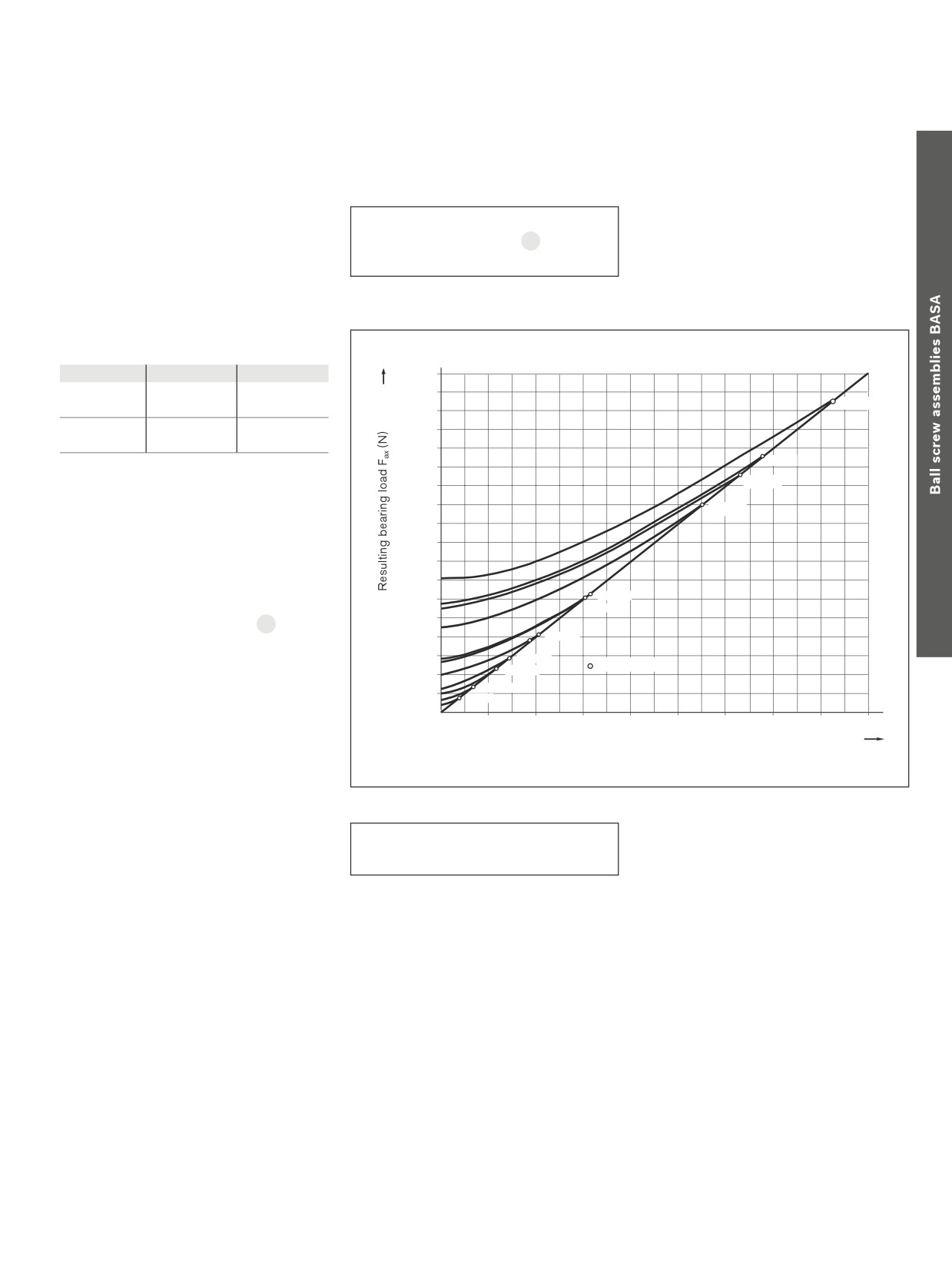
181
End Bearings
Calculation
Resulting and equivalent bearing
loads
For angular-contact thrust ball bearings
Fax
= resulting axial bearing load
(N)
LGN and LGF
Fcomb = X · Frad + Y · Fax
20
Fcomb = combined equivalent load
(N)
Angular-contact thrust ball bearings are
Frad
= radial bearing load
(N)
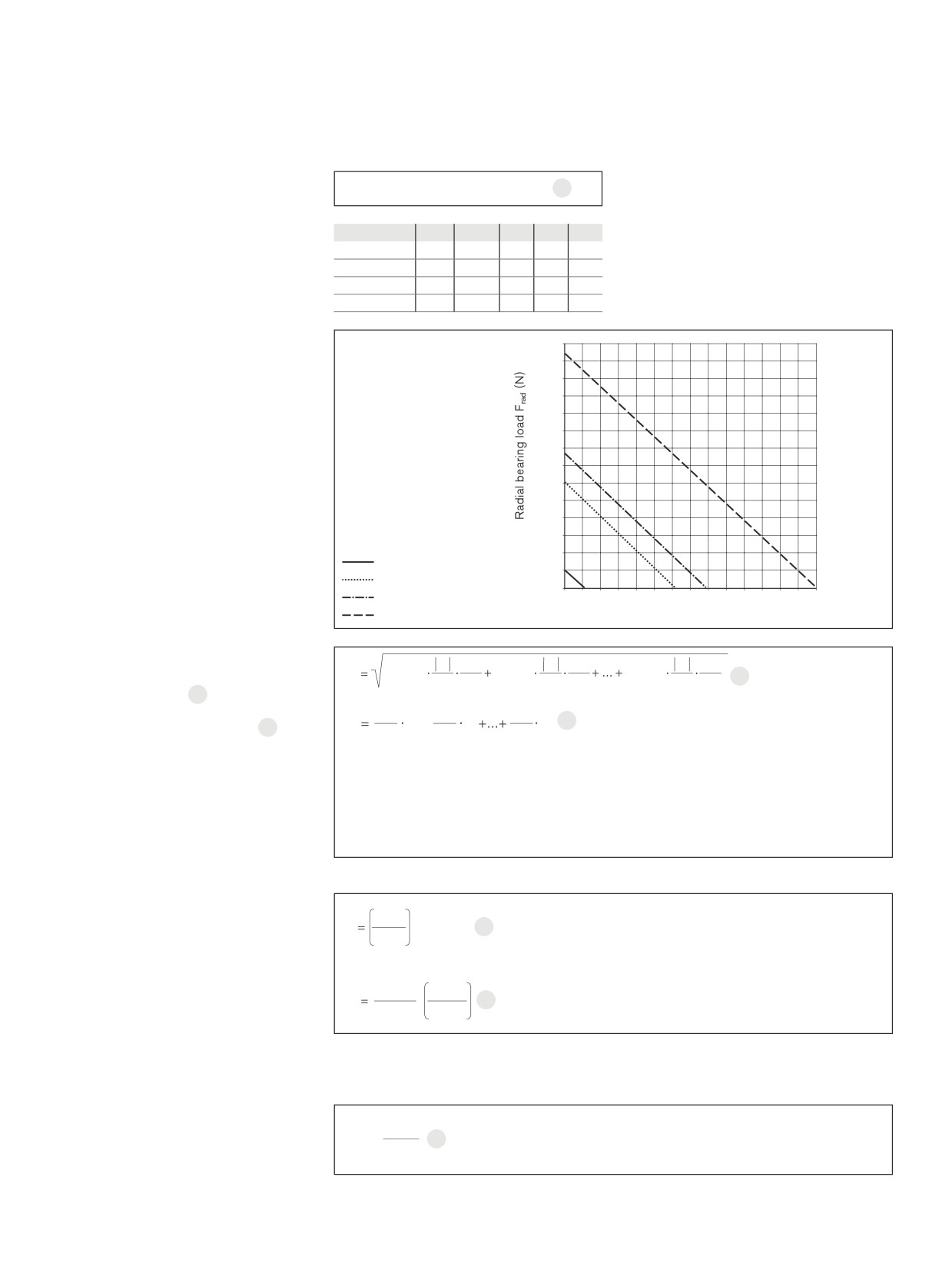
preloaded. The chart shows the result-
ing axial bearing load Fax as a function of
preload and axial operating load FLax.
For a purely axial load Fcomb = Fax.
Internal preload limit and resulting bearing load
α = 60°
X
Y
18000
Fax
1.90
0.55
17000
≤ 2.17
d=50
Frad
16000
Fax
0.92
1.00
15000
> 2.17
Frad
14000
d=40
13000
α
= pressure angle
12000
d=301)
Fax
= resulting bearing load
11000
1)
d=25
FLax
= operating load
10000
X, Y
= dimensionless factor
9000
8000
7000
If the radial operating forces are not insig-
6000
d = 35
nificant, the equivalent bearing loads are
d = 30
5000
calculated according to formula 20.
4000
d = 20
Bearings for Ball Screw Assemblies are also
suitable to accommodate tipping forces.
3000
d = 17
Limit values
2000
d = 12
The moments that usually occur due to the
d = 10
mass and drive motion of the screw do not
1000
d = 6
generally need to be included in the calcula-
2000
4000
6000
8000
10000
12000
14000
16000
18000
tion of the equivalent bearing load.
Operating load FLax (N)
1) Four row version
Permissible static axial load for
C0
F0ax p = permissible static
F0ax p ≤
bearing series LGF
2
axial bearing load
(N)
The permissible static axial load of LGF
series bearings in screw-down direction is:
The static axial load rating C0 is stated in the Dimension Tables.
cc
Separate technical dimensioning to determine the limit values is absolutely necessary for all attachments (e.g. pillow block
units, bearing assembly, etc.)
182
Screw Assemblies | Ball Screw Assemblies BASA
End Bearings
Calculation
Resulting and equivalent bearing
Fcomb = X · FradA + Y · FaxB + Z
21
Fax
= axial bearing load
(N)
loads
Fcomb
= combined equivalent load
(N)
Frad
= radial bearing load
(N)
Bearing size
X
Y
Z
A
B
For angular-contact thrust ball bearings LGL
X, Y, Z = calculation factors
(-)
LGL-D-0624
0.003
0.1300
140
1.90
1.40
Before determining the combined equivalent
A, B
= exponents
(-)
LGL-A-1244
0.076
0.0460
580
1.28
1.30
load, Fcomb, you must check the bearing size
LGL-A-1547
0.022
0.0110
540
1.45
1.50
for the static limit load using the diagram. In
LGL-A-2060
0.017
0.0082
960
1.45
1.50
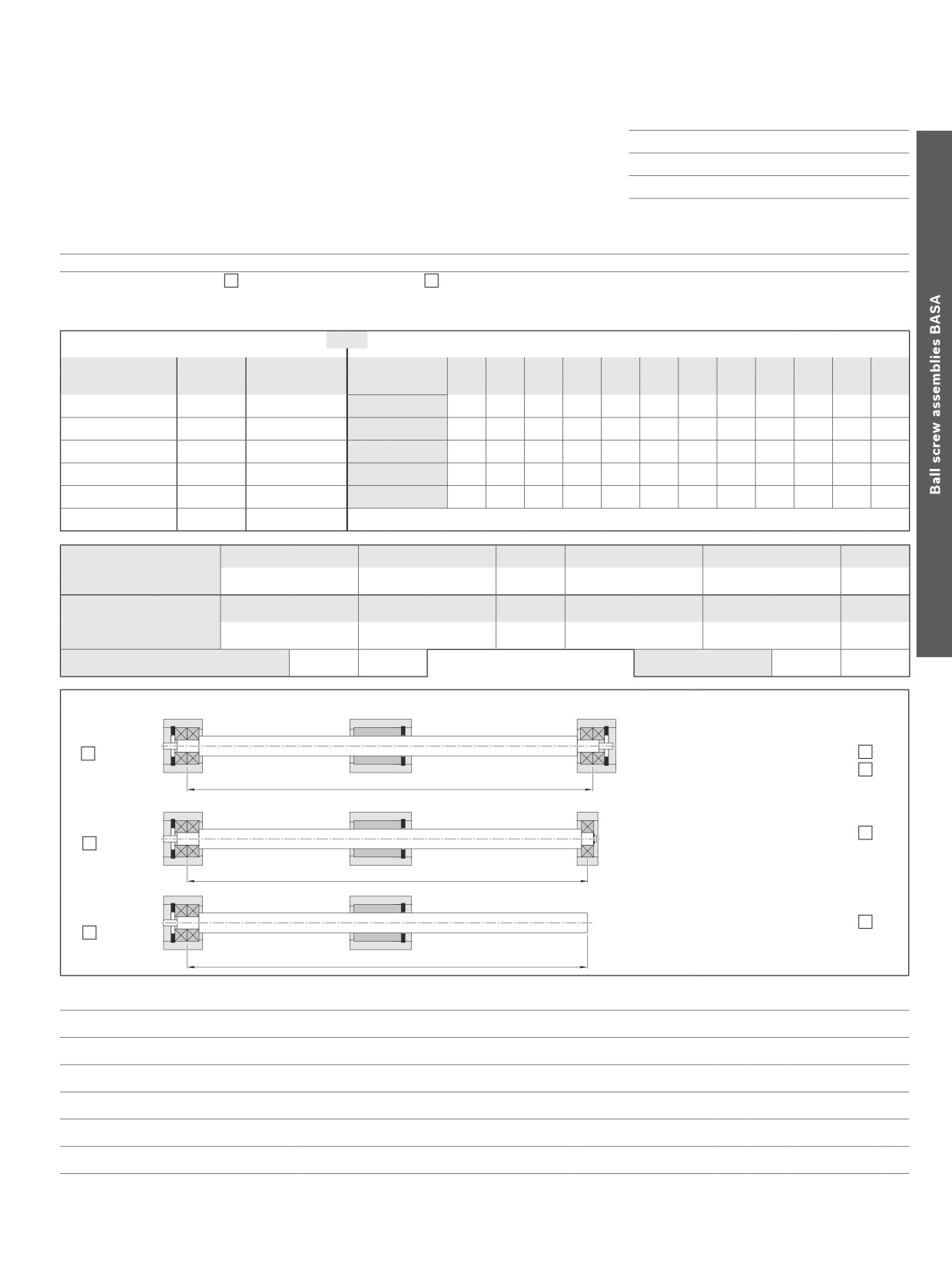
this connection, the intersection point of the
axial and radial bearing load must be below the
muss boundary for a bearing to be suitable for
Static limit load
7000
the application.
6500
6000
5500
5000
4500
4000
3500
3000
2500
2000
1500
1000
LGL-D-0624
500
LGL-A-1244
0
LGL-A-1547
0
400
800
1200
1600
2000
2400
2800
LGL-A-2060
Axial bearing load Fax (N)
Average speed and average bearing load
3
n1
qt1
n2
qt2
qtn
nn
When the bearing load varies in steps over
Fm
Fcomb13
Fcomb23
Fcombn3
22
n
m
100
nm
100
nm
100
a specific period of time 22, calculate the
dynamic equivalent bearing.
q1
q2
qn
n
n1+
n2
nn
23
When the speed varies, use formula 23. In
m
100
100
100
these formulas qt
denotes the discrete time
Fcomb1 ... Fcombn = combined equivalent axial load in phases 1 ... n
(N)
steps for the individual phases in %.
Fm
= dynamic equivalent bearing load
(N)
n1 ... nn
= speeds in phases 1 ... n
(rpm)
nm
= average speed
(rpm)
qt1 ... qtn
= discrete time steps in phases 1 ... n
(%)
Service life and load safety factor
3
C
C
= dynamic bearing load rating
(N)
L
· 106
24
Fm
Fm
= combined equivalent load on bearing
(N)
L
= nominal service life in revolutions
(-)
Nominal service life
Lh
= nominal service life in operating hours
(h)
The nominal service life is calculated as
3
nm
= average speed
(rpm)
follows:
16 666
C
L
·
25
h
nm
Fm
Attention:
Pay attention to the dynamic load rating
of the nut!
Static load safety factor
F0max = maximum static load
(N)
C0
The static load safety factor for machine
S
0 =
26
C0
= static load capacity
(N)
F0max
tools should not be lower than 4.
S0
= static load safety factor
(-)
183
Design Calculation Service Form
Bosch Rexroth
Company:
Linear Motion Technology
Contact:
E-mail:
97419 Schweinfurt / Germany
Telephone:
Find your local contact person here: www.boschrexroth.com/adressen
Application
New design
Revised design
Operating conditions
Discrete time step parameters
or
Dynamic cycle parameters
Discrete time steps
Speed
Action of force x
Section
T1
T2
T3
T4
T5
T6
T7
T8
T9
T10
T11
T12
(%)
(1/min)
T1 =
n1 =
Path
(mm)
T2 =
n2 =
V
(m/s)
T3 =
n3 =
a
(m/s2)
T4 =
n4 =
Time
(s)
T5 =
n5 =
Action of force x
T6 =
n6 =
F1
F2
F3
F4
F5
F6
Forces
(N) =
m1
m2
m3
m4
m5
m6
Mass
(kg) =
Bearing center-to-center distance
(mm) =
or
Max. stroke
(mm) =
Bearing type
Installation Position
1.
Tight
Tight
Horizontal
Vertikal
Ls
Drawing enclosed
2.
Tight
Loose
(recommended)
Ls
Delivery with bearing
3.
Tight
Free
Ls
Required life:
Operating temperature:
°C Up to
°C
Type of lubrication:
Short description of the application / unusual operating conditions:
Visit out official homepage and use the provided configurators and our dimensioning program Linear Motion Designer free of charge.
184
Screw Assemblies | Ball Screw Assemblies BASA
Planetary Screw Assemblies PLSA |
189
Planetary Screw Assemblies PLSA
R999001185/2020-03 Bosch Rexroth AG

190
Screw Assemblies | Planetary Screw Assemblies PLSA
New features at a glance
New features at a glance
The divided FDM-E-S of the Single Nut with flange nut type has been discontinued.
cc
FDM-E-S
New screw sizes 25x5 and 25x10
To add to our product portfolio, the intermediate sizes 25 with leads 5 and 10 have been
issued.
This size is available for the nut types Cylindrical Single Nut ZEM-E-S and Single Nut with
flange FEM-E-S.
Cover plate wiper
To expand on our seal system, the cover plate wiper has been issued.
This is suitable especially for applications in the temperature range of 60° and higher.
cc
Cover plate wiper
without friction torque,
Expansion of the documentation
TRD = 0 Nm
Option 5 = Two-point compensation
This kind of documentation is intended to compensate for the lead error of a screw.
Planetary Screw Assemblies PLSA |
191
Table of contents
Table of contents Planetary screw assemblies
New features at a glance
190
Installation
256
Installation Tolerances
258
Table of contents
191
Lubrication
259
Product overview
192
Nuts, Screws, Screw Ends, Bearings
192
Calculation
262
Planetary Screw Assembly - Definition
193
End Bearings
268
Sample applications
194
End Bearings
268
Lubrication of the end bearings
269
Inquiries and orders
196
Design Calculation Service Form
272
Overview of formats/abbreviations
198
Further information
273
Nuts
198
Cylindrical single nut ZEM-E-S
198
Single nut with flange FEM-E-S
200
Screws
202
Precision screw PSR
202
Screw ends
204
Abbreviations
205
Form 002
205
Form 112, 122
206
Form 132, 142
208
Form 212, 222
210
Form 312
212
Form 412
214
Form 512, 522
216
Form 532, 542
218
Form 612, 622
220
Form 812, 822
224
Form 832, 842
226
Accessories
232
Overview
232
Bearing assembly LAF
234
Bearing assembly LAN
236
Bearing assembly LAD
238
Bearing assembly LAS
240
Bearing assembly FEC-F
242
Slotted nuts NMA for fixed bearings
244
Ring nut GWR
245
Measuring pads
246
Technical data
248
Technical notes
248
Acceptance Conditions and Tolerance Grades
251
Preload, Rigidity, Friction Torques
254
192
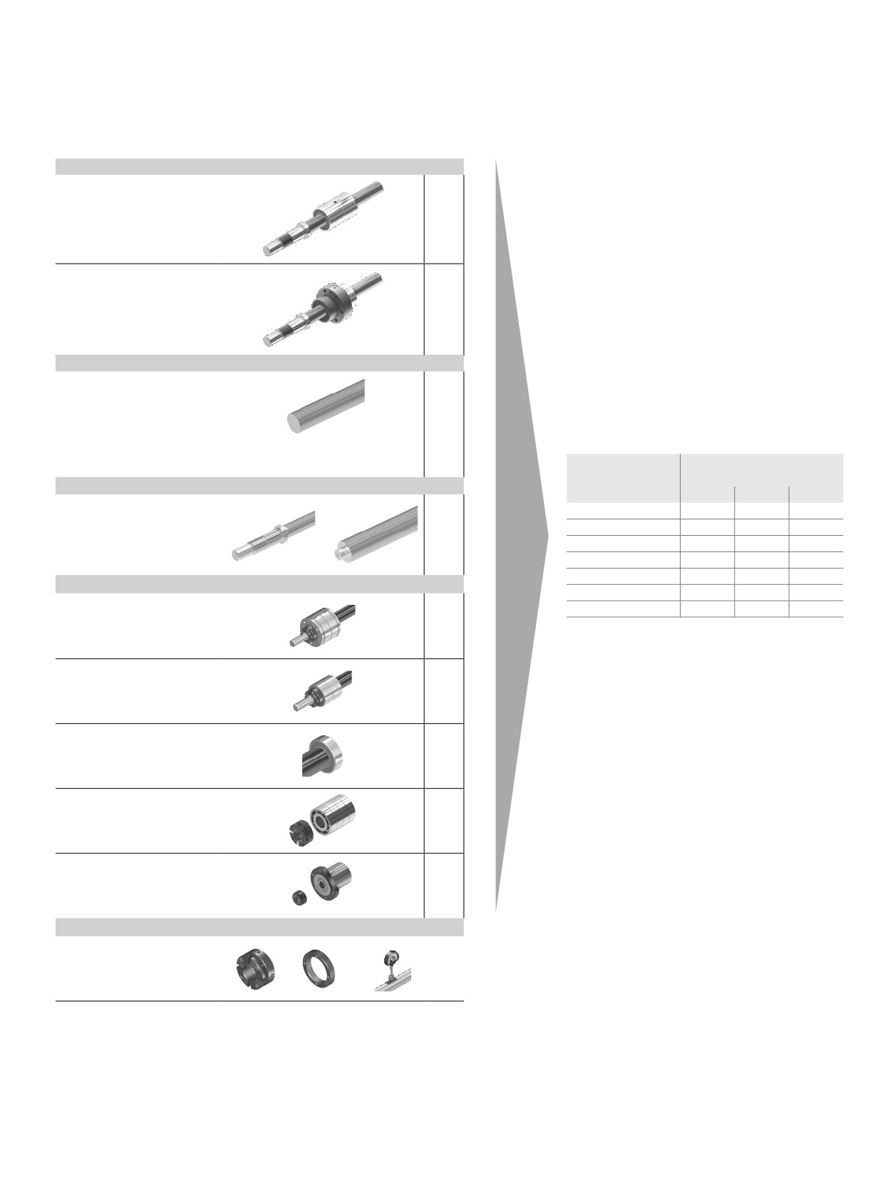
Screw Assemblies | Planetary Screw Assemblies PLSA
Product overview
Nuts, Screws, Screw Ends, Bearings
Nuts
Page
Cylindrical single nut
198
ZEM-E-S
Preload class: C0, C2
Single nut with flange
200
FEM-E-S
Preload class: C0, C2
Screws
Precision screw PSR
202
Tolerance grades
T5, T7, T9
Acceptance conditions
251
Diameter d0
Lead P
(mm)
(mm)
Screw ends
5
10
20
210
20
X
-
-
25
X
X
-
30
X
X
-
39
X
X
-
48
X
X
-
Bearing
60
-
X
X
LAF
234
75
-
X
X
LAN
236
LAD
238
LAS
240
FEC-F
242
Accessories
Slotted nut NMA
244
Ring nut GWR
245
Measuring pads
246
Planetary Screw Assemblies PLSA |
193
Product overview
Product overview
Planetary Screw Assembly - Definition
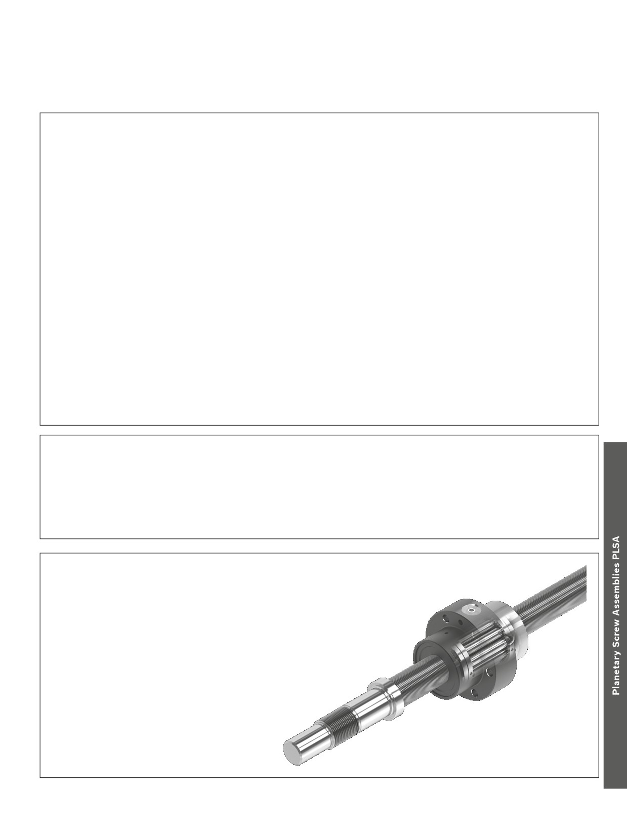
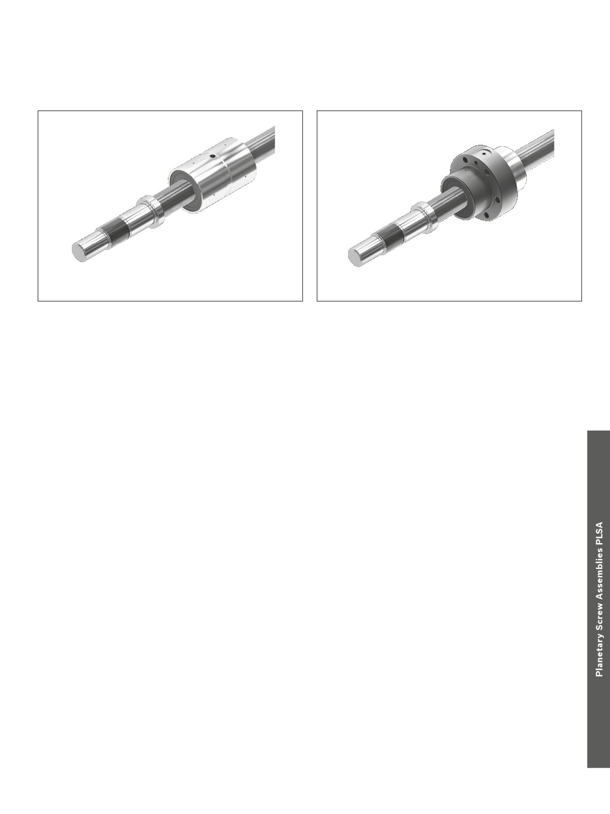
The Planetary Screw Assembly PLSA is a complete cylindrical screw assembly with planets as the rolling elements. It serves to
convert rotary motion into linear motion and vice versa.
The basic functioning of a Planetary Screw Assembly is easy to describe, but the range of designs and the requirements for
practical applications are many and varied.
Planetary Screw Assemblies are designed to transmit high forces and thus round off the upper end of the screw assembly
product portfolio.
Planetary Screw Assemblies are drive technology screw assemblies in which threaded rollers
(the planets) are housed in a threaded nut, their ends being lodged in discs with holes arranged around a pitch circle so that
they rotate axially parallel to the special threaded screw, causing the nut to move linearly along the screw.
Rexroth Planetary Screw Assemblies offer design engineers many
At each end of the nut there are internally geared rims which
opportunities to solve transport and positioning tasks with a driven
engage with the external gearing on the planets. Guide discs
screw. At Rexroth you will be sure to find exactly the kind of tailor-
inside the gear rims support the planets’ journals and ensure that
made products you need for special applications.
they are correctly spaced. The discs also prevent coarse dirt from
working its way into the nut.
Structural design:
Both the screw and the nut have an identical multi-start profile
Versions:
with a flank angle of 90°.
--
Cylindrical single nut with backlash or preload (ZEM-E-S)
The planets have journals at both ends, which are lodged in holes
-–
Single nut with flange with backlash or preload (FEM-E-S)
bored in the guide discs. The toothed ends of the planets engage
with the internal gear rims of the nut. The planets have single-start
threads and crowned flanks that roll without slipping along the nut
threads.
Precision Screws PSR
We have now transferred this tried and trusted manufacturing
Bosch Rexroth has a long tradition of manufacturing precision
technology to the screws of our Panetary Screw Assemblies.
screws. Offered in many sizes and in unmatched quality, these
For users, this results in many advantages, including the following:
have been an integral part of our Ball Screw Assembly product
--
Identical quality to Rexroth Ball Screw Assemblies
range for years.
--
Fast delivery
-–
Attractive prices thanks to cost-effective manufacturing
Benefits
--
Smooth functioning due to the principle of
synchronized planets
--
Very low noise
-–
High linear travel speeds
-–
Large number of contact points
-–
High load ratings
-–
High mechanical efficiency
-–
Long service life
-–
Compact design
-–
High power density
-–
Effective, wiping sealing
-–
Low lubricant consumption
-–
Pre-tensioned units available
-–
High positioning accuracy and repeatability
194
Screw Assemblies | Planetary Screw Assemblies PLSA
Sample applications
Sample applications
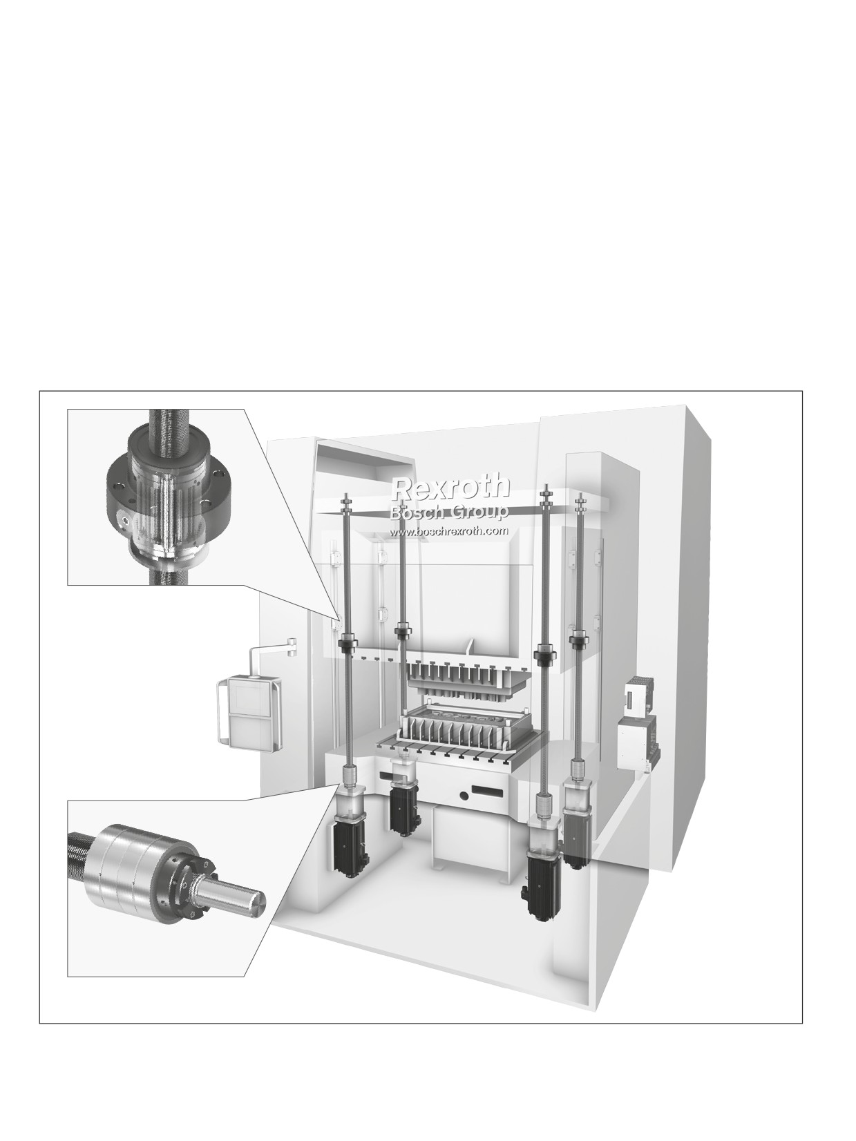
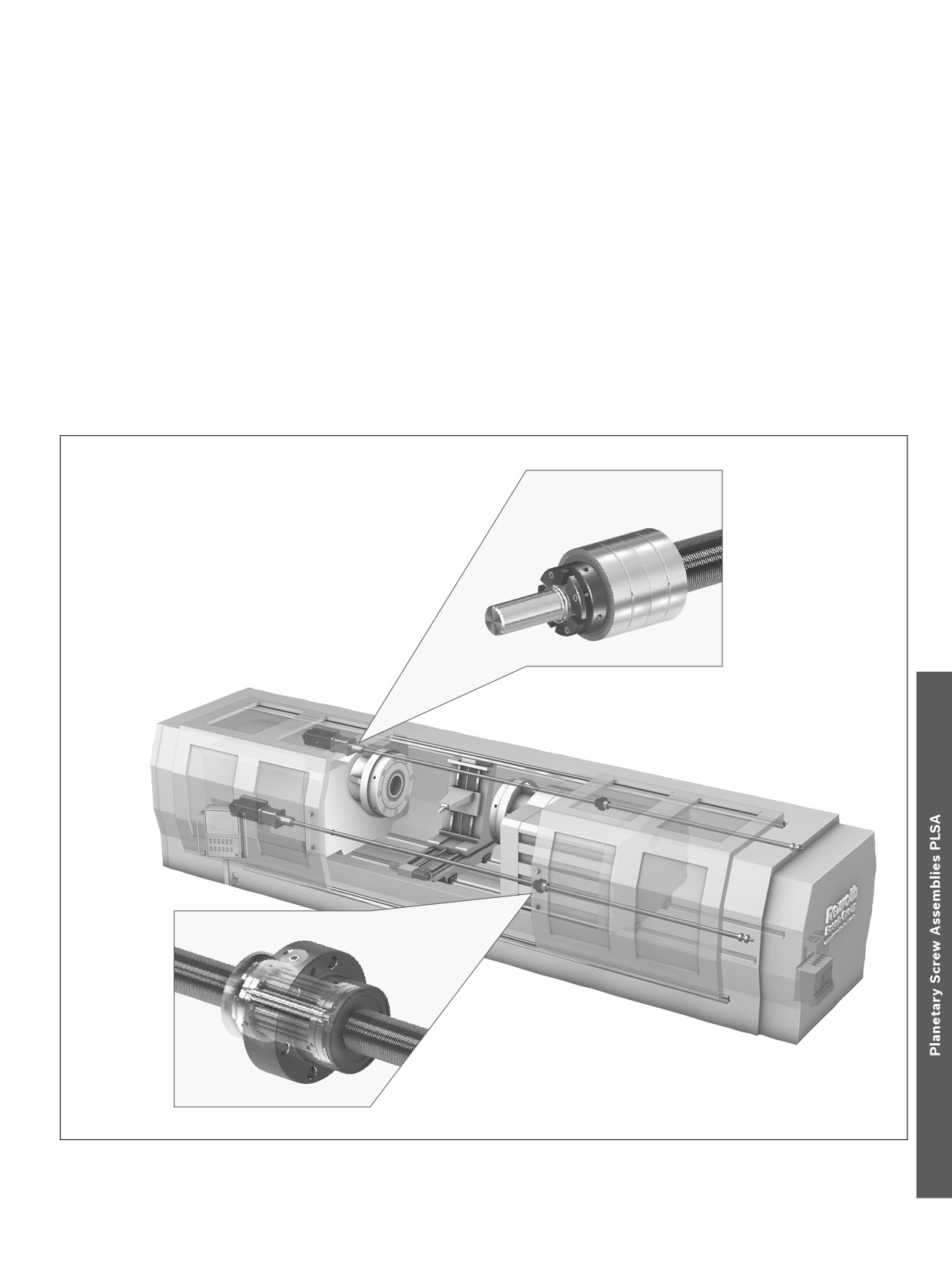
Rexroth Planetary Screw Assemblies are used with great suc-
cess in many different application areas:
--
Food and packaging industries
--
Plastic injection molding machines
-–
Printing and paper industry
-–
Machine tools
-–
Medical technology
-–
Measuring and material testing machines
-–
Cutting operations
-–
Robots
-–
Forming operations
-–
Automotive industry
-–
Metals industry
-–
Aerospace industry
-–
Automation and handling
Electric press
Planetary Screw Assemblies PLSA |
195
Sample applications
Friction welding machine
196
Screw Assemblies | Planetary Screw Assemblies PLSA
Inquiries and orders
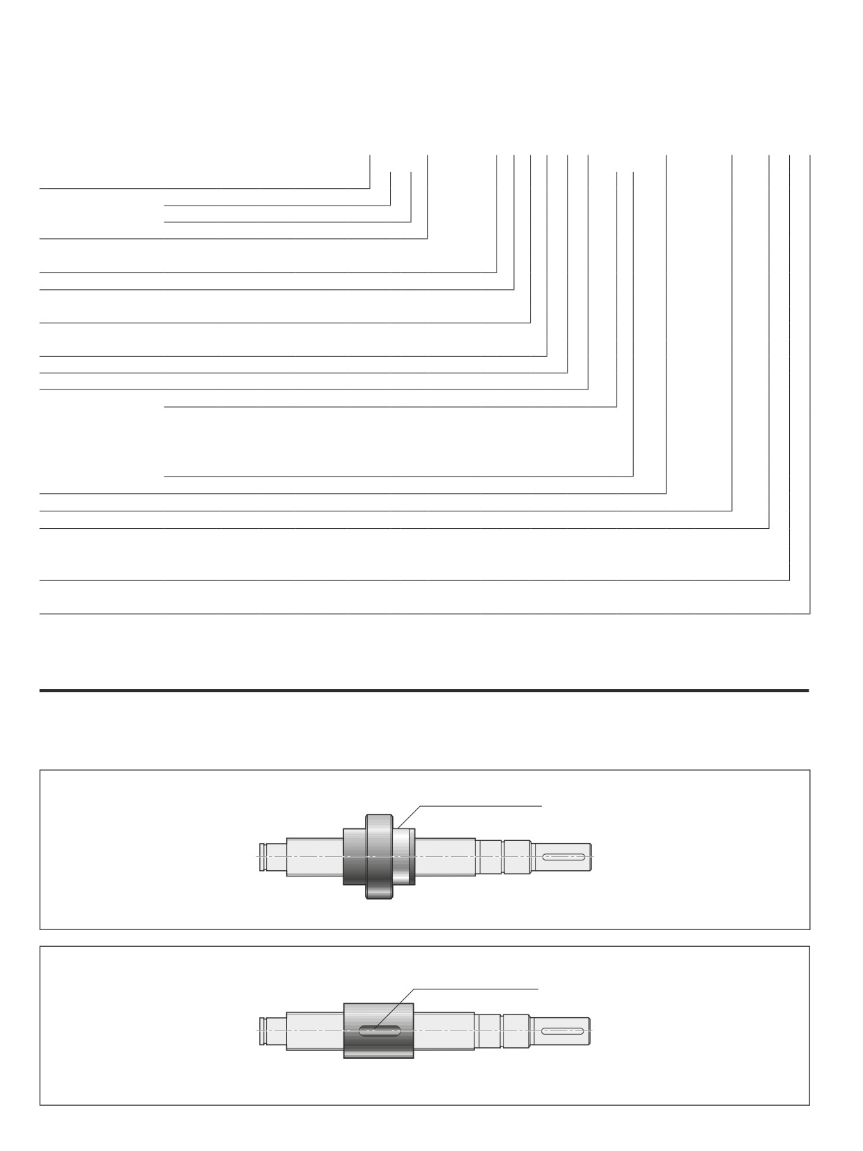
Identification system for short product names PLSA / ordering data
Planetary Screw Assembly
PLSA
20 x 5 R
FEM-E-S
00
1
0
T7
R
812
Z
120
412
Z 120
1250
1
1
Planetary Screw Assembly
Size
Nominal diameter (mm)
Lead (mm)
Direction of lead, R … right
Nut type
ZEM-E-S Cylindrical Single Nut
FEM-E-S Single nut with flange
Nut rework
00 … no rework
Sealing system
0 … without
4 … gap-type seal (standard)
1 … lip-type seal
5 … Wiper
Preload classes
0 … C0 (standard backlash)
1 … C2 (average preload)
Accuracy
T5, T7, T9
Screw
R ... Precision screw
Left screw end
Form:
… standard form
Option:
Z… centering as per DIN 332-D
S… hex socket
G… female thread
K … none
Versions:
Right screw end
... see left screw end
Overall length [mm]
Documentation
1 … standard (acceptance test report)
5 … Two-point compensation
2 … torque test report
6 … lead and torque test report
3 … lead test report
Lubrication
1 … preserved and nut with basic greasing
2 … preserved
Mounting direction of nut types
Definition: The centering diameter on nuts with a flange points to the right end of the screw. The mounting direction for cylindrical nuts is
freely selectable (symmetrical).
Centering diameter D1
Symmetrical keyway
Planetary Screw Assemblies PLSA |
197
Inquiries and orders
Overview of formats
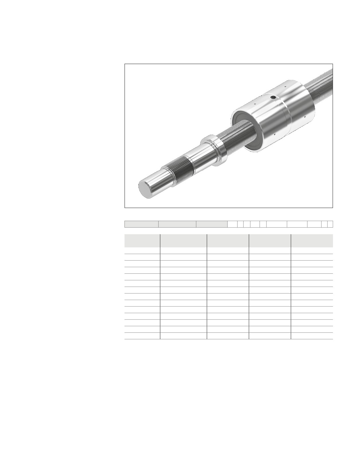
ZEM-E-S
FEM-E-S
Abbreviations
C
= dynamic load rating
MAG
= tightening torque of set screw
C0
= static load rating
MRL
= bearing friction torque with seal
d0 x P = size
Mp
= Maximum permissible drive torque
d0
= nominal diameter
(condition: no radial load at drive journal)
FaB
= axial breaking load of slotted nut
Rfb
= rigidity (axial)
G
= female thread
Rkl
= rigidity against tilting
Js
= moment of inertia
P
= lead (R = right-hand)
nG
= limit speed (grease)
vmax
= maximum speed
No.
= part number
S
= hex socket
MA
= tightening torque of slotted nut
Z
= centering hole
198
Screw Assemblies | Planetary Screw Assemblies PLSA
Nuts
Overview of formats/abbreviations
Cylindrical single nut ZEM-E-S
--
With standard seals
-–
Preload class: C0, C2
-–
For precision screws PSR in tolerance
grade T5, T7, T9 (with backlash only)
Note: Delivered only as a complete unit
Ordering code PLSA:
PLSA
20 x 5R
ZEM-E-S
00
4
0
T7
R
822Z150
412Z120
1250
1
1
d0 x P
no.
C1)
C01)
vmax2)
(kN)
(kN)
(m/min)
20 x 5R
R157C A10 03
55
80
37.5
20 x 5R
R157C A10 13
55
80
37.5
25 x 5R
R157C 210 03
65
122
30.0
25 x 10R
R157C 230 03
74
118
60.0
30 x 5R
R157C 310 13
87
178
25.0
30 x 10R
R157C 330 03
101
174
50.0
39 x 5R
R157C 410 03
123
269
19.2
39 x 10R
R157C 430 03
145
271
38.4
48 x 5R
R157C 610 03
188
481
15.6
48 x 10R
R157C 630 03
220
475
31.2
60 x 10R
R157C 730 03
322
780
25.0
60 x 20R
R157C 770 03
375
786
50.0
75 x 10R
R157C 830 03
480
1,487
20.0
75 x 20R
R157C 870 03
544
1,496
40.0
1) The load ratings are valid for tolerance grade T5 only.
For other tolerance grades, please consider the correction factor fac on Page 249.
2) See “Characteristic speed” on page 249 and “Critical speed ncr” on page 266
For the codes, see the chapter entitled “Abbreviations”