Rexroth: Screw Assemblies. Catalog (R999001185/2020-03) - page 12
165
Calculation and examples
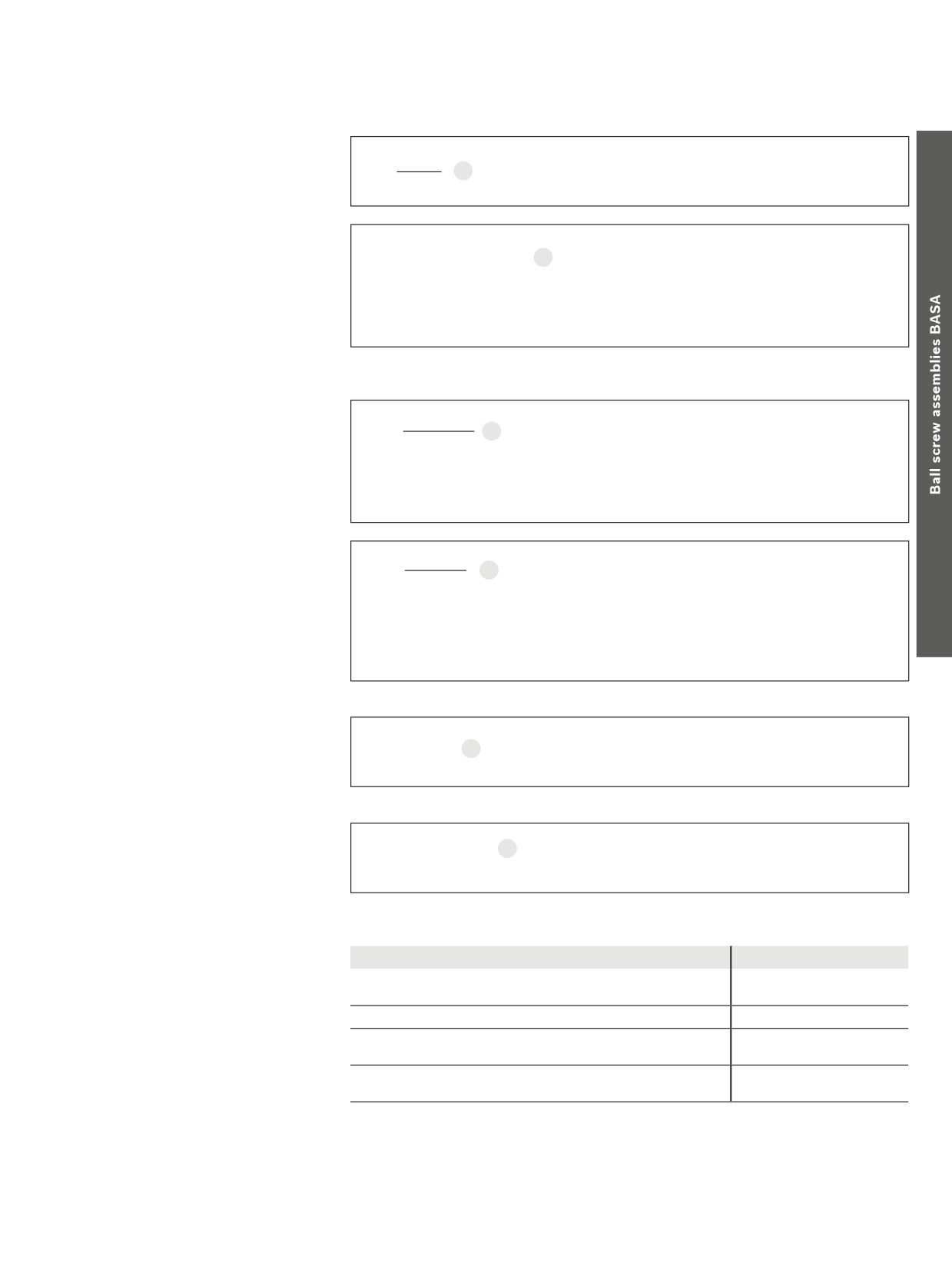
Service life in hours Lh
Lh
= Service life
(hrs)
L
Lh =
7
L
= service life in revolutions
(-)
nm · 60
nm
= average speed
(rpm)
DCmachine
= duty cycle of the machine
(%)
DCmachine
Lh machine = Lh ·
8
DCBASA
= duty cycle of the BASA
(%)
DCBASA
Lh machine
= nominal service life of the
machine
(h)
Lh
= nominal service life of the
Ball Screw Assembly
(h)
Drive torque and drive power
You must check end machining for the
maximum permissible torque
FL
= thrust force
(N)
FL · P
Mta =
9
Mp = maximum permissible drive torque
(Nm)
2000 · π · η
Mta = drive torque
(Nm)
Drive torque Mta
Mta ≤ Mp
P
= lead
(mm)
For conversion of rotary motion to linear
η
= mech. efficiency (η ≈ 0.9)
(-)
motion
Transmitted torque Mte
FL
= thrust force
(N)
FL · P · η’
for conversion of linear motion into rotary
Mte =
10
2000 · π
motion:
Mp = maximum permissible drive torque
(Nm)
Mte = transmitted torque
(Nm)
Mte ≤ Mp
P
= lead
(mm)
η´
= mech. efficiency (η´ ≈ 0.8)
(-)
The dynamic drag torque must be taken into account for preloaded nut units.
Drive power Pa
Mta = drive torque
(Nm)
Mta · n
Pa =
11
n
= speed
(rpm)
9 550
Pa
= drive power
(kW)
cc
With critical applications, you must
C0
= Static load rating
(N)
S0 = C0 / (F0 max
)
12
pay attention to the information below.
F0 max = Maximum static load
(N)
S0
= Static load safety factor
(-)
Static load safety factor S0
You must verify mathematically any struc-
tural design involving rolling contact with
Design of the static load safety factor in relation to the operating conditions
regard to the static load safety factor.
Operating conditions
Static load safety factor S0
In this connection, F0 max represents the
Overhead arrangements and applications representing a high
≥ 12
maximum load amplitude that can occur,
hazard potential
which can affect the screw drive.
High dynamic load when at standstill, contamination.
8 - 12
It does not matter whether this load is
Normal design of machinery and plant without full knowledge of the
exerted only for a short period.
5 - 8
load parameters or connection details.
It may represent the peak amplitude of an
Full knowledge of all the load data.
overall dynamic loading.
3 - 5
Vibration-free operation is ensured.
For design purposes, the data shown in the
table applies.
If there are health and safety hazards, protection against falling loads must be provided
(see the chapter entitled “Arrestor nut”)
166
Screw Assemblies | Ball Screw Assemblies BASA
Calculation and examples
Calculation
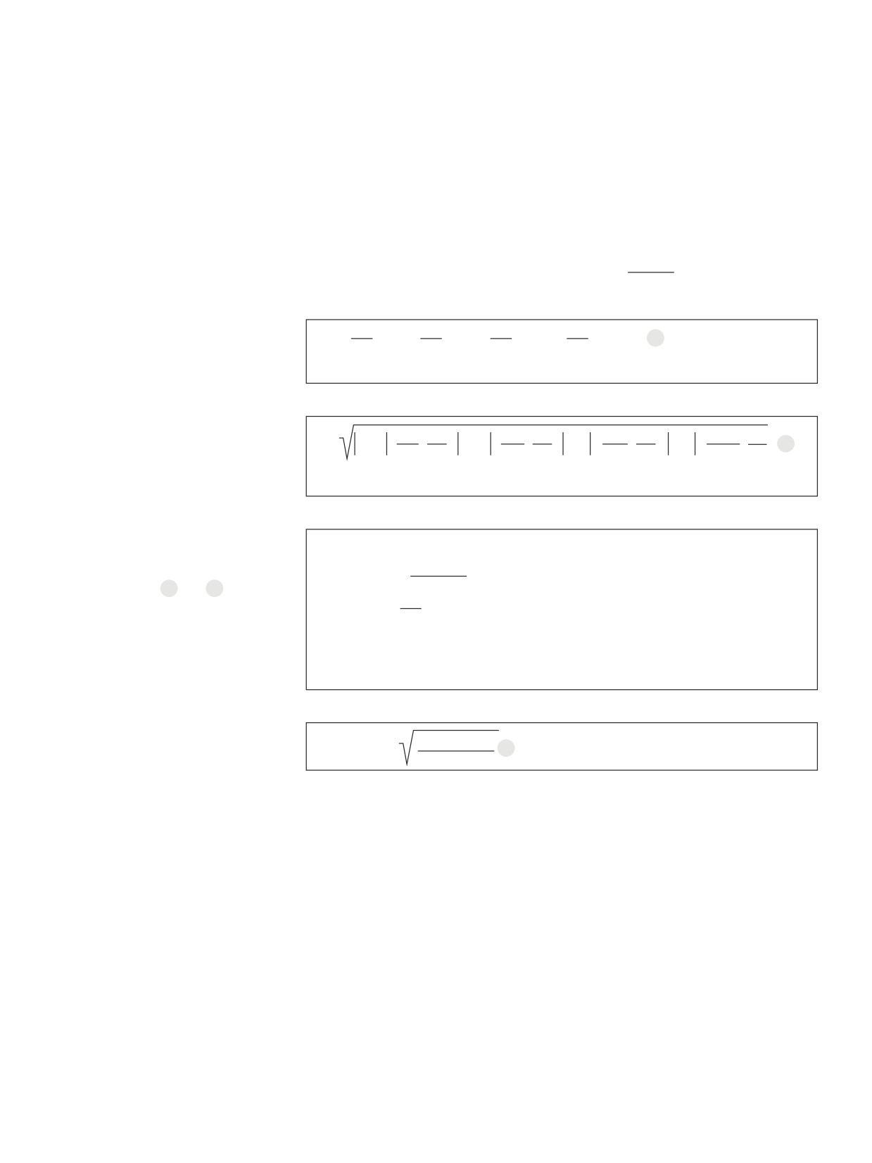
Calculation example Service life
Proposed BASA: 63 x 10
Operating conditions
F1
=
50 000 N at n1 =
10 rpm for q1 =
6% of the duty cycle
The service life of the machine should be
F2
=
25 000 N at n2 =
30 rpm for q2 =
22% of the duty cycle
40,000 operating hours with the BASA
F3
=
8 000 N at n3 =
100 rpm for q3 =
47% of the duty cycle
operating 60% of the time.
F4
=
2 000 N at n4 =
1000 rpm for q4 =
25% of the duty cycle
100%
Calculation procedure
6
22
47
25
nm =
·
|10| +
·
|30| +
·
|100| +
·
|1000|
1
100
100
100
100
Average torque nm
nm = 304 rpm
Average load Fm for variable load and
3
3
|10|
6
3
|30|
22
3 |100|
47
3 |1000|
25
variable speed
F
m =
50000 ·
·
+
25000
·
·
+
8000
·
·
+
2000
·
·
3
304
100
304
100
304
100
304
100
Fm = 8 757 N
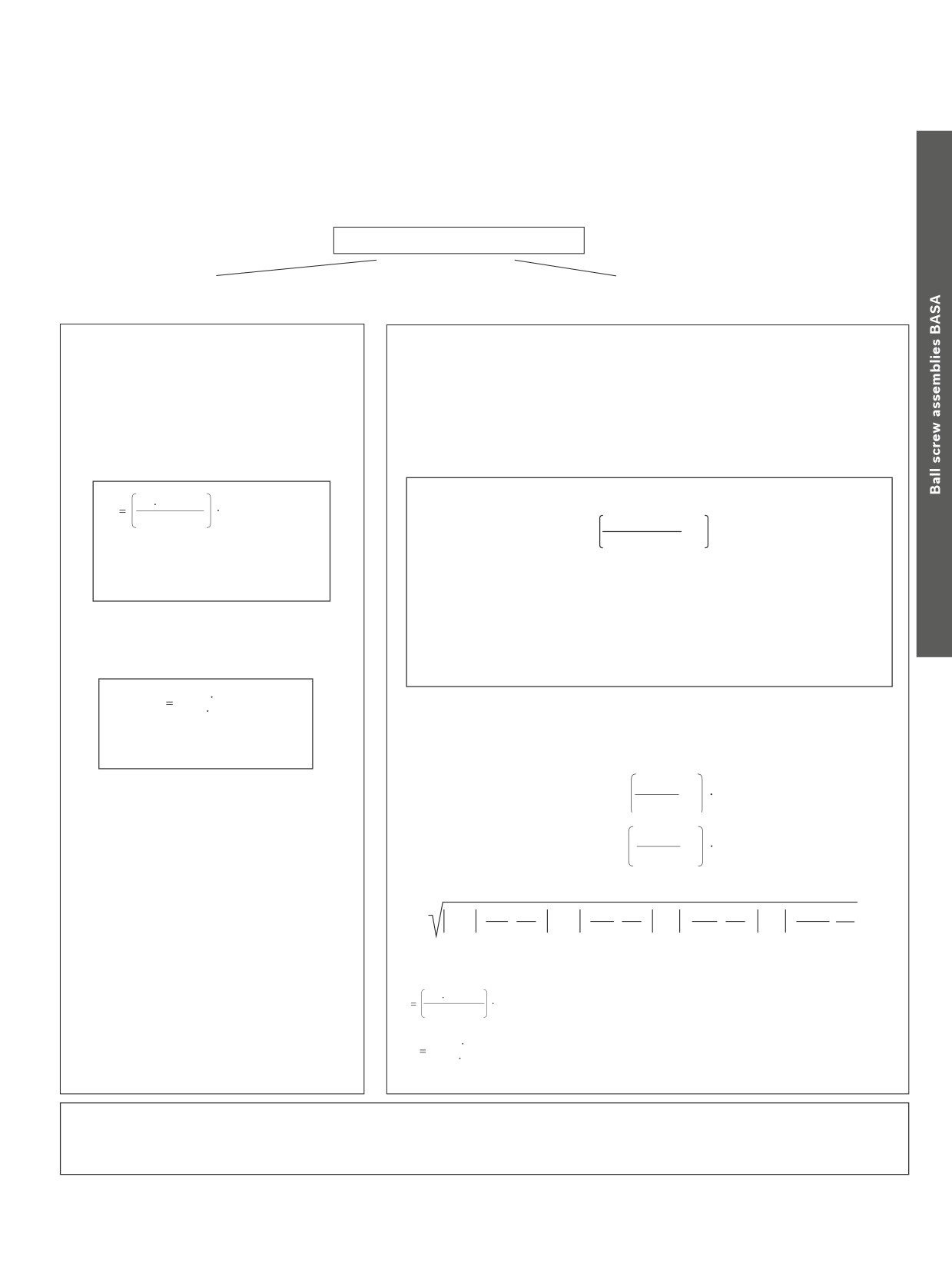
Required service life L
L
= Lh · nm · 60
(revolutions)
DCBASA
The service life L can be calculated by
Lh = Lh machine ·
DCmachine
transposing formulas
7 and
8 :
60
Lh = 40 000 ·
= 24000 h
100
L
= 24 000 · 304 · 60
L = 437,760,000 revolutions
Basic dynamic load rating C
3
437 760 000
C = 8 757 ·
5
C ≈ 66 492 N
106
Result and selection
Now a selection can be made from the
e.g. Ball Screw Assembly,
dimension tables:
size 63 x 10 R x 6-6, with preloaded
Attention:
FEM-E-S single flange nut,
Take into account the dynamic load rating
dyn. load capacity C = 106,600 N,
of the screw end bearing used!
part no. R1512 640 13,
with screw tolerance grade 7.
cc
Take into account correction factor
fac of the tolerance grade! See page 141.
167
Calculation and examples
Cross-check
Now the following can be selected from the product tables:
Size 63 x 10 R x 6-6
Backlash (C0)
Preload
(preload class C3)
FEM-E-S, with standard backlash
FEM-E-S, with preload class C3
Load rating Cdyn = 106,560 N
Load rating Cdyn = 106,560 N
correction factor fac = 0.9
Correction factor fac = 0.9
Cross-check
Pre-tensioning force = 4400 N
Service life of the selected ball
Cross-check
screw drive in revolutions
The following applies to the effective
equivalent bearing load:
3
F
>
2.8 · Fpr
= |Fn|
Feff n
0,9 106 560
3
L
106
8 757
2
|Fn|
F
≤
2.8 · Fpr
Feff n
=
+ 1
· Fpr
2.8 · F
pr
L ≈ 1314 · 106 revolutions
C
= dynamic load rating
(N)
Feff n = effective equivalent axial load during phase n
(N)
Fn
= axial load during phase n
(N)
Fpr
= pre-tensioning force (see tables on pages 148/151)
(N)
Service life in hours Lh
1 314 106
L
h
2,8 x Fpr = 2.8 x 4 440 N = 12 432 N
304
60
Lh ≈ 72,039 hours
- F1 = 50 000 N > 12 432 N !Feff1 = 50 000 N
- F2 = 25 000 N > 12 432 N !Feff2 = 25 000 N
1,5
- F3 = 8 000 N < 12 432 N !Feff3
=
8 000
4440 N = 9 355 N
12 432+1
1,5
- F4 = 2 000 N < 12 432 N !Feff4 =
2 000
4 440 N = 5 553 N
12 432+1
3
3
|10|
6
3
|30|
22
3 |100|
47
3 |1000|
25
Fm =
50000 ·
·
+
25000
·
·
+
9355
·
·
+
5553
·
·
304
100
304
100
304
100
304
100
Fm = 9 485 N
3
0,9 106 560
L
106
9 485
= 1034 · 106 revolutions
6
1 034 10
L
h
= 56,689 hours
304 60
The service life of both BASAs (with standard backlash C0/with preload class C3) exceeds the required service life
of 40,000 x 60% = 24,000 hours. This means that it is possible to choose a smaller BASA,
subject to a review of it being undertaken.
168
Screw Assemblies | Ball Screw Assemblies BASA
Calculation and examples
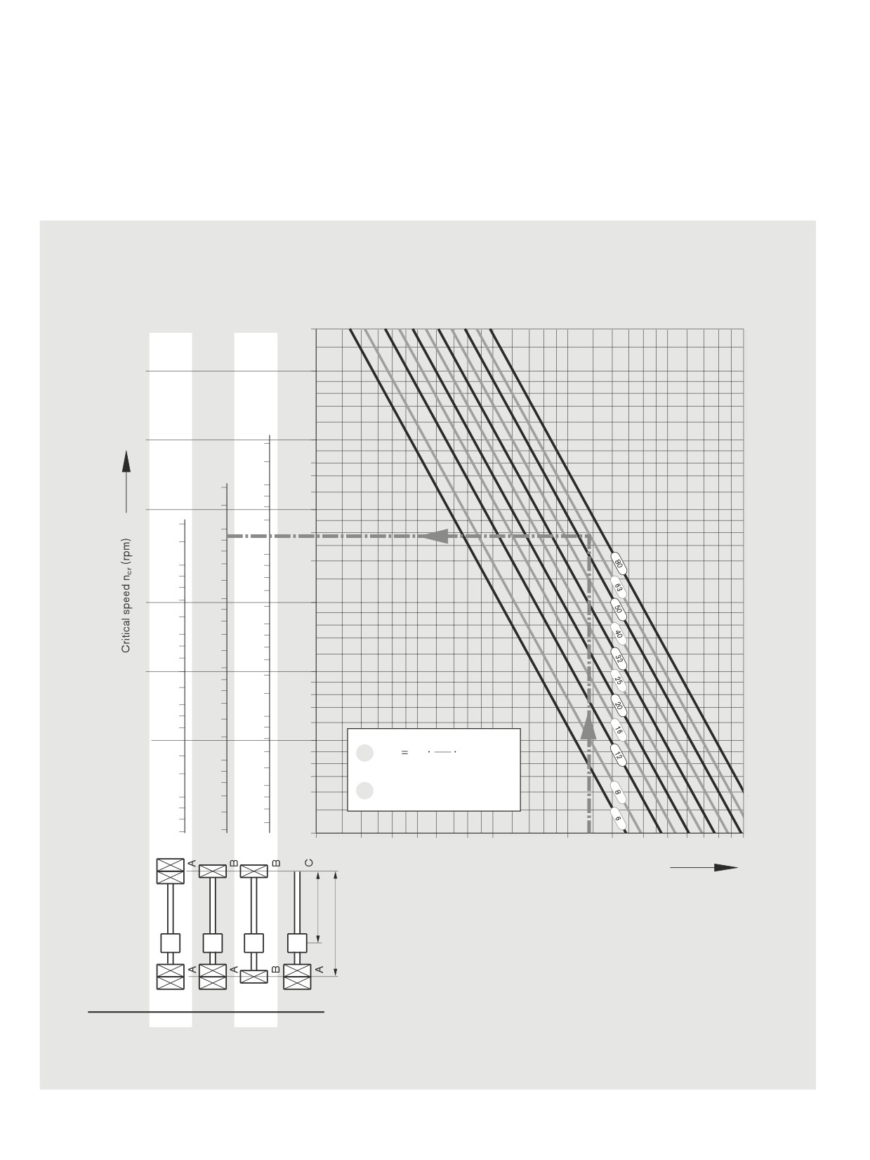
Critical speed ncr
The critical speed ncr depends on the
made for guidance by a nut with backlash.
The characteristic speed and the max. permis-
diameter of the screw, the type of end fixity,
The operating speed should not be more than
sible linear speed must be taken into account,
and the free length lcr. No allowance must be
80% of the critical speed.
see “Technical notes” on page 132.
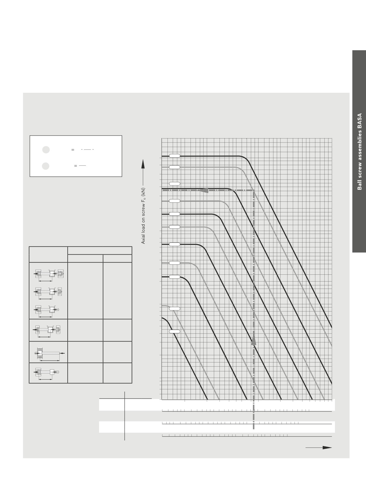
Example
According to the graph, the critical speed
The maximum operating speed in our calculation
Screw diameter
=
63 mm
is 1850 rpm.
example of
Length lcr
=
2.4 m
The permissible operating speed is
n4 = 1000 rpm is therefore below the permissible
End fixity II (fixed bearing - floating bearing)
1850 rpm x 0.8 = 1480 rpm.
operating speed.
3000
2000
1000
3000
800
3000
2000
600
500
3000
2000
400
1000
300
2000
800
1000
200
600
800
500
1000
600
400
800
500
100
300
90
600
400
80
500
70
300
200
60
400
50
d2
7
300
13
ncr fncr
2
10
(rpm)
200
40
lcr
100
ncrp = 0.8 · ncr (rpm)
30
14
200
90
80
70
100
20
200
500
1000
2000
5000
10000
Length lcr (mm)
End fixity:
A = fixed bearing
ncr
= Critical speed
(rpm)
B = floating
lcr
ncrp = Permissible operating speed
(rpm)
bearing
ls
fncr
= Coefficient determined by bearing
C = without
d2
= Root diameter of screw ( see dimension tables)
(mm)
bearing
lcr
= Critical length for preloaded nut systems
(mm)
ls
= Bearing - bearing distance
(mm)
For non-preloaded nut systems lcr = ls
End fixity
I
II
III
IV
For screw ends Form 31, the end fixity can be assumed to be “fixed”.
fncr - value
27.4
18.9
12.1
4.3
Attention: End fixity IV (fixed-floating) - only recommended for short
overall lengths if installed horizontally. For longer overall lengths, the
floating end must be supported. Please contact our specialist department
if you have any questions.
169
Calculation and examples
Permissible axial load on screw Fc (buckling load)
The permissible axial load on the screw Fc
type of end fixity, and the effective unsup-
A safety factor of s ≥ 2 should be taken into
depends on the diameter of the screw, the
ported length lc.
account for axial loading.
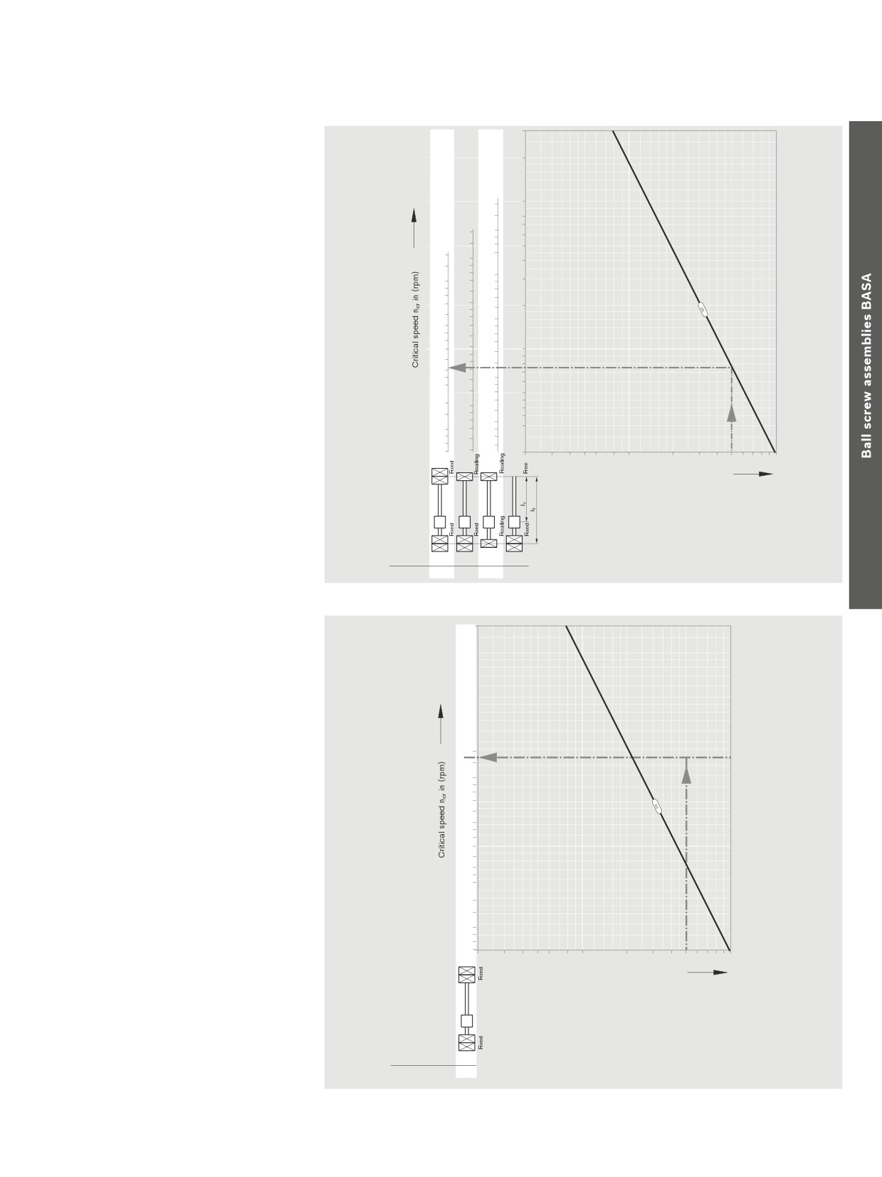
Example
According to the graph, the theoretically
This therefore lies above the maximum operating load
Screw diameter
=
63 mm,
permissible axial load is 360 kN.
of F1 = 50 kN used in our calculation example.
Lead
=
10 mm,
Applying the safety factor 2 yields a
Length lc
=
2.4 m
permissible axial load on the
screw in
End fixity IV (fixed bearing - floating bearing)
operation of 360
kN :
2
= 180
kN.
d24
4
15
F
10
(N)
c fFc
lc2
80
1000
16
F
(N)
800
63
cp
Fc2
600
500
50
Fc
= Theoretically permissible axial load on
400
screw (N)
300
Fcp
= Permissible axial load on screw during
40
operation (N)
200
fFc
= Corrector value determined by bearing
32
d2
= Root diameter of screw, see dimension
tables (mm)
25
100
lc
= unsupported thread length (mm)
90
80
70
20
60
End fixity:
coefficient fFc
50
nut fixed
nut floating
40
16
A - A
30
F
F
12
l
c
20
A - B
End fixity I
End fixity IV
F
F
40.6
20.4
lc
A - C
10
9
8
F
F
8
lc
7
6
B - B
End fixity II
End fixity V
5
F
F
6
lc
20.4
10.2
4
3
A - C
F
F
End fixity III
2
lc
2.6
A - C
F
F
End fixity VI
lc
1,0
2.6
0,9
0,8
0,7
fFc value
End fixity
0,6
0,5
100
500
1000
5000
10000
End fixity:
2.6
III / VI
100
200
500
1000
5000
10000
A = fixed bearing
10.2
V
B = floating bearing
20.4
II / IV
200
500
1000
5000
10000
C = without bearing
40.6
I
200
500
1000
5000
10000
Length lcr (mm)
170
Screw Assemblies | Ball Screw Assemblies BASA
Calculation and examples
Notes on buckling
The effective buckling length lc of the screw is the maximum unsupported screw length in the direction of the force’s flow between the nut
unit and the fixed bearing (center-to-center distance) or between the nut unit and the screw end.
For buckling load calculations, the nut is taken into consideration as a bearing.
For “nut fixed,” the following conditions must be met:
--
zero-backlash nut,
-–
rigid attachment of the nut to the linear guide,
-–
the nut unit is not subjected to moment loads, i.e. a linear guide absorbs any arising moments,
-–
no distortive stresses due to external factors (for example, temperature).
In linear motion systems from Bosch Rexroth, the nut can be considered to be a fixed bearing.
If one or more of the conditions for “nut fixed” are not met, the appropriate coefficients for “nut floating” must be used instead.
Case III occurs in applications with driven nuts, for example, when the nut is stationary and the screw rotates. The nut can then be
regarded as a fixed bearing.
Case VI arises only when the nut unit is not supported by any linear guide.
Design of drive unit FAR-B-S
Fundamental advantages of systems
with driven nuts
Moment of inertia
In the case of long screws, the screw does not have to be rotated in the acceleration
phase, only the nut. The mass moment of inertia of the screw is not therefore critical. The
moment of inertia of the nut is comparatively low and it is no longer dependent on the
required stroke.
Dynamics
The intricate end bearing designs required for high dynamics, for example, fixed bearing on
both ends with angular-contact ball bearings, are no longer necessary.
Screw extenders
Since the screw is stationary, relatively little effort is needed to stretch the screw:
--
Increase in permissible axial loading (buckling load); not limited by end bearings
-–
Compensation of responses to temperature changes
-–
Increase in overall rigidity
--
Improved cooling can easily be provided using a hollow-bored screw:
Liquid cooling
-–
the stationary screw can be cooled with comparatively little effort.
-–
Controlled cooling virtually eliminates changes in length due to temperature fluctuations.
Design and manufacturing tolerances
The use of nuts with a high level of axial and radial runout precision minimizes the induced
screw vibration.
All functional components are supplied from a single source. In-house designs are no
longer needed.
Critical speed
ncr
= Critical speed
(rpm)
d2
ncrp = Perm. operating speed
(rpm)
7
–1
n
10
(min
)
cr fncr
2
fncr
= Coefficient determined
l
cr
by the bearing
ncrp = 0.8 · ncr (rpm)
d2
= For root diameter of screw,
see dimension tables
(mm)
lcr
= Critical length for preloaded
nut systems
(mm)
171
Calculation and examples
3000
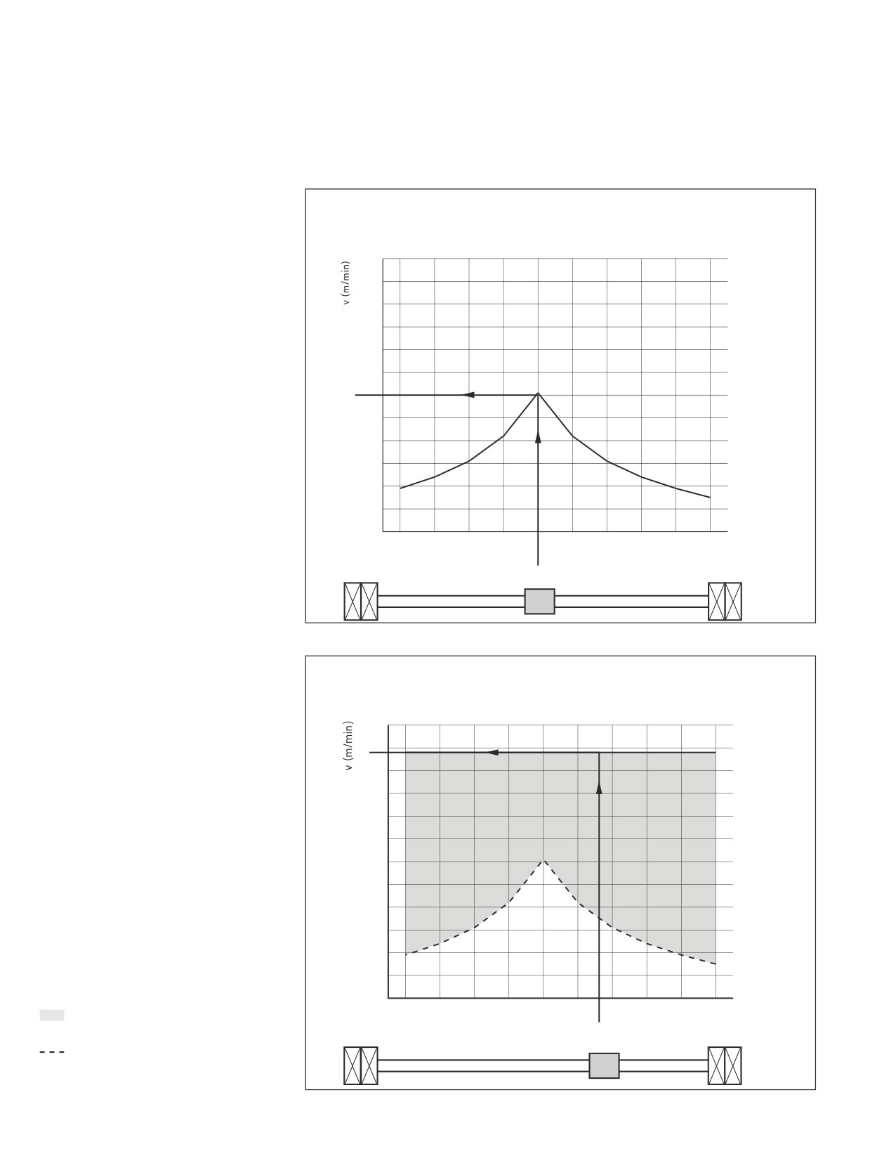
Critical speed with driven screw:
In the case of driven, rotating screws,
2000
there is a critical speed that is
dependent on the different end fixities:
3000
1000
I
Fixed-fixed,
800
II Fixed-floating,
3000
2000
600
III Floating-floating,
500
IV Fixed-free.
3000
2000
400
1000
2000
300
In the case of systems with a driven screw,
800
the bending-critical speed frequently
1000
200
600
represents a limitation on speed that can be
800
500
1000
reached.
600
400
800
500
100
The rotating screw itself generates vibra-
300
600
400
90
80
tions in the system due to the deflection in
500
70
300
200
the horizontal fixity or even due to screw
400
60
50
imbalance. Depending on the free screw
300
Recommended operating
200
40
length and the speed, resonance and very
range
with a driven screw
100
ncr
200
90
30
high amplitudes can result that may destroy
80
70
the system.
100
20
200
500
1000
5000
10000
At the design stage, a safety distance
Length lcr in (mm)
of 20% to the critical speed is generally
maintained.
End fixity
I
II
III
IV
27,4
18,9
12,1
4,3
Fncr value
Critical speed with driven nut:
In the case of systems with a driven nut
and a stationary screw, self-excitation of the
screw is omitted completely with a suitable
design.
The only other things that excite vibrations
are the manufacturing precision of the rotat-
3000
ing nut or of the machine's construction
nmax
of bearing
2700 RPM
Since FAR-B-S drive units only use nuts are
2000
that have been manufactured with a high
degree of axial and radial run-out accuracy,
1000
this means that it is possible to rule out any
800
negative effect on the overall system.
Usable operating range
This means that the bending-critical speed
600
with a driven
nut
500
no longer represents a limitation.
400
The maximum speed of the bearings
300
that are used and, to a lesser extent, the
high maximum permissible rotary speed
200
(d0 x n Wert) of the nut that is used, are still
a limitation.
200
500
1000
5000
10000
Length lcr in (mm)
Note:
Applies to fixed-fixed bearing only
End fixity
I
Fncr
value
27,4
172
Screw Assemblies | Ball Screw Assemblies BASA
Calculation and examples
Design of drive unit FAR-B-S
Permissible travel speed in dependence on the nut position
Permissible travel speed with
Driven screw
a driven nut
Max. permissible travel speed in dependence on the nut position size
End fixity I fixed-fixed bearing
50x40Rx6.5 fixed-fixed bearing on driven screw
End fixity II fixed-floating bearing
120
Parameters:
--
Screw length
100
--
Screw diameter
-–
Lead
-–
End fixity
80
-–
Stretching force, negligible
-–
Max. speed of bearing
-–
D x n value of nut
60
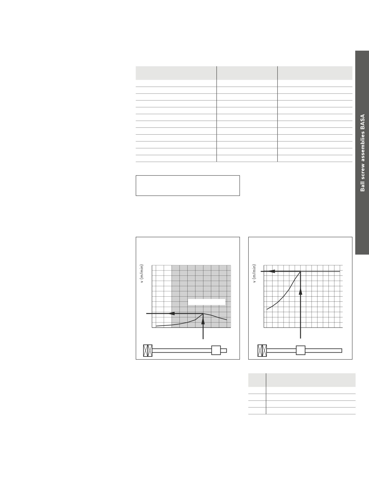
The adjacent diagrams make clear the
40
benefits of a driven nut compared to a
“classical Ball Screw Assembly” with a
driven screw using size 50 x 40R x 6.5 as
20
an example.
In the case of the driven screw (diagram at
the top), the maximum speed with a favor-
0
able nut position in the center of the screw
500
1000
1500
2000
2500
3000
3500
4000
4500
5000
is about 60 m/min. However, this speed is
only achieved in one position of the stroke.
Nut position (mm)
In the case of a non-central nut position,
however, it is only possible to achieve about
20 m/min, since the necessary support for
the screw is missing. This means that the
potential for a high characteristic speed of
the nut (d x n value) cannot be achieved in
Driven nut
practice.
Max. permissible linear speed
Driven nut
Size 50x40Rx6.5 with fixed-fixed bearing with driven nut
With the driven nut (diagram at the bottom
120
for end fixity I “fixed-fixed”), however, the
permissible travel speed of the driven nut
is 108 m/min regardless of the nut position
100
across the entire stroke.
In the case of end fixity II “fixed-floating”,
the floating bearing (axial displacement
80
possible) can be designed such that it is
possible to achieve a tangential gradient of
the bending line (bending angle at journal
60
area = 0).
In this case, you can also consider a float-
ing bearing end like this as being a fixed
40
bearing for the calculation.
20
0
Improved performance with driven nut
500
1000
1500
2000 2500 3000 3500 4000
4500
5000
Nut position (mm)
Driven screw
173
Calculation and examples
FAR-B-S size
Speed nmax
Speed vmaxFAR
For the permissible RPM and travel
d0 x P x Dw - i
(rpm)
(m/min)
speeds of FAR-B-S drive units, refer to
32 x 10R x 3.969 - 5
3,000
30
the table below:
32 x 20R x 3.969 - 3
3,000
60
32 x 32R x 3.969 - 3
3,000
96
40 x 10R x 6 - 5
2,800
28
End fixity I fixed-fixed bearing and end
40 x 20R x 6 - 3
2,800
56
fixity II fixed-floating bearing
40 x 40R x 6 - 3
2,800
112
50 x 10R x 6 - 6
2,700
27
50 x 20R x 6.5 - 5
2,700
54
50 x 40R x 6.5 - 3
2,700
108
63 x 10R x 6 - 6
2,300
23
63 x 20R x 6.5 - 5
2,300
46
63 x 40R x 6.5 - 3
2,300
92
Conversion of rotational speed to velocity
nmax · P
vmax = velocity
(m/min)
vmax =
1000
P
= lead
(mm)
nmax = rotational speed
(RPM)
End fixity III floating-floating bearing
This type of end fixity is virtually never used.
Critical speed with rotating nut and
Driven nut
Driven nut
screw clamping end fixity IV fixed-free
Max. permissible linear speed
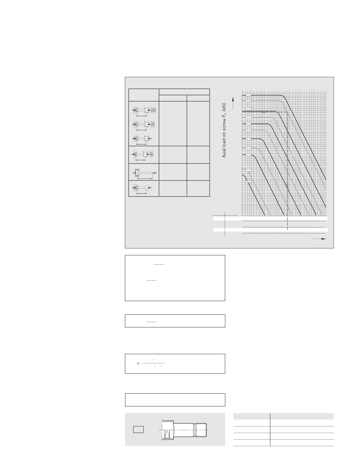
Max. permissible linear speed
bearing
Size 50x40Rx6.5 with fixed-free bearing
Size 50x40Rx6.5 with fixed-free bearing
In the case of “fixed-free” systems with
120
120
a driven nut, it is only possible to design
the screw for short strokes. To quote an
100
100
extreme case as an example, the system
80
80
mass of the 50 x 40 screw with a length of
5,000 mm and horizontal mounting would
60
60
Cannot be used
lead to extreme static sagging of about
40
40
180 mm. You must take appropriate design
measures to ensure that considerably lower
20
20
sagging and the forces on the nut resulting
0
0
from this can be avoided,
500 1000
1500
2000 2500 3000 3500 4000 4500 5000
1
00
200
300
400
500
600
700
800
900
1
0001
100
1
2001
3001400
In this case, it is also possible with
Nut position (mm)
Nut position (mm)
FAR-B-S to consider as a limitation the criti-
cal speed at an unfavorable nut position on
the tensile restraint (see the diagram on the
right in the middle). The maximum theoreti-
cal value that can be read-off is 28 m/min
BASA
Recommended maximum length (mm)
and it cannot be used due to the deflection.
In the example diagram on the right, with
size
Lthread max
This means that for practical applications,
the recommended maximum length of
32
1,000,
you must introduce a screw length
screw Lthread max, a speed of 108 m/min is
40
1,200
limitation.
achieved at a nut position of 700 mm.
50
1,400,
63
1,600,
174
Screw Assemblies | Ball Screw Assemblies BASA
Calculation and examples
Design of drive unit FAR-B-S
Permissible torques in dependence on the nut position
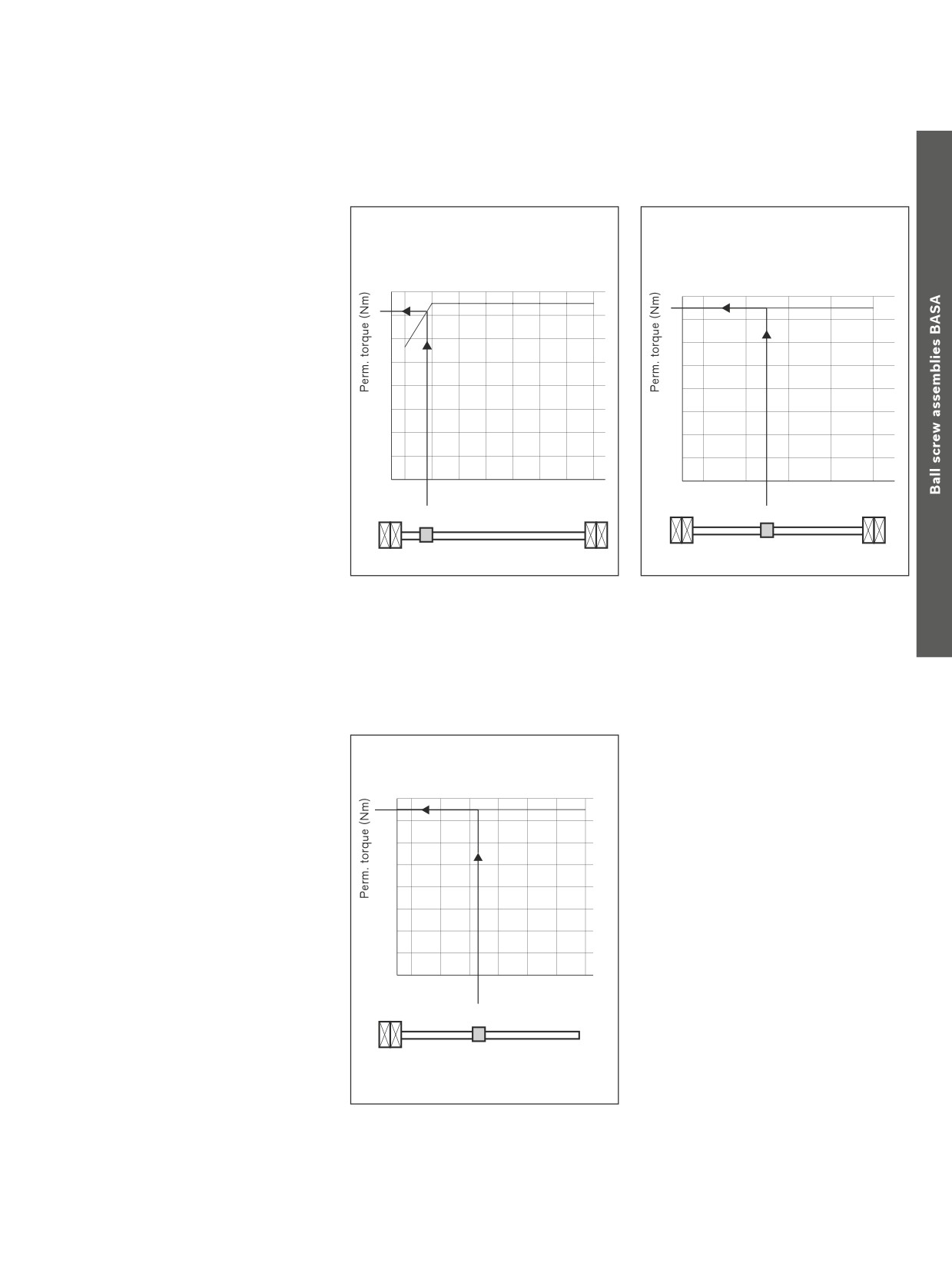
The influencing variables below limit
Buckling load
the permissible drive torque with the
End fixity:
Coefficient fFc
driven nut
1000
80
Nut fixed
Nut floating
800
63
--
Screw length
A - A
600
500
-–
Screw diameter
50
F
F
400
lc
300
-–
End fixity
40
A - B
200
-–
Stretching force
32
F
F
End fixity I
End fixity IV
lc
40.6
20.4
-–
Geometry of the screw end
25
A - C
10090
-–
Load direction; in an unfavorable case,
80
F
F
70
20
60
a compressive force on the longer screw
lc
50
40
section (buckling load)
B - B
16
30
F
F
End fixity II / IV
End fixity V
12
lc
20
20.4
10.2
A - C
10
9
8
F
End fixity III / VI
8
F
7
lc
2.6
6
5
A - C
4
6
F
F
3
End fixity VI
lc
2
2.6
1,0
0,9
0,8
0,7
End fixity
0,6
fFc value
0,5
100
500
1000
5000
10000
2.6
III / VI
100
200
500
1000
5000
10000
10.2
V
200
500
1000
5000
10000
20.4
II / IV
40.6
I
200
500
1000
5000
10000
Length lc (mm)
4
The length and diameter of the screw and
d2
Fc
= Theoretically permissible
Fc
= fFc
2
· 104 (N)
its end fixity are taken into account by the
axial load on screw
(N)
l
k
Euler buckling case.
Fcp
= Permissible axial load on screw
Fk
This yields the permissible axial load on
Fcp
=
(N)
during operation
(N)
2
the screw (see the diagram above). In
fFc
= Corrector value determined by
practice, the adjacent formulas are used for
FL
≤ Fcp
bearing
calculation.
d2
= For root diameter of screw, see
dimension tables
(mm)
lc
= unsupported thread length
(mm)
With a stretched screw, the following
Fc
FL
= operating load of the customer
(N)
Fcp
=
+ Fst
applies:
2
Fst
= stretching force of the screw
(N)
Due to an increase in temperature, the stretching force may be reduced. You must take this
effect into account when calculating Fkperm.
The drive torque that is necessary for the
FL P
Mta
= drive torque on the nut
(Nm)
Mta
operating load results from the following
2 000
π η
F
= operating load
(N)
formula:
P
= lead
(mm)
The dynamic drag torque must be taken
η
= mechanical efficiency
(approx. 0.9)
into account for preloaded nut units.
Mta ≤ MP
MP = permissible torque at the
screw journal
(Nm)
BASA size
MScperm (Nm)
Recommended maximum torque with
32
< 40
the geometry of screw end 51
51
40
< 150
50
< 180
63
< 190
175
Calculation and examples
Typical applications
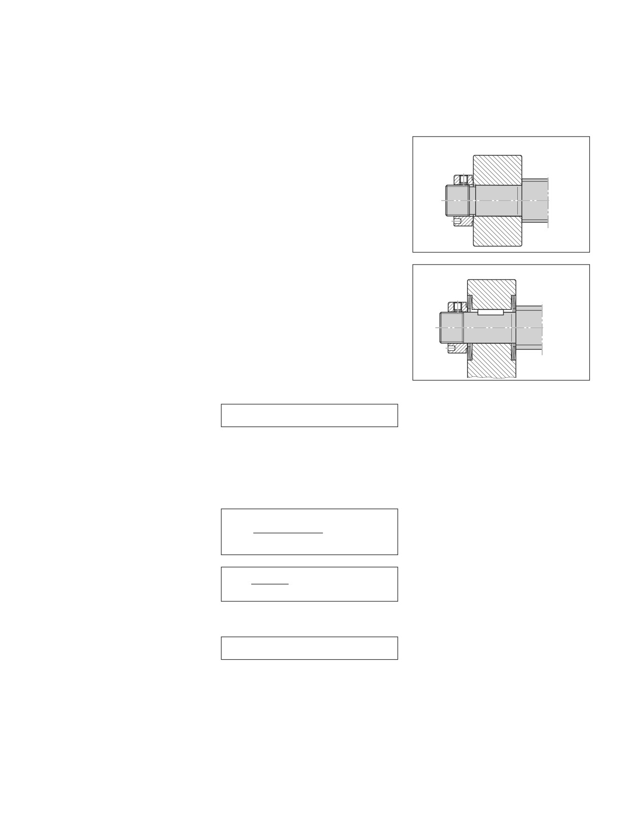
Example: A long screw axis, e.g. in the case
Example: A short screw with a machine
End fixity I fixed-fixed:
of water jet cutting, makes possible high drive
tool axis makes possible high drive torque
Parameters:
torque on a nut position-dependent basis
regardless of the nut position
--
Screw length; two cases
-–
Screw diameter
-–
End fixity in this case, fixed-fixed:
160
160
--
Stretching force ignored
140
140
(see the next page)
--
Geometry of screw end Form 51 on
120
120
two sides
100
100
--
Load direction in an unfavorable case, a
80
80
compressive force on the longer screw
60
60
section
40
40
20
20
0
0
500
1500
2500
3500
4500
5500
6500
7500
500
1000
1500
2000
2500
Lmax
Lmax
Nut position (mm)
Nut position (mm)
F
F
End fixity II fixed-floating:
Stretching is not possible.
End fixity III floating-floating
This type of end fixity is virtually never used.
End fixity IV fixed-free
Example: A short screw in a press applica-
Parameters:
tion, for example, makes possible high levels
--
Screw length
of torque
-–
Screw diameter
-–
End fixity, here fixed-free
160
-–
Stretching force, none
140
--
Geometry of screw end Form 51 on
120
one side
100
-–
Compressive load toward fixed bearing
80
60
40
20
0
200
400
600
800
1000
1200
1400
Lma
Nut position (mm)
F
176
Screw Assemblies | Ball Screw Assemblies BASA
Calculation and examples
Design of drive unit FAR-B-S
Stretching screws
Basic principles
Fixed mounting
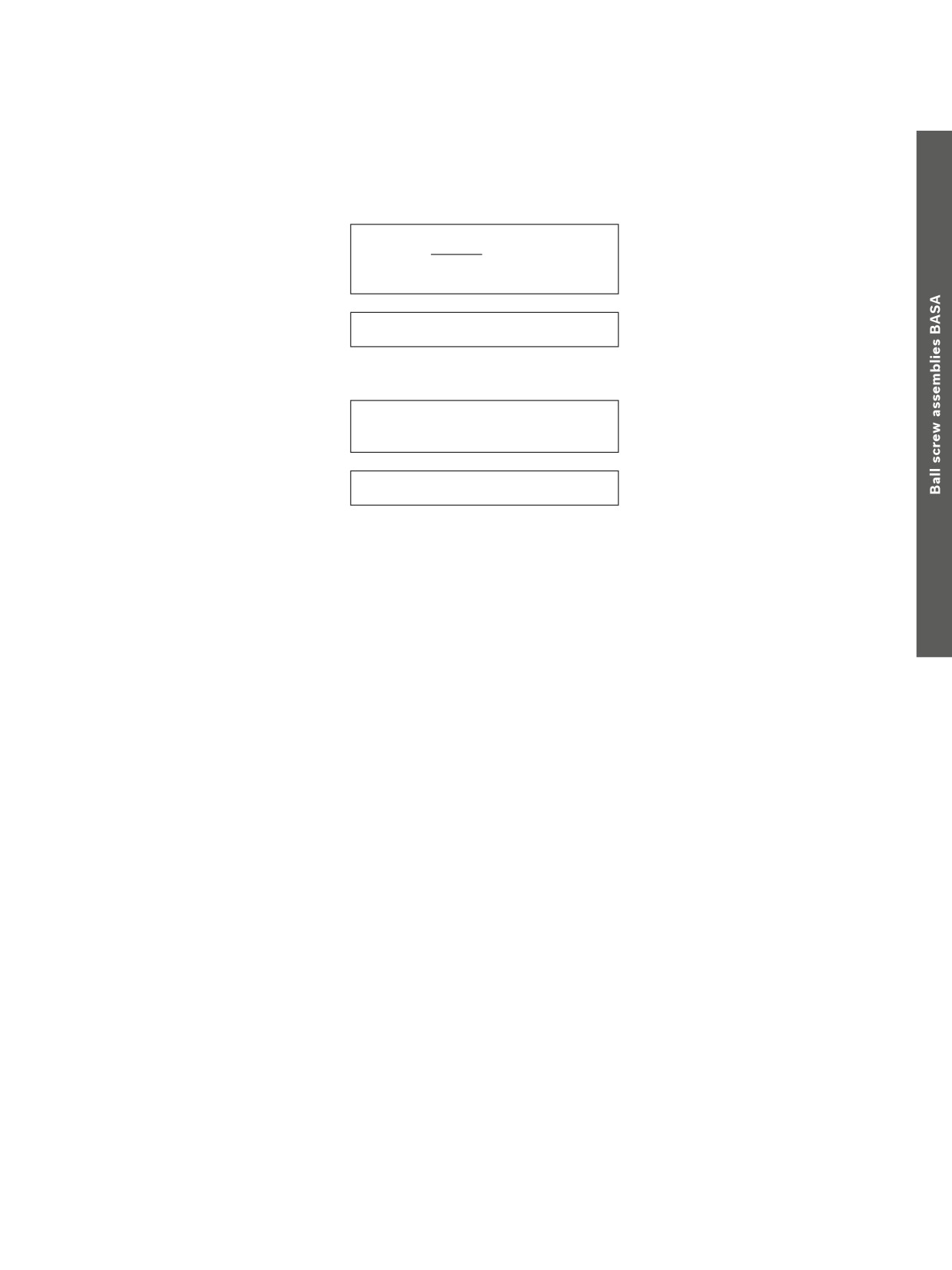
To be able to exploit the efficiency of a
The change in length and the tensile stress
system with a driven nut to the full, it is
that results due to stretching must be kept
advisable to use the type of end fixity with
to a range that is acceptable for the overall
fixing of the screw on two sides (fixed-fixed).
system. Otherwise, elastic deformation
Stretching of the screw has the following
can lead to impermissible lead deviations
positive effect on the overall system:
between the nut and the screw, which can
--
Compensation of temperature effects to
negatively impact the service life.
avoid compressive loads in the screw,
In the case of convection cooling of the
which reduces the risk of buckling
screw, stretching can maintain a maximum
temperature difference of about 10 °C.
With long, composite screws, temperature
Mounting with cup spring
compensation of 5 °C is sensible. Water
cooling of the screw is necessary at higher
temperature differences.
Linear expansion
Calculation of the linear expansion of a
∆L = Lthr · αL · (|s - |r)
∆L
= linear expansion
(mm)
screw in operation with a temperature
Lthr
= thread length
(mm)
increase.
αL
= linear expansion coefficient
(1/K)
Where αL = 0.0000115
|s
= Screw temperature
in operation
(K)
|r
= room temperature
(K)
Stretching force
Calculation of the stretching force that is
π
Fst
= stretching force
(N)
∆L · E ·
· dap2
needed for compensating the linear
4
dap
= approximation diameter
(mm)
Fst =
expansion.
Lthr
E
= Young's modulus
(N/mm2)
d0 + d2
d0
= nominal diameter
(mm)
dap =
d2
= screw core diameter
(mm)
2
Compressive stress
The compressive stress in the screw that
σc = E · (|s - |r) · αL
σc
= compressive stress due
occurs in the case of fixed mounting on two
to increased temperature
(N/mm2)
sides is calculated as shown.
Where E = 210,000 N/mm2
177
Calculation and examples
Tensile stress
For operation, the tensile stress in the
Tensile stress due to stretching that is generated in the screw
screw due to stretching must be greater
than the compressive force due to tempera-
σt
= tensile stress
(N/mm2)
Fst
ture. At the same time, the permissible
σt =
π
· dap2
tensile stress must not be exceeded.
4
σt
< σp
The maximum permissible tension
σp = 70 N/mm2
Permissible change in length
Stretching results in a change of length of
∆Lperm = perm. linear expansion
(mm)
∆Lperm = Lthr · 0.0001
the screw, which causes a change in the
Lthr
= thread length
(mm)
geometry of the screw and the raceway
geometry. To avoid negative effects on the
service life of the Ball Screw Assembly, you
∆L ≤ ∆Lperm
must check it.
178
Screw Assemblies | Ball Screw Assemblies BASA
End Bearings
Design notes, installation
Bearing design
Screw end
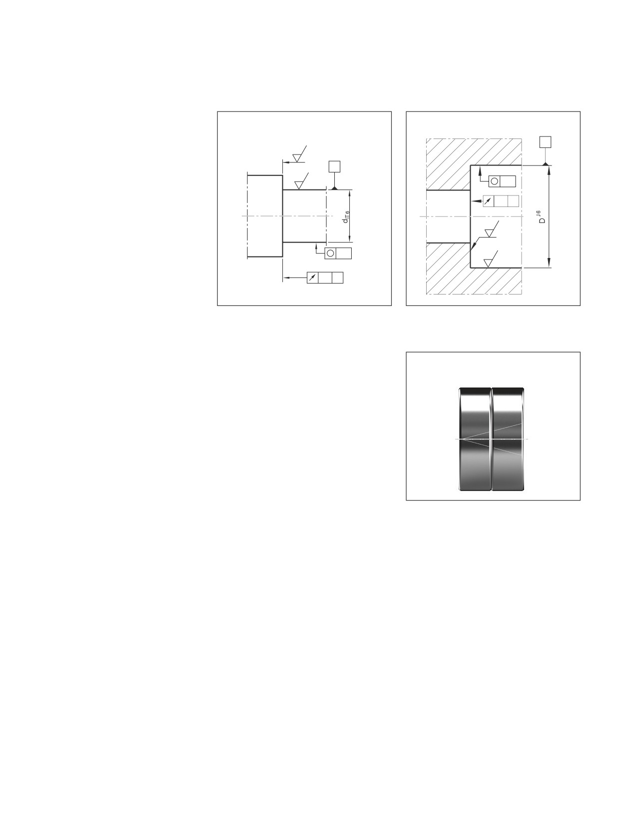
Housing
For customer machining, please consider
the design notes for screw ends and
C
0,8
housings.
For Rexroth screw end designs, see
A
“End Machining Details.”
0,8
IT4
Rexroth delivers complete drive systems
including bearing units without housing.
IT5
C
Calculations are performed with the
formulas used in the antifriction bearing
1,6
industry.
IT3
1,6
IT4
A
Mounting
Angular-contact thrust ball bearings and deep-groove ball bearings
Outer raceway markings for paired
When mounting the angular-contact thrust ball bearings LGF and LGN, ensure that the
bearings
mounting forces are exerted only on the bearing rings. Never apply mounting forces via the
anti-friction bearing elements or the seal rings! The two sections of the inner raceway may
not be separated during assembly or disassembly for any reason!
Tighten the mounting screws for screw-down or flange-mounted bearings in crosswise
sequence. The mounting screws may be subjected only to tension amounting to a maximum
of 70% of their yielding point.
The screw-down (LGF) bearings have a groove on the cylindrical surface of the outer
raceway for disassembly. The individual bearings of the bearing pair series LGF-C... and
LGN-C... are marked on the cylindrical surfaces of the outer raceways (see Figure). The
markings reveal the bearing sequence. The sealing rings should face outwards after proper
mounting.
Slotted nut NMA, NMZ
The bearings are preloaded by tightening the nuts.
In order to prevent settling phenomena, we recommend first tightening the slotted nut by twice the value of the tightening torque MA and
then easing the load. Only then should the slotted nut be retightened to the specified tightening torque MA.
The two set screws are then alternately tightened using a hexagon socket wrench.
The components are disassembled in the reverse order, i.e. the set screws have to be removed before the slotted nut.
The slotted nuts can be used several times when properly assembled and disassembled by competent personnel. The inner raceways of
the bearings are dimensioned in such a way as to achieve a defined bearing preload sufficient for most applications when the slotted nut is
tightened (MA in accordance with Dimension Table).
179
End Bearings
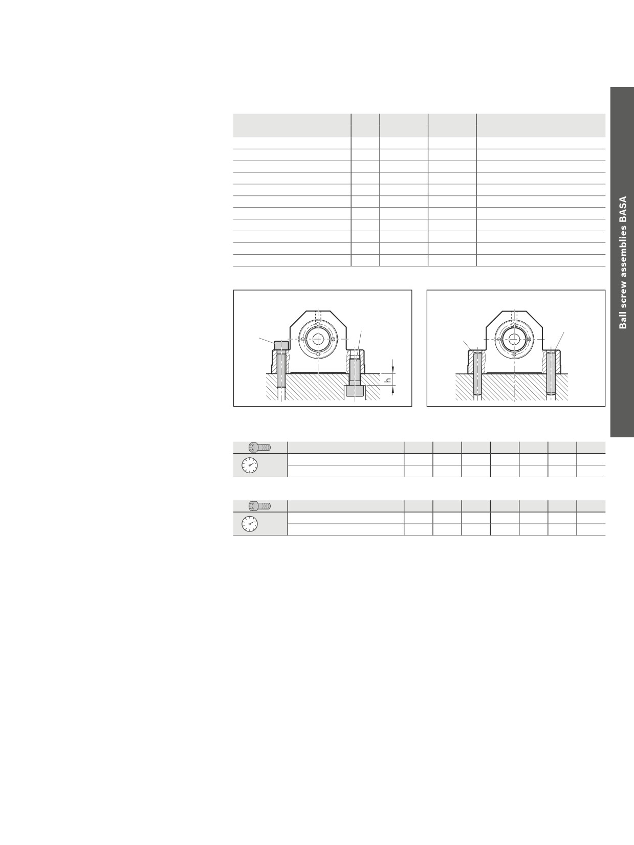
Mounting the housing
Size
h
O1
O2
O3, tapered pin (hardened)
Housing mounting SEB
d0xP
(mm)
DIN 912
DIN 912
O4, straight pin (DIN 6325)
Tighten the fastening screws of the pillow-
6x1/2
8
M5x20
M6x16
4x20
block bearings in a crosswise sequence.
8x1/2/2,5/5
8
M5x20
M6x16
4x20
Refer to the table for the maximum tight-
12x2/5/10
8
M5x20
M6x16
4x20
ening torque. The threaded ring fixes the
16x5/10/16
11
M8x35
M10x25
8x40
complete bearing in the housing. Use
20x5/10/20/40
11
M8x35
M10x25
8x40
threadlocking adhesive when assembling
25x5/10/25
14
M10x40
M12x30
10x50
the threaded ring.
32x5/10/20/32/64
14
M10x40
M12x30
10x50
40x5/10/12/16/20/25/30/40
16
M12x50
M14x35
10x50
50x5/10/12/16/20/25/30/40
16
M12x55
M14x35
10x60
cc
Align the screw with nut, the bear-
63x10/20/40
16
M12x65
M14x35
10x70
ings and the guide such that they are
80x10/20
22
M16x70
M20x50
12x80
completely flush with one another. The
Rexroth gauge is suitable as an aid.
Tightening
Locating pins
O2
O4
O1
O3
Steel/steel material pairing
Tightening torques for fastening screws
Strength class for O1; O2
M5
M6
M8
M10
M12
M14
M20
according to VDI 2230
8.8
5.5
9.5
23
46
80
125
390
where mG = mK = 0.125 (friction coefficient)
(Nm)
12.9
9.5
16.0
39
77
135
215
650
Steel/aluminum and aluminum/ aluminum material pairings
Strength class for O1; O2
M5
M6
M8
M10
M12
M14
M20
8.8
4.8
8.5
20
41
70
110
345
(Nm)
12.9
4.8
8.5
20
41
70
110
345
Mounting screws
cc
Always make sure the screws
are secure where there are high screw
loads!