Rexroth: Screw Assemblies. Catalog (R999001185/2020-03) - page 9
120
Screw Assemblies | Ball Screw Assemblies BASA
Accessories
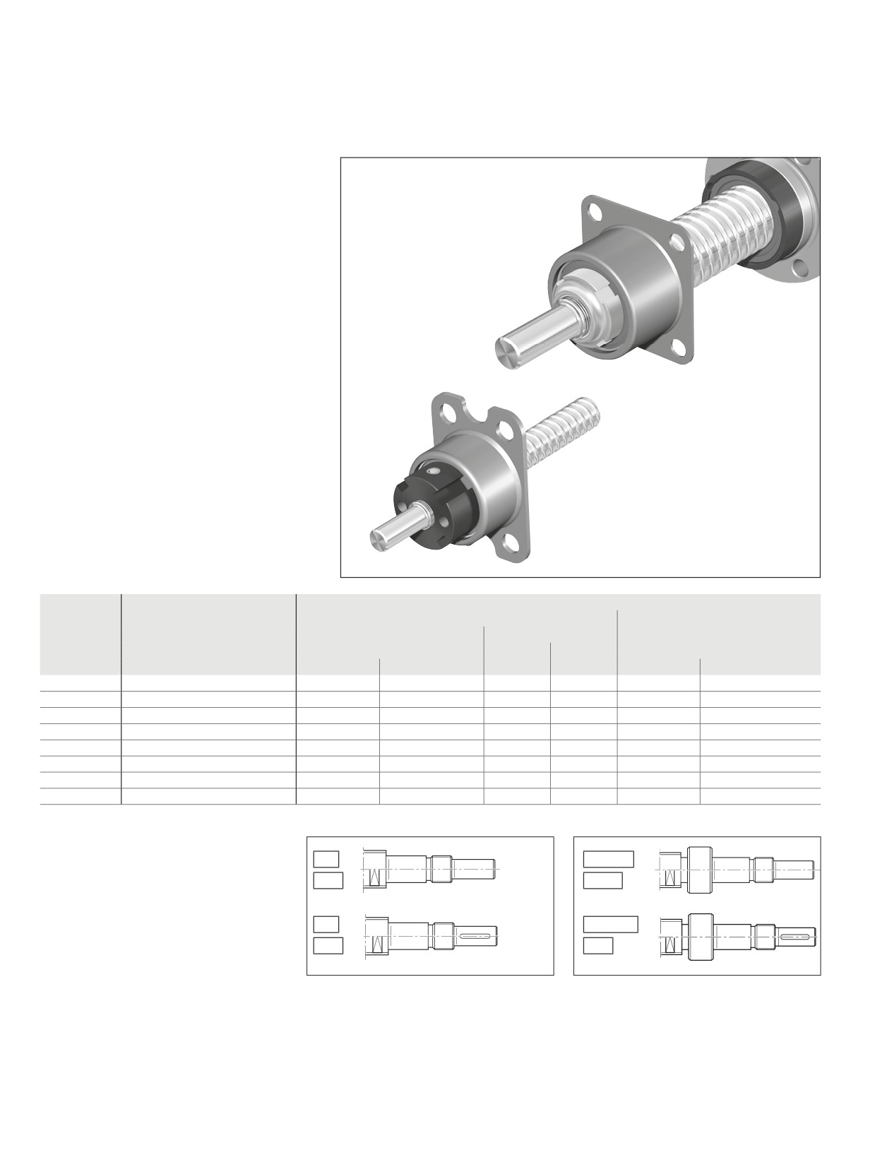
Bearing assembly LAL
Fixed bearing with angular-
contact thrust ball bearing LGL
Double-thrust, screw-down, for inexpensive
designs
The fixed bearing consists of:
--
Angular-contact thrust ball bearing LGL
-–
Slotted nut NMG..., NMZ...
Separate technical dimensioning to
determine the limit values is absolutely
necessary for all attachments (e.g. pillow
block units, bearing assembly, etc.)
Size
Module
Single parts
Angular-contact thrust ball bearing unit
Slotted nut
Load ratings1)
dyn. C
stat. C0
d0x P
Part number
Abbreviation
Part number
(N)
(N)
Abbreviation
Part number
6 x 1/2
R1590 406 00
LGL-D-0624
R3414 038 06
1,340
1,250
NMZ 6x0.5
R3446 001 04
8 x 1/2/2.5/5
R1590 406 00
LGL-D-0624
R3414 038 06
1,340
1,250
NMZ 6x0.5
R3446 001 04
12 x 2/5/10
R1590 406 00
LGL-D-0624
R3414 038 06
1,340
1,250
NMZ 6x0.5
R3446 001 04
12 x 5/10
R1590 412 00
LGL-A-1244
R3414 040 06
13,200
17,900
NMG 12x1
R3446 002 02
16 x 5/10
R1590 412 00
LGL-A-1244
R3414 040 06
13,200
17,900
NMG 12x1
R3446 002 02
20 x 5
R1590 412 00
LGL-A-1244
R3414 040 06
13,200
17,900
NMG 12x1
R3446 002 02
25 x 5/10
R1590 415 00
LGL-A-1547
R3414 041 06
16,400
22,400
NMG 15x1
R3446 011 02
32 x 5/10
R1590 420 00
LGL-A-2060
R3414 042 06
27,500
40,000
NMG 20x1
R3446 005 02
1) See page 181 for load on bearing
Suitable for screw ends: Form
81
831/83
81A
83A
82
841/84
82A
84A
Ball Screw Assemblies
BASA |
121
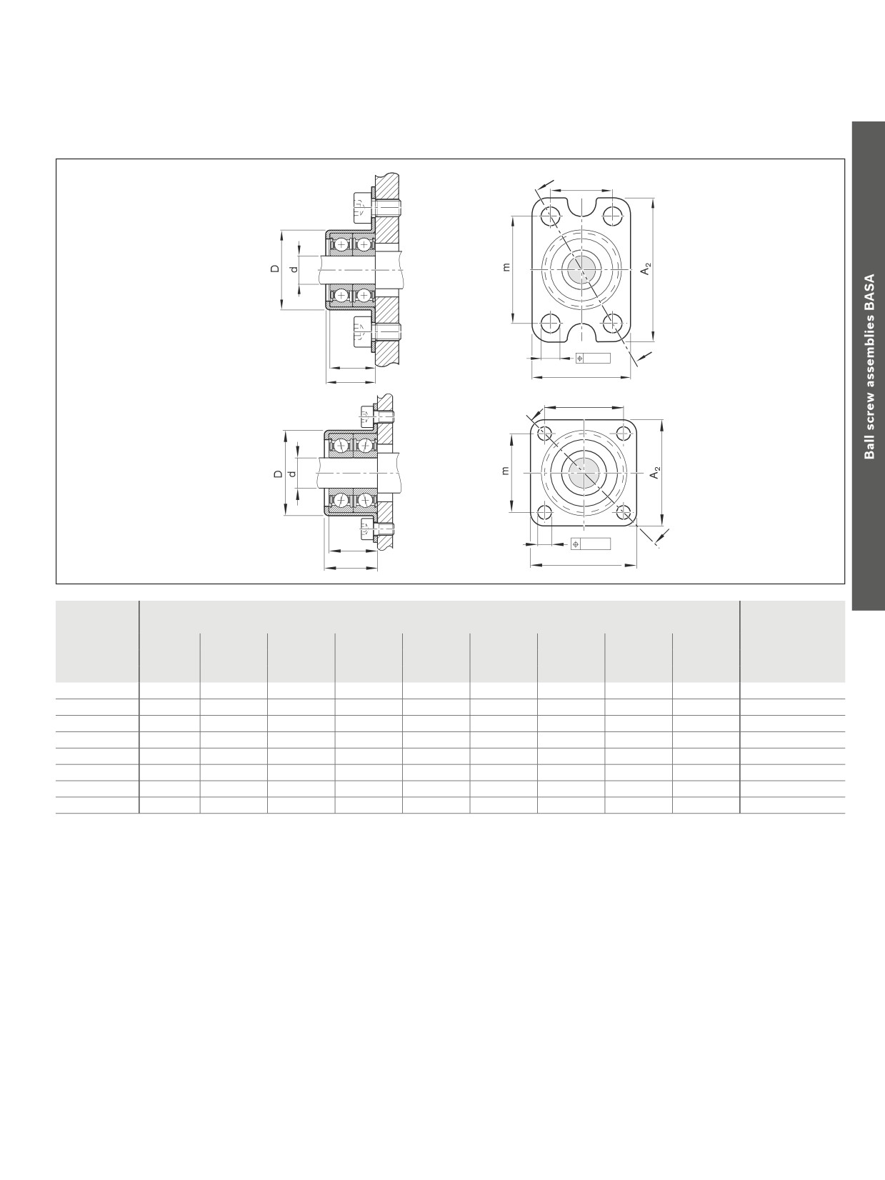
Accessories
n
d2
B
Ø 0,2
A1
H
n
d2
B
Ø 0,2
A1
H
Size
(mm)
Weight of bearing
d
D
A1)
A2
n
m
H
B
d2
+0.03
d0x P
-0.01
-0.25
(kg)
6 x 1/2
6
20.50
24
35
15
26
13
12
4.5
0,023
8 x 1/2/2.5/5
6
20.50
24
35
15
26
13
12
4.5
0,023
12 x 2/5/10
6
20.50
24
35
15
26
13
12
4.5
0,023
12 x 5/10
12
35.45
44
50
32
38
22
20
6.6
0,120
16 x 5/10
12
35.45
44
50
32
38
22
20
6.6
0,120
20 x 5
12
35.45
44
50
32
38
22
20
6.6
0,120
25 x 5/10
15
38.45
47
51
35
39
24
22
6.6
0,140
32 x 5/10
20
50.45
60
60
47
47
30
28
6.6
0,300
122
Screw Assemblies | Ball Screw Assemblies BASA
Accessories
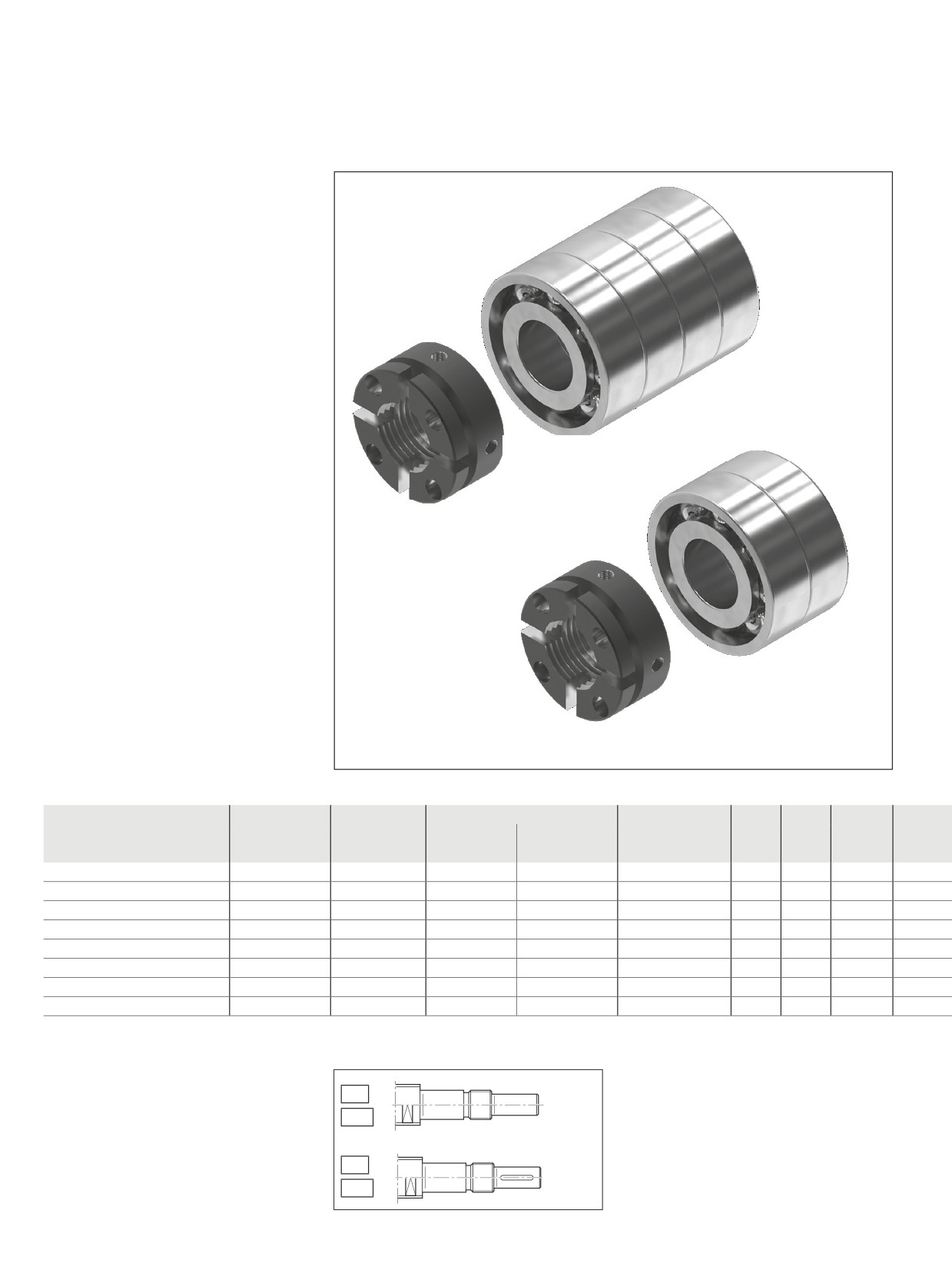
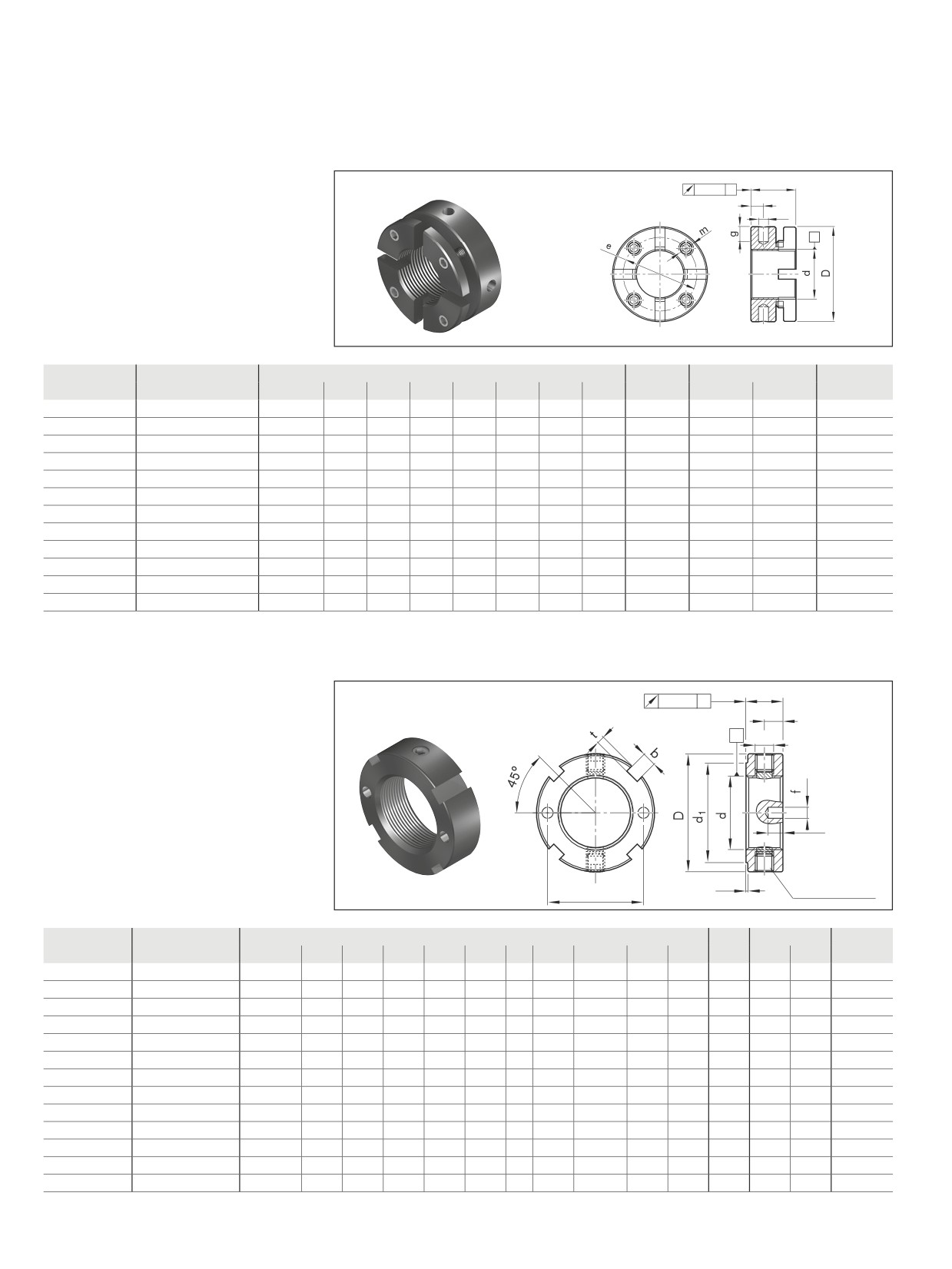
Bearing assembly LAS
Fixed bearing with angular-contact
thrust ball bearing LGS
Double-thrust, series LAS-E
The fixed bearing consists of:
--
Angular-contact ball bearing LGS as per
DIN 628. Not available as a separate
part.
--
Slotted Nut NMA
Separate technical dimensioning to
determine the limit values is absolutely
necessary for all attachments (e.g. Pillow
1)
Block Units, assembly group Bearing
Unit, etc.).
Size
LAS
LGS
Slotted nut
Weight complete
C
C0
nG 1)
d0 x P
Part number
Abbreviation
Abbreviation
Part number
m
(kg)
(kN)
(kN)
(min-1)
16 x 5/10/16
R159A 410 01
LGS-E-1030
NMZ 10x1
R3446 002 04
0.13
20
25.8
13,500
20 x 5/10/20/40
R159A 412 01
LGS-E-1232
NMZ 12x1
R3446 003 04
0.16
21.7
29.2
11,700
25 x 5/10/25 2)
R159A 417 01
LGS-E-1747
NMA 17x1
R3446 014 04
0.29
27.9
31.9
8,550
32 x 5/10/20/32/64
R159A 420 01
LGS-E-2047
NMA 20x1
R3446 015 04
0.57
39.9
63.8
8,550
40 x 5/10/12/16/20/25/30/40
R159A 430 01
LGS-E-3072
NMA 30x1.5
R3446 016 04
1.68
98.3
163.1
5,850
50 x 5/10/12/16/20/25/30/40
R159A 435 01
LGS-E-3580
NMA 35x1.5
R3446 012 04
2.19
111.2
188.5
4,950
63 x 10/20/40
R159A 440 01
LGS-E-4090
NMA 40x1.5
R3446 016 08
2.74
140.8
257.7
4,500
80 x 10/20
R159A 450 01
LGS-E-50110
NMA 50x1.5
R3446 019 04
4.95
211.2
392.3
3,600
1) Values as a guide for low bearing load, good heat dissipation and suitable lubricating greases with low consistency
2) Version 1+1
Suitable for screw ends: Form
81
81A
82
82A
123
Accessories
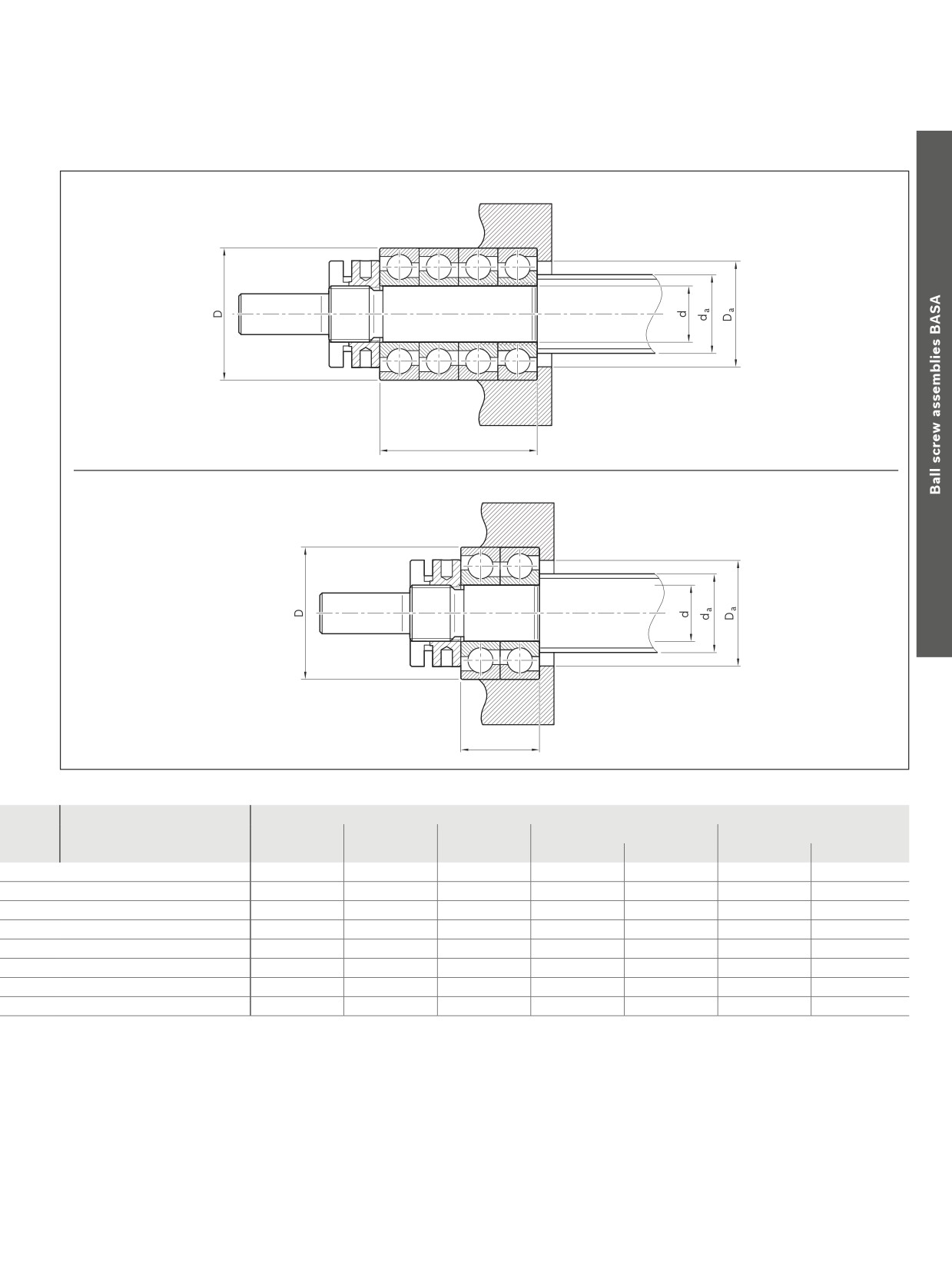
B
1)
B
d0 x P
(mm)
d
D
B
Da
da
min.
max.
min.
max.
16 x 5/10/16
10 -0.008
30 -0.009
36
22.9
25.8
14.2
22.0
20 x 5/10/20/40
12 -0.008
32 -0.011
40
25.0
27.8
16.2
24.0
25 x 5/10/25
17 -0.008
47 -0.011
28
36.2
41.4
22.6
35.0
32 x 5/10/20/32/64
20 -0.010
47 -0.011
56
36.0
41.0
25.6
35.0
40 x 5/10/12/16/20/25/30/40
30 -0.010
72 -0.013
76
56.5
65.0
37.0
55.5
50 x 5/10/12/16/20/25/30/40
35 -0.012
80 -0.013
84
63.0
71.0
44.0
62.0
63 x 10/20/40
40 -0.012
90 -0.015
92
72.0
81.0
49.0
71.0
80 x 10/20
50 -0.012
110 -0.015
108
89.0
100.0
61.0
88.0
124
Screw Assemblies | Ball Screw Assemblies BASA
Accessories
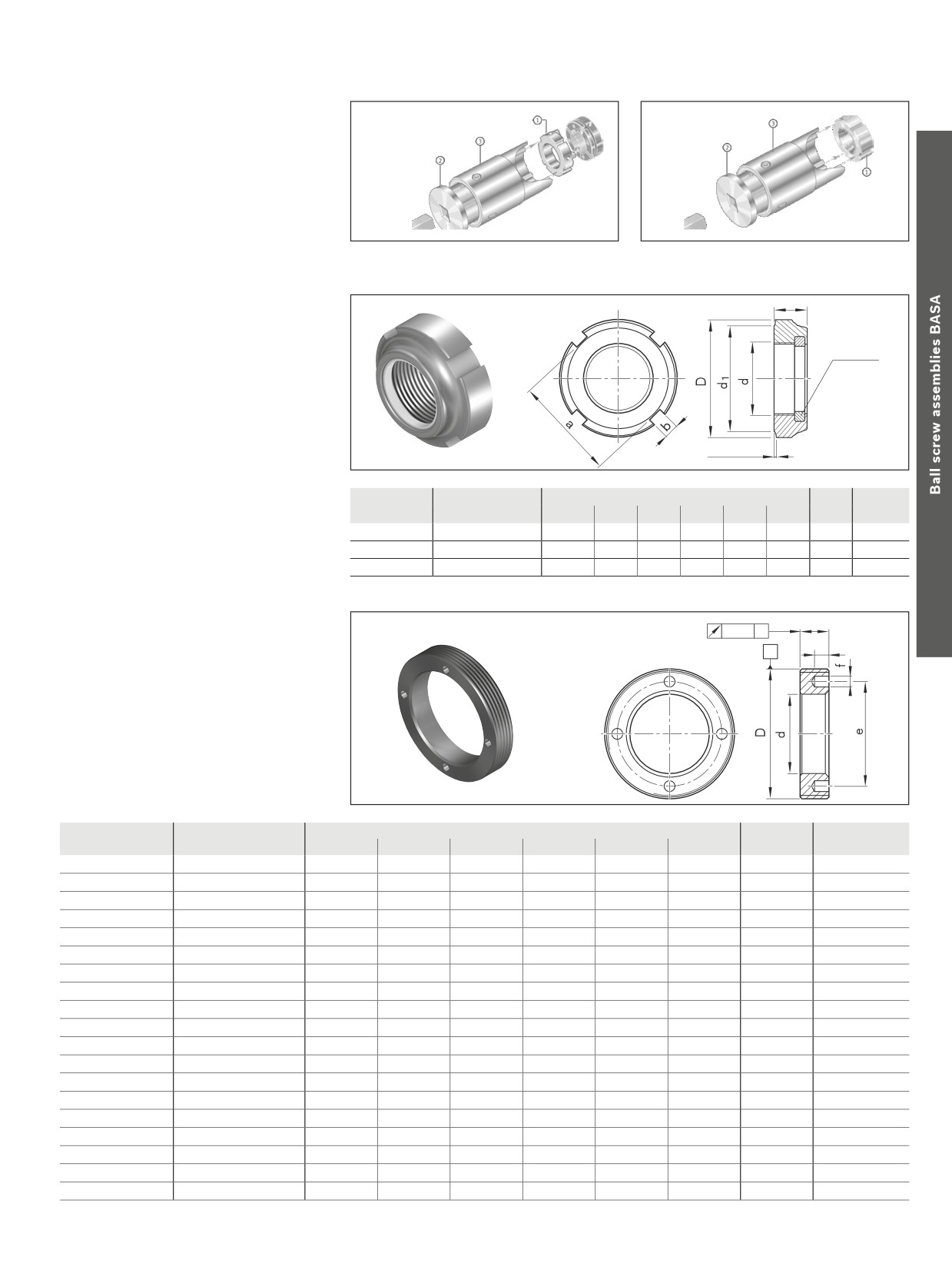
Slotted Nuts NMA, NMZ and NMG for fixed bearings
Slotted nut NMA
B
0,005
A
c
f
--
For maximum vibratory loads
--
For new designs
A
MA = tightening torque for slotted nut
FaB = axial breaking load of slotted nut
MAG= tightening torque for set screw
Abbreviation
Part number
(mm)
MA
FaB
MAG
Mass
d
D
B
c
m
e
f
g
(Nm)
(kN)
(Nm)
(g)
NMA 15x1
R3446 020 04
M15x1
30
18
5
M5
24
4
5
10
100
3
60
NMA 17x1
R3446 014 04
M17x1
32
18
5
M5
26
4
5
15
120
3
70
NMA 20x1
R3446 015 04
M20x1
38
18
5
M6
31
4
6
18
145
5
130
NMA 25x1.5
R3446 011 04
M25x1.5
45
20
6
M6
38
5
6
25
205
5
160
NMA 30x1.5
R3446 016 04
M30x1.5
52
20
6
M6
45
5
7
32
250
5
200
NMA 35x1.5
R3446 012 04
M35x1.5
58
20
6
M6
51
5
7
40
280
5
230
NMA 40x1.5
R3446 018 04
M40x1.5
65
22
6
M6
58
6
8
55
350
5
300
NMA 45x1.5
R9130 342 15
M45x1.5
70
22
6
M6
63
6
8
65
360
5
340
NMA 50x1.5
R3446 019 04
M50x1.5
75
25
8
M6
68
6
8
85
450
5
430
NMA 60x2
R9130 342 16
M60x2.0
90
26
8
M8
80
6
8
100
550
15
650
NMA 70x2
R9130 342 17
M70x2.0
100
28
9
M8
90
8
10
130
650
15
790
NMA 90x2
R9163 113 51
M90x2.0
130
32
13
M10
118
8
10
200
900
20
1,530
NMA 15 to NAM 40 with 4 segments
NMA 45 to NAM 90 with 6 segments
Slotted nut NMZ
B
0,005
A
c
-–
For existing designs
A
m
--
For timing belt side drive
-–
For driven nuts
g
MA = tightening torque for slotted nut
0,5
FaB = axial breaking load of slotted nut
e
Set screw
MAG= tightening torque for set screw
Abbreviation
Part number
(mm)
MA
FaB MAG
Mass
d
D
B
d1
c
m
b
t
e
f
g
(Nm)
(kN)
(Nm)
(g)
NMZ 6x0.5
R3446 001 04
M6x0.5
16
8
12
4
M4
3
2.0
11.0
2.5
3.5
2
17
1
10
NMZ 10x1
R3446 002 04
M10x1
18
8
14
4
M4
3
2.0
14.0
2.5
3.5
6
31
1
10
NMZ 12x1
R3446 003 04
M12x1
22
8
18
4
M4
3
2.0
17.0
2.5
3.5
8
38
1
15
NMZ 17x1
R3446 004 04
M17x1
28
10
23
5
M5
4
2.0
22.5
3.0
4.0
15
57
3
28
NMA 20x1
R3446 005 04
M20x1
32
10
27
5
M5
4
2.0
26.0
3.0
4.0
18
69
3
35
NMZ 25x1.5
R3446 007 04
M25x1.5
45
20
40
10
M6
5
2.0
35.0
4.0
5.0
25
211
5
55
NMA 30x1.5
R3446 006 04
M30x1.5
45
12
40
6
M6
5
2.0
37.5
4.0
5.0
32
112
5
75
NMZ 45x1.5
R3446 032 04
M45x1.5
65
14
59
7
M6
6
2.5
-
-
-
65
181
5
170
NMZ 55x2
R3446 033 04
M55x2
75
16
68
8
M6
7
3.0
-
-
-
95
229
5
230
NMZ 60x2
R3446 031 04
M60x2
80
16
73
8
M6
7
3.0
-
-
-
100
255
5
250
NMZ 70x2
R3446 034 04
M70x2
92
18
85
9
M8
8
3.5
-
-
-
130
305
15
360
NMZ 80x2
R3446 035 04
M80x2
105
18
95
9
M8
8
3.5
-
-
-
160
355
15
460
NMZ 90x2
R3446 036 04
M90x2
120
20
108
10
M8
10
4.0
-
-
-
200
410
15
700
125
Accessories
Assembly tool for
slotted nut
General-purpose socket wrench insert for
slotted nuts NMA / NMZ
--
Available on request
NMA: consisting of components:
NMZ: consisting of components: ZMS
AMS, ZMS and ZME
and ZME
B
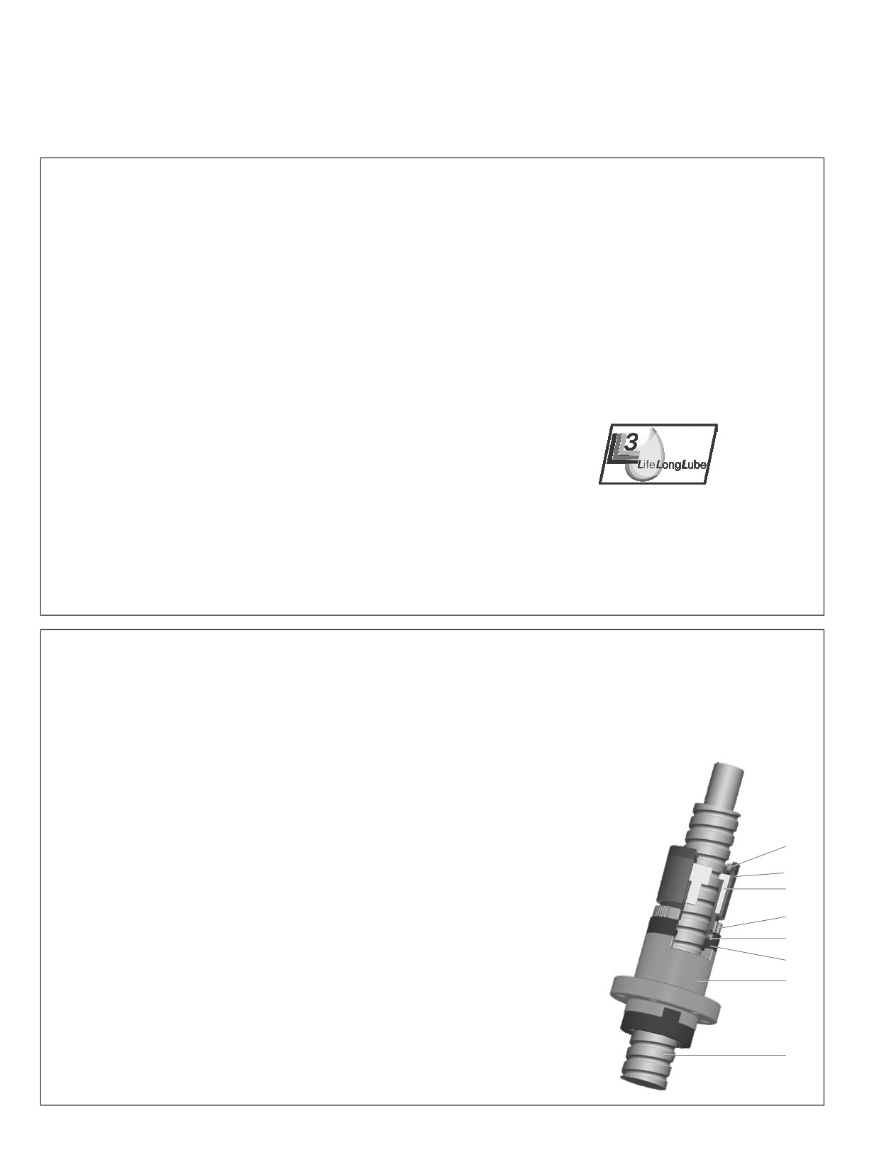
Slotted nut NMG
--
For inexpensive designs
Polyamide
insert
min. 0.3
Abbreviation
Part number
Dimensions (mm)
MA
Mass
d
D
B
d1
a
b
(Nm)
(g)
NMG 12x1
R3446 002 02
M12x1
21
7.6
18
18
3
8
10
NMG 15x1
R3446 011 02
M15x1
24
8.6
21
21
4
10
13
NMG 20x1
R3446 005 02
M20x1
32
9.6
27
27
4
18
24
MA = tightening torque for slotted nut
B
0,01
A
Ring nut GWR
g
A
--
For angular-contact thrust ball bearing LGN
--
For cylindrical single nut ZEM-E-S
Attention:
Use a threadlocker (for example,
Loctite 638) to secure against loosening
MA = tightening torque for housing nut
Abbreviation
Part number
Dimensions (mm)
MA
Mass
D
d
B
e
f
g
(Nm)
(g)
GWR 18x1
R1507 040 33
M18x1
8.5
8
12.5
2.5
3
6
10.0
GWR 23x1
R1507 240 35
M23x1
13.0
8
18.0
2.5
3
8
15.0
GWR 26x1.5
R1507 240 22
M26x1.5
16.5
8
20.5
2.5
3
10
16.5
GWR 30x1.5
R1507 340 34
M30x1.5
17.0
8
23.0
3.0
4
20
29.0
GWR 36x1.5
R1507 040 23
M36x1.5
22.0
8
29.0
3.0
4
25
35.0
GWR 40x1.5
R1507 140 03
M40x1.5
25.0
8
33.0
3.0
4
28
39.5
GWR 45x1.5
R1507 240 04
M45x1.5
28.0
8
38.0
3.0
4
30
55.0
GWR 50x1.5
R1507 240 25
M50x1.5
31.0
10
40.0
4.0
5
45
86.0
GWR 55x1.5
R1507 340 05
M55x1.5
36.0
10
46.0
4.0
5
50
96.0
GWR 58x1.5
R1507 440 32
M58x1.5
43.0
10
50.0
4.0
5
58
84.0
GWR 60x1
R1507 440 28
M60x1
43.0
10
51.0
4.0
5
60
97.0
GWR 62x1.5
R1507 440 29
M62x1.5
43.0
12
53.0
5.0
6
60
127.0
GWR 65x1.5
R1507 440 26
M65x1.5
47.0
12
55.0
4.0
5
70
136.0
GWR 70x1.5
R1507 440 06
M70x1.5
42.0
12
58.0
4.0
5
75
216.0
GWR 78x2
R1507 567 27
M78x2
54.0
15
67.0
6.0
7
90
286.0
GWR 92x2
R1507 640 09
M92x2
65.0
16
82.0
6.0
7
125
385.0
GWR 95x2
R1507 667 28
M95x2
68.0
16
82.0
6.0
7
130
425.0
GWR 112x2
R1507 740 11
M112x2
82.0
18
100.0
8.0
8
175
596.0
GWR 115x2
R1507 767 29
M115x2
85.0
18
100.0
8.0
8
200
664.0
126
Screw Assemblies | Ball Screw Assemblies BASA
Accessories
Ball Screw Assembly with front lube unit
Characteristic features
Further highlights
Equipped with Rexroth’s functionally reliable, series-made front
--
Delivered with the Ball Screw Assembly ready-mounted.
lube unit, a Ball Screw Assembly can attain an exceptionally long
-–
Attaches to one side of the nut, thus saving space.
travel life without relubrication. Thanks to intensive development
-–
Can be used in all mounting positions, both in horizontal and
work and thorough testing under realistic conditions, the use of
vertical installations.
front lube units combined with prelubricated nuts enables you
--
Available for almost all nut types with diameters 20 to 40
to achieve lifelong, optimal lubrication of Rexroth precision Ball
-–
Easy to integrate in constructions by attaching it either on the
Screw Assemblies.
flange side or on the opposite side of the single-start nuts.
From its built-in oil reservoir, the front lube unit delivers the precise
--
When attached to both sides, it also meets the lubrication
amount of oil required to replenish the used amounts of oil in the
needs of high-capacity two-start nuts (FED-E-B).
soap matrix of the grease. The oil is applied directly to the raceway
--
Can be used in all normal ambient conditions, except in wet or
of the ball screws via the low-friction point-contact zone of the
dusty environments.
open-pored foam. This optimized delivery minimizes lubricant
consumption and allows you to achieve lifelong lubrication.
Ecologically sound
The front lube unit ideally combines eco-friendliness with cost-
efficiency. It minimizes oil consumption and keeps the surround-
ings clean. This helps to conserve resources.
Lubrication concept
This logo indicates that the Rexroth Ball Screw Assembly with
prelubed nut and front lube unit are lubed for life.
Note: The front lube unit is not suitable for use with driven nuts.
Lifelong lubrication
The effective life of the Rexroth front lube unit matches the service life curve of the Ball Screw
Assembly. When operated within the recommended load limits, a Ball Screw Assembly equipped with
a Front Lube Unit will require no relubrication, thanks to the optimal delivery of lubricant. Based on our
extensive tests, the lubrication performance of the front lube unit can now be reliably predicted for the
first time. With a Front Lube Unit from Rexroth, a Ball Screw Assembly can run trouble-free for
five years or 300 million revolutions without any relubrication.
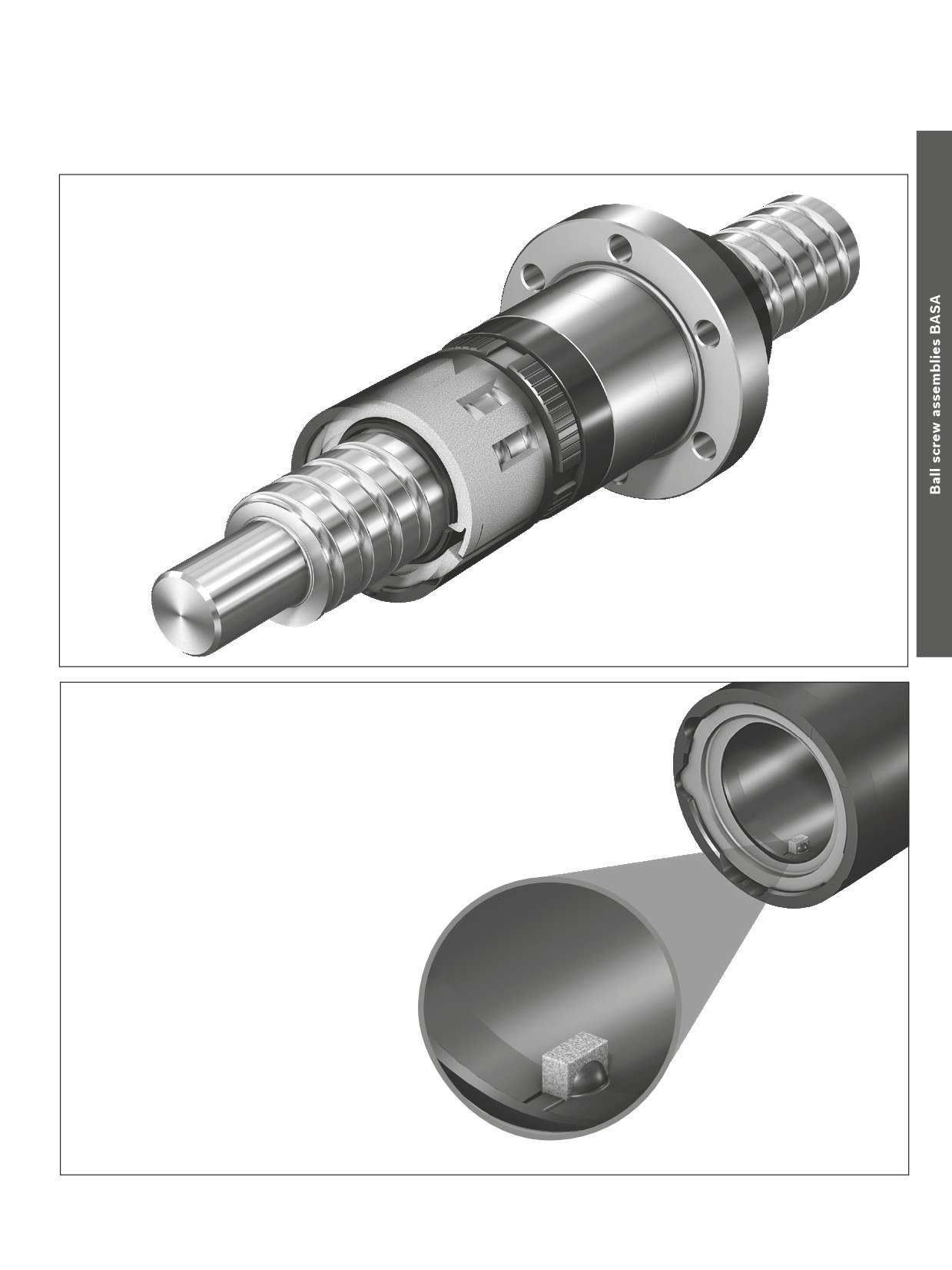
Structural design of front lube units
1
1 Seal
2 Housing and cover
2
--
Material: special plastic
3
3 Open-pored foam
4 Housing nut
4
5 Intermediate ring
5
6 Recirculation cap
6
7 Ball nut
8 Ball screw
7
Notes
When selecting the size for the stroke, consider the dimensions of the VSE.
8
When setting up a system, do not allow the VSE to collide with a stop or other
components.
127
Accessories
Contact zone of the open-pored foam
128
Screw Assemblies | Ball Screw Assemblies BASA
Accessories
Ball Nut with Front Lube Unit
Front lube unit
The front lube unit (VSE) has been designed for the long-term,
The front lube unit can be combined with the following nut types:
maintenance-free operation of the Ball Screw Assembly. It is
-–
FEM-E-S
-- FED-E-B
attached to the nut and delivers lube oil continuously to the rolling
-–
FEM-E-B
-- FDM-E-S
elements.
-–
SEM-E-S
-- FDM-E-B
For travel up to 300 million revolutions without relubrication.
--
SEM-E-C
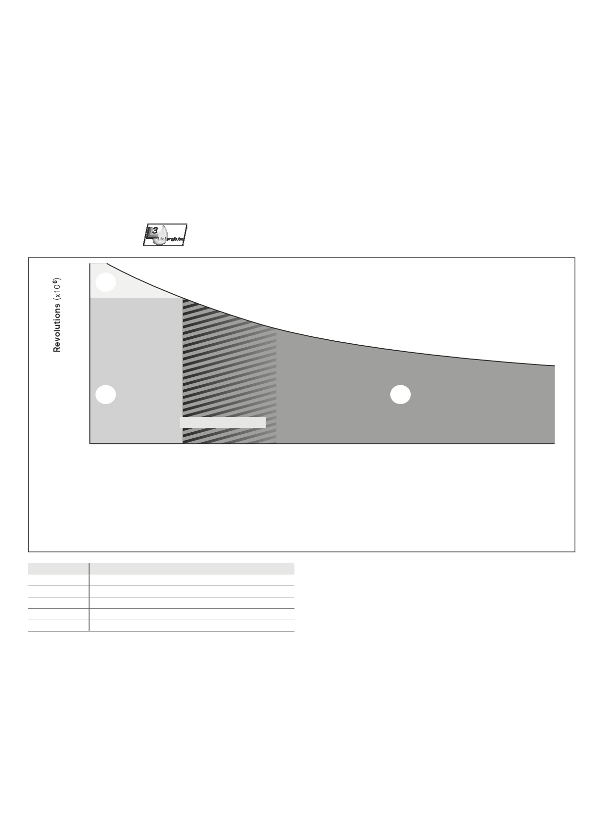
Lifelong lubrication
1
Lifelong lubrication
3
300
2
Maintenance-free up to 300 x 106 revolutions
3
Relubrication required
100
10
2
1
Normal operating load
1
10%
15%
20%
25 %
30 %
relative load (% C)
Results confirmed by our extensive tests:
1
For axial loads of 15-35% of the dynamic load rating C, the ball nut will
3
After 300 million revolutions, the ball nut should be relubricated as
be lubed for life.
usual. The front lube unit does not have to be removed from the nut.
2
For axial loads of < 15% of the dynamic load rating C, the Ball Screw
Assembly will require no maintenance for up to 300 million revolutions.
Lead (mm)
Travel s with Front Lube Units1) (km)
5
1,500
10
3,000
20
6,000
32
9,600
40
12,000
1) max. load up to 0.15C
129
Accessories
Technical data
Ball Screw Assembly with front lube unit
R151735020
R151735020
max. 51
max. 51
Front lube unit
max. L
max. L
Size of VSE
Part number
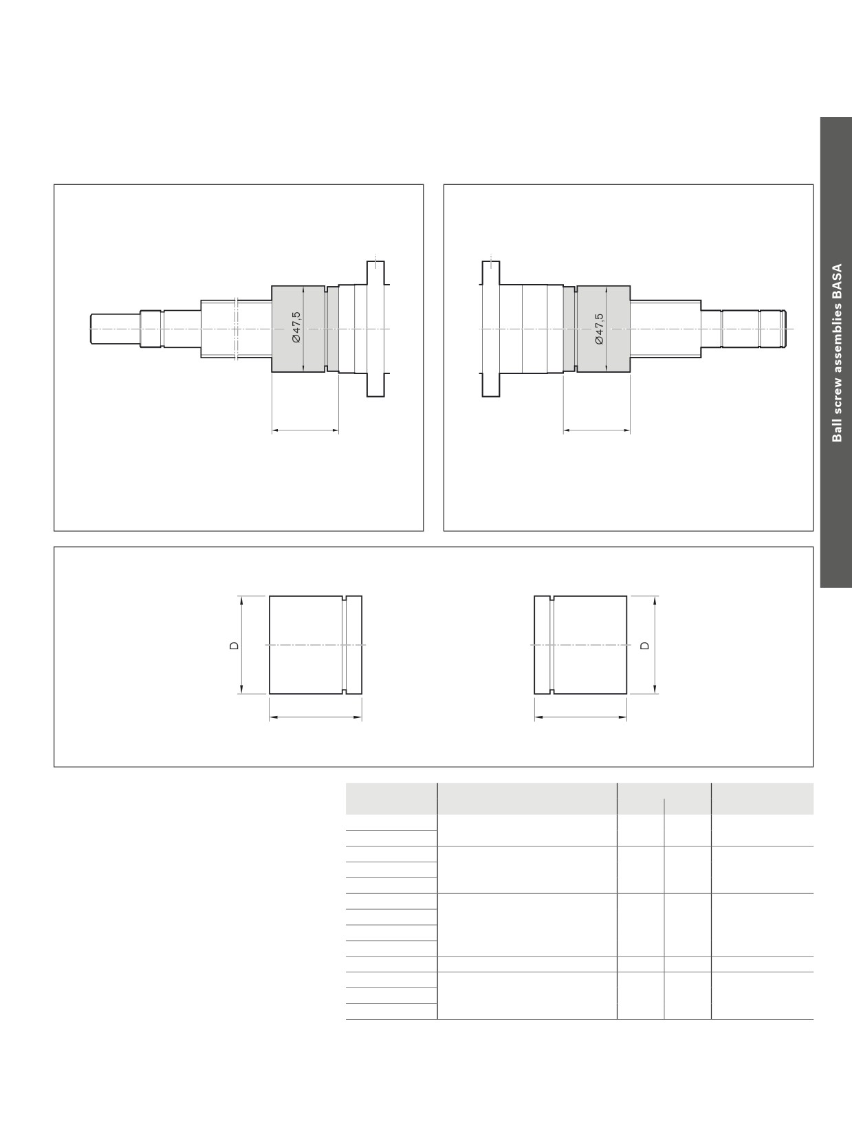
(mm)
Weight (kg)
Note: The front lube unit is delivered ready-
d0 x P
D
L
m
mounted to the Ball Screw Assembly.
20 x 5 R
R151715000
32.60
51.00
0,021
Only installation by the manufacturer is
20 x 20 R
permitted.
25 x 5 R
R151725010
37.50
51.00
0,027
25 x 10 R
25 x 25 R
32 x 5 R
R151735020
47.50
51.00
0,042
32 x 10 R
32 x 20 R
32 x 32 R
40 x 5 R
R151745030
55.50
53.00
0,055
40 x 10 R
R151745040
62.30
51.00
0,070
40 x 20 R
40 x 40 R
130
Screw Assemblies | Ball Screw Assemblies BASA
Accessories
Ball Nut with Front Lube Unit
BASA
32 x 10R x 3,969
FEM-E-S - 5
00
1
3
T7
R
81K203
31K200
1000
0
2
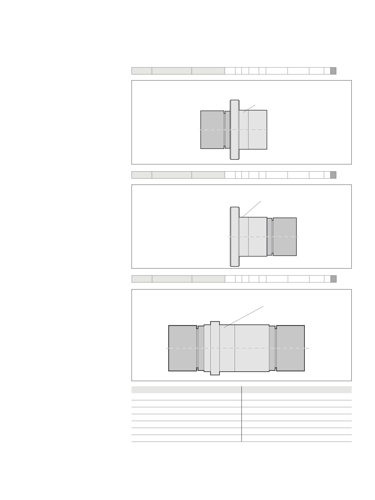
Ordering example for front lube unit with
illustration of mounting orientation
Front lube unit on left, nut with initial greasing
Nut Unit
Front lube unit
Centering diameter D1
(VSE)
BASA
32 x 10R x 3,969
FEM-E-S - 5
00
1
3
T7
R
81K203
31K200
1000
0
3
Front lube unit on right, nut with initial greasing
Nut unit
Centering diameter D1
Front lube unit
(VSE)
BASA
40 x 20R x 6
FED-E-B - 8
00
1
3
T7
R
81K250
31K300
1000
0
4
Front lube unit on two sides, nut with initial greasing
Nut unit
Centering diameter D1
Front lube unit
Front lube unit
(VSE)
(VSE)
Nut type
Mounting orientation
Mounting orientation of
FEM-E-S
2, 3
the front lube unit on nut types
FEM-E-B
2, 3
SEM-E-S
2, 3
SEM-E-C
2, 3
FED-E-B
4
FDM-E-S
2, 3
FDM-E-B
2, 3
131
Accessories
Measuring pads
Alignment of the Ball Screw Assembly
in the machine
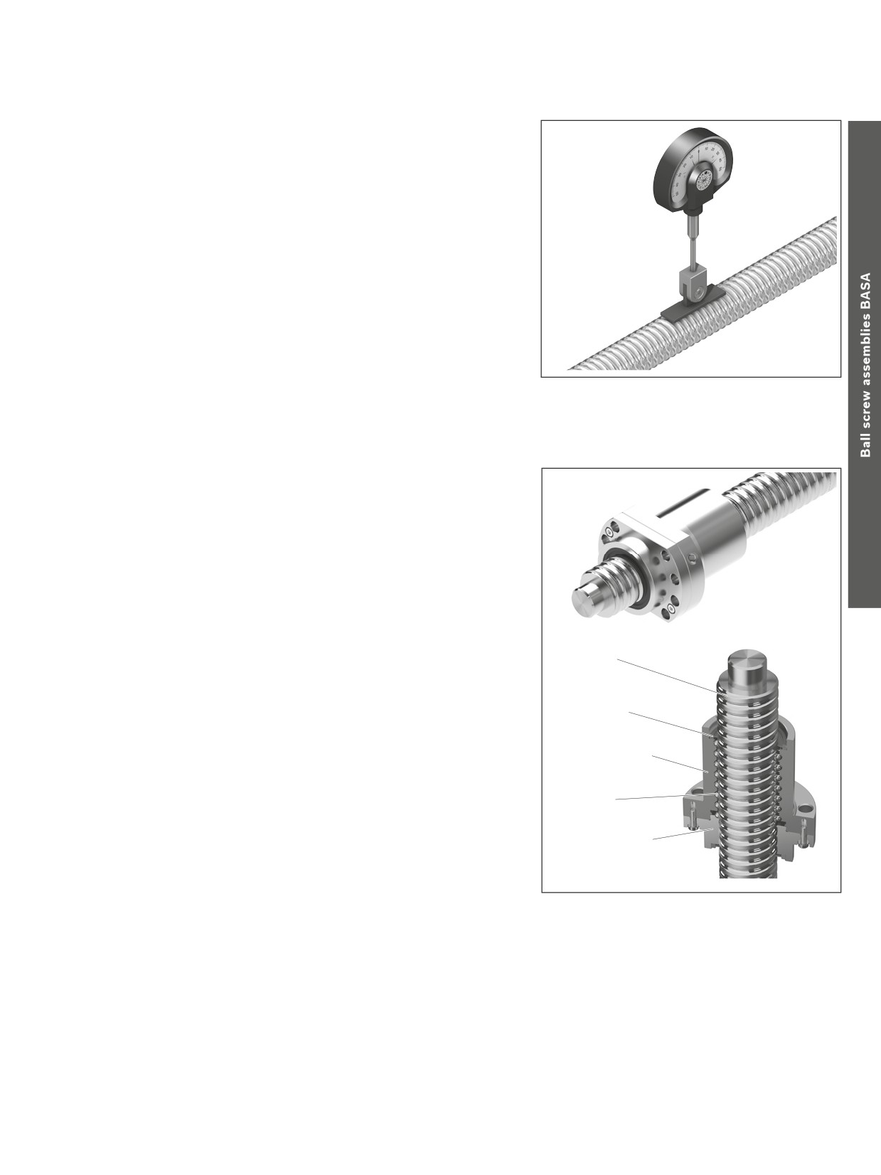
A gauge with a self-aligning contact pad is available from
Rexroth for easy alignment of the Ball Screw Assembly.
Two pads of different lengths are available which can be used
depending on the screw lead:
--
Part number R3305 131 19, length 33 mm for leads < 20
-–
Part number R3305 131 21, length 50 mm for leads > 20
Dial gauge not supplied as standard with the
Ball Screw Assembly
Arrestor nut
Assembly/set-up/ features
--
Installation on flange with hexagon socket screws for fixing the arrestor nut
--
Centering diameter prevents radial displacement
-–
Wiper seal is not mounted on the nut, but on the arrestor nut.
(This keeps dirt out of the space between the arrestor nut and the screw)
--
Length of the safety nut determines the safety factor
(Standard: 2-fold safety as against the static load capacity)
--
Multiple-thread arrestor nuts are used for multiple-thread screws
Recommended installation
The force or mass must always lie on the arrestor nut so that there is no
tensile loading of the fastening screws.
Screw
The fixed bearing of the screw should be located at the top.
Inspection may only be carried out by trained service engineers.
Seal
Design
Please consult our staff
Ball nut
Balls
Arrestor nut with
negative profile
Mode of operation
The ball nut with arrestor nut comprises the ball nut (for example, FEM-E-B) and an additional arrestor nut whose negative profile locks into
the screw raceway. The ball nut with arrestor nut basically works in the same way as a normal ball nut. If the ball nut fails to work
(for example, owing to a loss of balls), the arrestor nut thread comes into contact with the screw. This prevents an uncontrolled dropping of
the nut.
Use
In critical applications in non-horizontal operation (for example, in order to prevent damage to property). The arrestor nut is fitted to the nut
from below in the direction of force.
Arrestor nuts are not safety components within the meaning of the European Machinery Directive 2006/42/EC. Responsibility for the
safety of the structural design / specific application therefore still lies with you and the manufacturer. Particular attention must be paid to
ensuring that there are no hazards to people. Therefore, in particular in the case of vertically loaded axes, the structure must incorporate an
additional safety catch/holding device which prevents a drive component failure! The falling of the nut must be prevented in all cases.
132
Screw Assemblies | Ball Screw Assemblies BASA
Technical data
Technical notes
ISO 3408-1 defines a Ball Screw
Assembly as follows:
120
A ball screw drive (BASA) is a unit consist-
ing of a ball screw shaft, ball nut, and balls
Ball Screw Assembly
that is able to convert rotary motion into
100
linear motion, and vice versa.
Advantages over the Acme screw drive
80
Planetary Screw Assembly
--
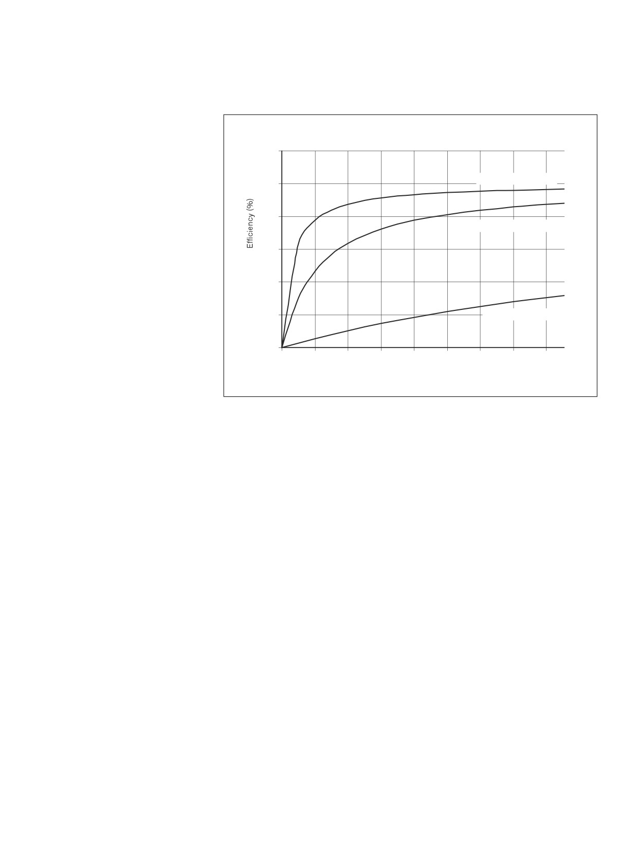
The maximum mechanical efficiency of
an Acme screw drive is 50%, whereas a
60
Planetary Screw Assembly can achieve
90%, and a Ball Screw Assembly 98%.
--
Higher life expectancy due to negligible
40
wear during operation
--
Less drive power required
-–
No stick-slip effect
20
Acme screw
--
More precise positioning
-–
Higher travel speed
-–
Less heat-up
0
0
1
2
3
4
5
6
7
8
Lead angle (°)
Due to the high level of effectivity (low
friction level between the screw and the
nut), ball screw drives are not self-locking.
cc
Safety information
If installing in a non-horizontal position,
Selection criteria for ball screw drives
customers should check whether separate
protection against falling loads is necessary,
The factors below are significant when rating a ball screw drive:
e.g. an arrestor nut. With particularly critical
--
Degree of accuracy required
applications in vertical operation, we recom-
(lead deviation)
mend installing arrestor nuts.
--
Load
Please consult us.
--
Service life
-–
critical speed
-–
buckling load
-–
rigidity/permissible clearance or desired preload
-–
characteristic speed (max. permissible linear speed)
The following points should be taken into consideration when selecting a PLSA that is to be
both cost-efficient and optimally designed:
--
The lead is a crucial factor in the load-bearing capacity (conditional on the maximum
possible ball diameter) and the drive torque.
--
The calculation of the service life should be based on average loads and average
speeds, not on maximum values.
--
In order for us to provide you with a customized solution, installation drawings or
sketches of the nut environment should be enclosed.
cc
Note
Radial and eccentric forces relative to the screw must be avoided, as they can negatively
affect the ball screw drive’s performance and shorten its service life.
Where special conditions of use are involved, please consult us.
133
Technical data
Load ratings and service life
Load rating:
Sealing
The calculations for the load capacities and
Short stroke applications will increase the
Ball screw drives need protection from
service lives are based on ISO 3408-5. The
number of times a rolling load passes over
contamination. Flat protective covers,
dynamic load capacities in the tables are
each point within the load zone.
bellows-type dust boots, or the AGK drive
above the ISO 3408-5 values. These values
This reduces the load rating.
unit are particularly suitable for this. Since
have been confirmed in tests.
there are many applications in which these
Critical speed and buckling load
methods do not provide sufficient protec-
Static load rating C0
The critical speed and buckling load can be
tion, we have developed a gapless lip-type
The static load rating is an axial, concentri-
checked using the corresponding charts.
seal which ensures an optimal sealing
cally acting force that induces a permanent
For precise calculations
effect and maintains high efficiency due to
deformation of 0.0001 x the ball diameter
see formula 12
15 , in the section “Design
the low friction level. This means that the
between the ball and the ball track.
Calculations3.”
standard versions of our ball screw drives
are supplied with seals. At the customer’s
Dynamic load rating C
Characteristic speed d0 · n
request, the seals can be omitted entirely
The dynamic load rating is an axial, concen-
Due to their structural design, Rexroth Ball
or special seals are used. For applications
trically acting force of constant magnitude
Screw Assemblies can be operated at very
where it appears that it is not possible to
and direction under which 90% of a suffi-
high speeds. Characteristic speeds of up
avoid severe contamination of the screw,
ciently large number of identical BASAs can
to 150,000 are possible depending on the
we have developed a reinforced variant of
achieve a nominal service life of one million
nut type.
the standard seal. The sealing effect has
revolutions.
d0 · n
≤
150,000
been enhanced even further by increasing
d0
= nominal diameter
(mm)
the preload. You should note the consider-
Correction factor for tolerance grades
n
= speed
(rpm)
ably higher frictional torque (see the techni-
The static load rating C0 and the dynamic
The theoretically possible maximum linear
cal data) compared to standard seals which
load rating C must be multiplied by the
speed vmax (m/min) is specified on the page
leads to greater heat generation. You can
correction factor fac as appropriate for the
featuring the relevant nut. Actually attain-
easily recognize the reinforced seal by its
specific tolerance grade of the screw.
able speeds are heavily dependent among
dark-green color.
other factors on preload and duty cycle.
Tolerance grade T
3
5
7
9
They are generally restricted by the critical
Permissible operating temperatures
fac
1
1
0,9
0,8
speed. (See “Design Calculations”).
Ball screw drives permit operation at
continuous temperatures of up to 80 °C
Service life
Material, hardness
with temporary peaks of 100 °C (measure-
The nominal service life is expressed by the
BASAs are made of high-quality, heat-
ments taken on the outer shell of the nut in
number of revolutions (or number of operat-
treatable steel, carbon chrome alloy steels
each case).
ing hours at constant speed) that will be
or case-hardened steels. The screw and
attained or exceeded by 90% of a repre-
nut raceways have a minimum Rockwell
sentative sample of identical BASAs before
hardness of HRC 58.
Permissible operating temperatures:
the first signs of material fatigue become
Ball screw drives made from stainless steel
-10 °C ≤ Toperation ≤ 80 °C
evident. The nominal life is designated as
(DIN EN 10088) are available on request.
L or Lh h, depending on whether it is speci-
Normally, the screw ends are not hardened.
Permissible storage temperature
fied in revolutions or hours.
-15 °C ≤ Tbearing ≤ 80 °C
Short stroke
Bearing
Short stroke applications = stroke ≤ nut
When calculating the life expectancy of the
length
overall system, the end bearings must be
Lubrication:
considered separately.
During a short stroke, the planets do not
make a real turn. It is therefore impossible
for an adequate lubricating film to form. This
may result in premature wear.
To avoid this, it is sufficient to perform
longer strokes at regular intervals with
simultaneous relubrication as “lubricating
strokes”.
Please consult our regional centers re-
garding short stroke applications.
You can find your local contact person
134
Screw Assemblies | Ball Screw Assemblies BASA
Technical data
Acceptance Conditions and Tolerance Grades
Permissible travel deviation
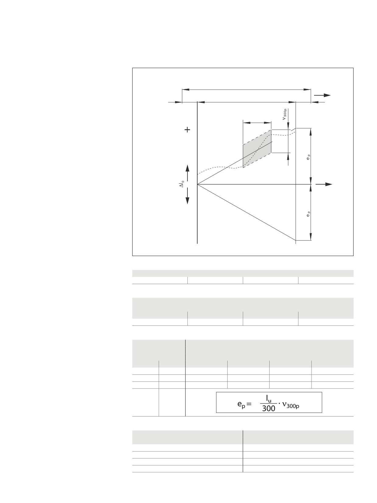
T
Ball Screw Assembly with precision screw
According to ISO 3408-3
l1
l0
Symbol definitions:
le
le
(excerpt)
lu
l0
= nominal travel
l1
= thread length
300
∆l0
= travel deviation
lu
= Useful travel
le
= excess travel (the closer tolerances for
travel and hardness do not apply here)
c
= travel compensation
(target travel deviation)
(standard: c = 0)
ep
= tolerance mean target travel deviation
ν300p= permissible travel deviation within
300 mm travel
a
= actual
p
= permissible
c = 0
Tolerance grade
Tolerance grades of
3
5
7
9
precision screws
ν300p (µm)
Permissible travel deviation
Tolerance grade
within 300 mm travel
3
5
7
9
12
23
52
130
Useful
Tolerance for target travel
Permissible target
travel lu
ep (µm)
travel deviation
Tolerance grade
>
≤
3
5
7
9
0
100
8
18
44
110
100
200
10
20
48
120
200
315
12
23
52
130
315
d0
le
Non-usable length le
(mm)
(mm)
(Excess travel)
6, 8
15
Modified compared to ISO 3408-3
12, 16
20
20, 25, 32, 40
40
50, 63, 80
50