Rexroth: Screw Assemblies. Catalog (R999001185/2020-03) - page 7
90
Screw Assemblies | Ball Screw Assemblies BASA
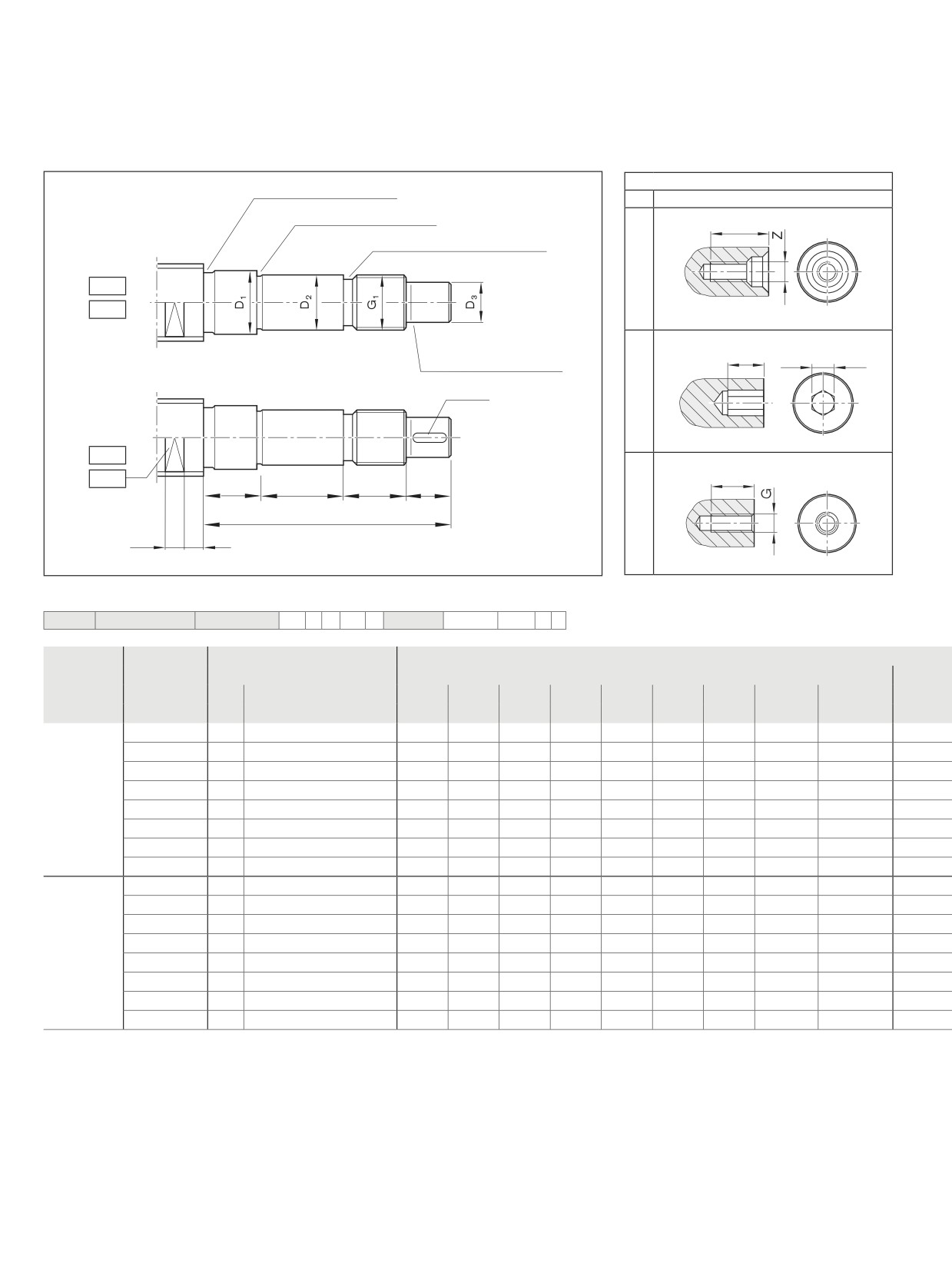
Screw Ends
Form N1, N1A, N2, N2A
Option (machining of end face)
Undercut Form E DIN 509
K
None
Undercut Form E DIN 509
Z
tZ
Thread undercut DIN 76 short
N1
N1A
S
tS
S
Undercut Form E DIN 509
b x l x t
N2
G
SW
N2A
tG
L1
L2
LG1
L3
Ljf
bSW
lSW
Ordering data:
BASA
25x5R x 3
SEM-E-S - 4
00
1
2
T7
R
A1K170
41Z170
1250
0
1
Form
Version1)
Size
(mm)
d0
P
Ljf
D1
L1
D2
L2
D3
L3
G1
LG1
h11
h6
h7
N1/N1A
170
25
5/10/25
85
21.0
10
17
23
15
30
M17x1
22
200
32
5/10/20/32
98
27.5
10
20
26
18
40
M20x1
22
250
40
10/12/16/20/25/30/40
140
33.5
10
25
54
22
50
M25x1.5
26
300
40
5
111
36.0
10
30
25
25
50
M30x1.5
26
301
50
10/12/16/20/25/30/40
103
43.0
10
30
25
25
50
M30x1.5
18
350
50
5
120
46.0
10
35
32
30
50
M35x1.5
28
400
63
10/20/40
142
56.0
10
40
44
36
60
M40x1.5
28
500
80
10/20
164
66.5
10
50
52
40
70
M50x1.5
32
N2/N2A
170
25
5/10/25
85
21.0
10
17
23
15
30
M17x1
22
200
32
5/10/20/32
98
27.5
10
20
26
18
40
M20x1
22
250
40
10/12/16/20/25/30/40
140
33.5
10
25
54
22
50
M25x1.5
26
300
40
5
111
36.0
10
30
25
25
50
M30x1.5
26
301
50
10/12/16/20/25/30/40
103
43.0
10
30
25
25
50
M30x1.5
18
350
50
5
120
46.0
10
35
32
30
50
M35x1.5
28
400
63
10/20/40
142
56.0
10
40
44
36
60
M40x1.5
28
500
80
10/20
164
66.5
10
50
52
40
70
M50x1.5
32
1) The allocation of screw ends to the bearing assemblies is clearly defined by the version.
Separate technical dimensioning of the
permissible drive torque is absolutely
necessary.
91
Screw ends
Version1)
Keyway
Centering hole
Hex socket
Thread
Wrench size
b
l
t
Z
tz
S
ts
G
tg
SW
bSW
lSW
P9
170
-
-
-
M5
12.5
4
4
M6
9
19
10
10.5
200
-
-
-
M6
16.0
5
5
M6
9
24
15
10.5
250
-
-
-
M8
19.0
6
6
M8
12
30
15
12.5
300
-
-
-
M10
22.0
8
8
M10
15
30
15
12.5
301
-
-
-
M10
22.0
8
8
M10
15
41
22
15.5
350
-
-
-
M10
22.0
10
10
M12
18
41
22
15.5
400
-
-
-
M12
28.0
12
12
M12
18
50
27
16.5
500
-
-
-
M16
36.0
12
12
M16
24
60
27
18.5
170
5
25
3.0
M5
12.5
4
4
M6
9
19
10
10.5
200
6
28
3.5
M6
16.0
5
5
M6
9
24
15
10.5
250
6
36
3.5
M8
19.0
6
6
M8
12
30
15
12.5
300
8
36
4.0
M10
22.0
8
8
M10
15
30
15
12.5
301
8
36
4.0
M10
22.0
8
8
M10
15
41
22
15.5
350
8
36
4.0
M10
22.0
10
10
M12
18
41
22
15.5
400
10
40
5.0
M12
28.0
12
12
M12
18
50
27
16.5
500
12
50
5.0
M16
36.0
12
12
M16
24
60
27
18.5
92
Screw Assemblies | Ball Screw Assemblies BASA
Accessories
Overview
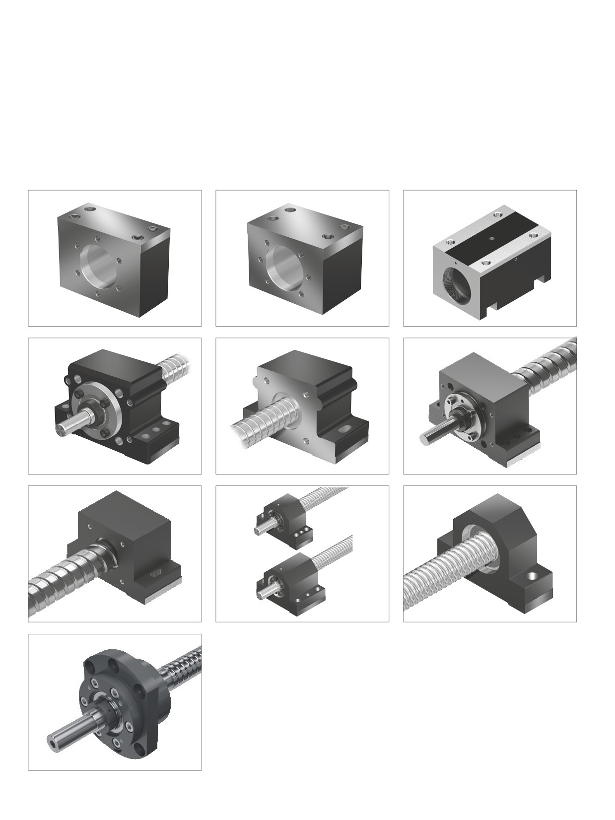
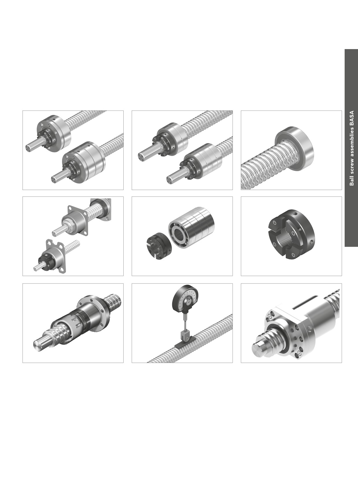
Rexroth offers an extensive range of accessories for ball screw assemblies.
These include Nut Housings, Pillow Block Units, bearings, Slotted Nuts, and Front Lube Units.
A reasonable ratio of the load capacities of the bearing and the ball screw drive should be taken into account when dimen-
sioning. Further information is provided in this section.
MGS
MGD
MGA
SEC-F
SEC-L
SES-F
SES-L
SEB-F
SEB-L
SEE-F-Z
93
Accessories
LAF
LAN
LAD
LAL
LAS
NMA
VSE
94
Screw Assemblies | Ball Screw Assemblies BASA
Accessories
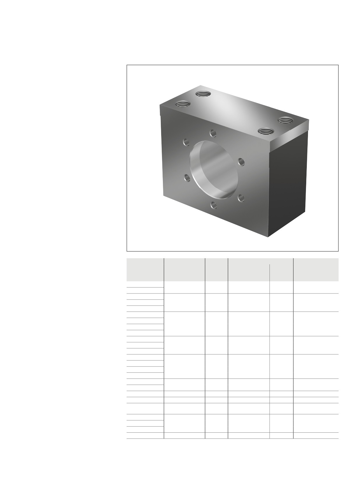
Nut housing MGS
Steel nut housings MGS are designed
for FEM-E-S, FDM-E-S, FEP-E-S and
SEM-E-S nuts
In addition to bolting, the housings should
be locked in place by positive means
(e.g. two pins with a diameter equal to that
of the screws S2).
We recommend using screws with a
strength class of 8.8.
Tightening torque
see “Installation in the machine” on page 147
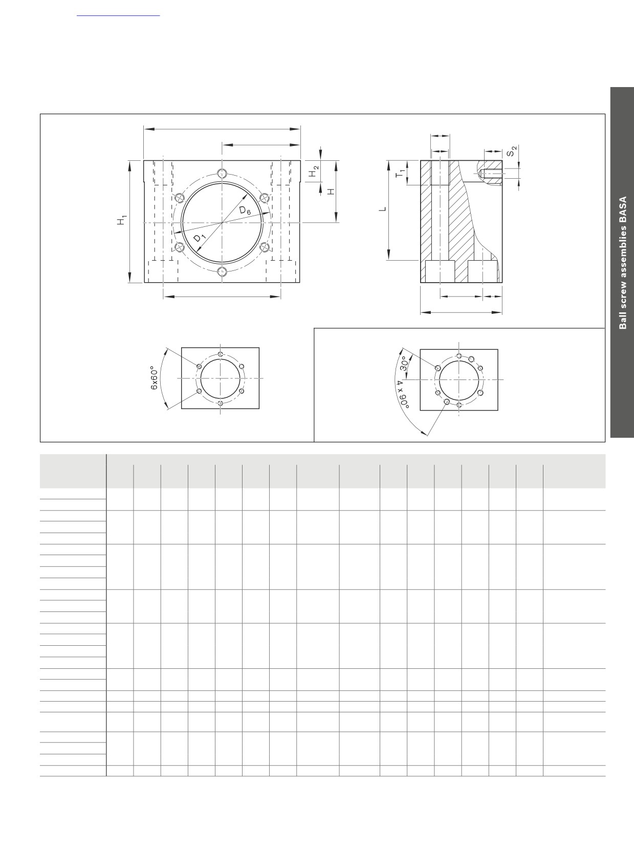
Reference edges are formed on both sides.
cc
If a Ball Screw Assembly with a
front lube unit is used, the front lube unit
may project beyond the housing. This
must be considered when calculating
the stroke.
Size
Mass
Hole pattern
Hex socket cap screw
(kg)
FEM-E-B /
SEM-E-S
ISO 4762
FEM-E-S /
d0 x P x Dw
Part number
FEP-E-S
16x5R/L x 3
R1506 000 20
0.850
BB3
BB7
M8
16x10R x 3
16x16R x 3
R1506 100 20
1.050
BB4
BB7
M8
20x5R/L x 3
20x10R x 3
20x20R x 3.5
R1506 200 20
1.178
BB4
BB7
M8
20x40R x 3.5
25x5R/L x 3
25x10R x 3
25x25R x 3.5
R1506 300 20
1.746
BB4
BB7
M10
32x5R/L x 3.5
32x10R x 3.969
32x20R x 3.969
R1506 400 20
2.367
BB4
BB7
M12
32x32R x 3.969
32x64R x 3.969
40x5R/L x 3.5
40x10R/L x 6
R1506 400 21
3.587
BB4
BB7
M14
40x20R x 6
40x40R x 6
R1506 500 21
6.187
BB4
BB7
M16
50x5R x 3.5
R1506 500 20
4.000
BB4
BB7
M14
50x10R x 6
R1506 500 21
6.187
BB4
BB7
M16
50x16R x 6
50x20R x 6.5
R1506 600 20
7.173
BB4
BB7
M16
50x40R x 6.5
63x10R x 6
80x10R x 6.5
R1506 700 20
9.334
BB4
BB7
M16
95
Accessories
2 x B
S
1
B
T2
S
E1
E2
N
A
for size 16x5/16x10
BB4/BB7
BB3 / BB7
Size
(mm)
d0 x P x Dw
D1
D6
A
B
H
H1
H2
E1
E2
N
S
S1
T1
S2
T2
Clamping length
H7
±0.01
±0.01
L
16x5R/L x 3
28
40
40
35.0
28
55
10
52±0.1
20±0.1
10
8.4
M10
15
M6
10
44.0
16x10R x 3
16x16R x 3
33
45
40
37.5
32
62
10
56±0.1
20±0.1
10
8.4
M10
15
M6
10
51.0
20x5R/L x 3
20x10R x 3
20x20R x 3.5
38
50
40
42.5
34
65
10
63±0.1
20±0.1
10
8.4
M10
15
M6
10
54.0
20x40R x 3.5
25x5R/L x 3
25x10R x 3
25x25R x 3.5
48
60
50
47.5
38
75
10
72±0.1
26±0.1
12
10.5
M12
15
M6
10
61.0
32x5R/L x 3.5
32x10R x 3.969
32x20R x 3.969
56
68
60
52.5
42
82
12
82±0.1
30±0.1
15
13.0
M16
20
M6
12
64.0
32x32R x 3.969
32x64R x 3.969
40x5R/L x 6
40x10R/L x 6
63
78
65
60.0
50
98
12
93±0.1
35±0.1
15
15.0
M18
25
M8
14
79.5
40x20R x 6
40x40R x 6
72
90
80
70.0
58
113
12
108±0.15
46±0.15
17
17.0
M20
30
M10
18
92.0
50x5R x 3.5
68
82
65
65.0
52
101
12
100±0.15
35±0.15
15
15.0
M18
30
M8
14
82.5
50x10R x 6
72
90
80
70.0
58
113
12
108±0.15
46±0.15
17
17.0
M20
30
M10
18
92.0
50x16R x 6
50x20R x 6.5
85
105
80
75.0
65
128
15
121±0.15
46±0.15
17
17.0
M20
30
M10
18
107.0
50x40R x 6.5
63x10R x 6
80x10R x 6.5
105
125
80
85.0
78
153
15
140±0.20
46±0.15
17
17.0
M20
30
M12
20
132.0
96
Screw Assemblies | Ball Screw Assemblies BASA
Accessories
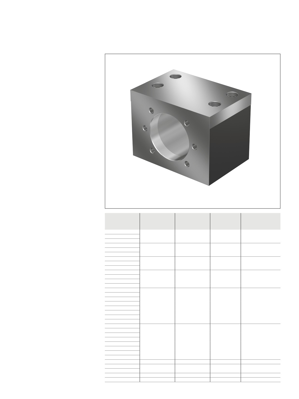
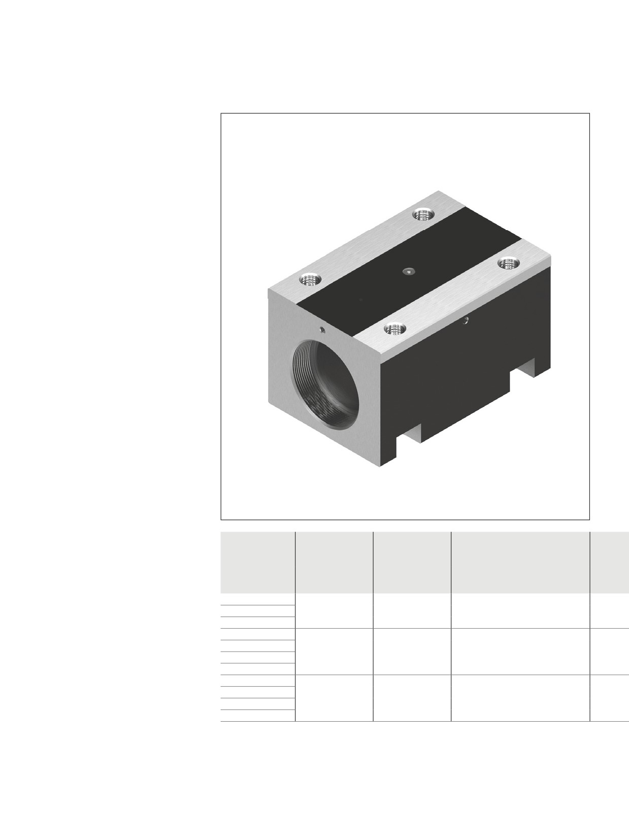
Nut housing MGD
Steel nut housings MGD are designed
for FEM-E-B, FDM-E-B, SEM-E-C and
FED-E-B nuts
In addition to bolting, the housings should
be locked in place by positive means
(for example, two pins with a diameter equal
to that of the screws).
We recommend using screws with a
strength class of 8.8.
Tightening torque
see “Installation in the machine” on page 147
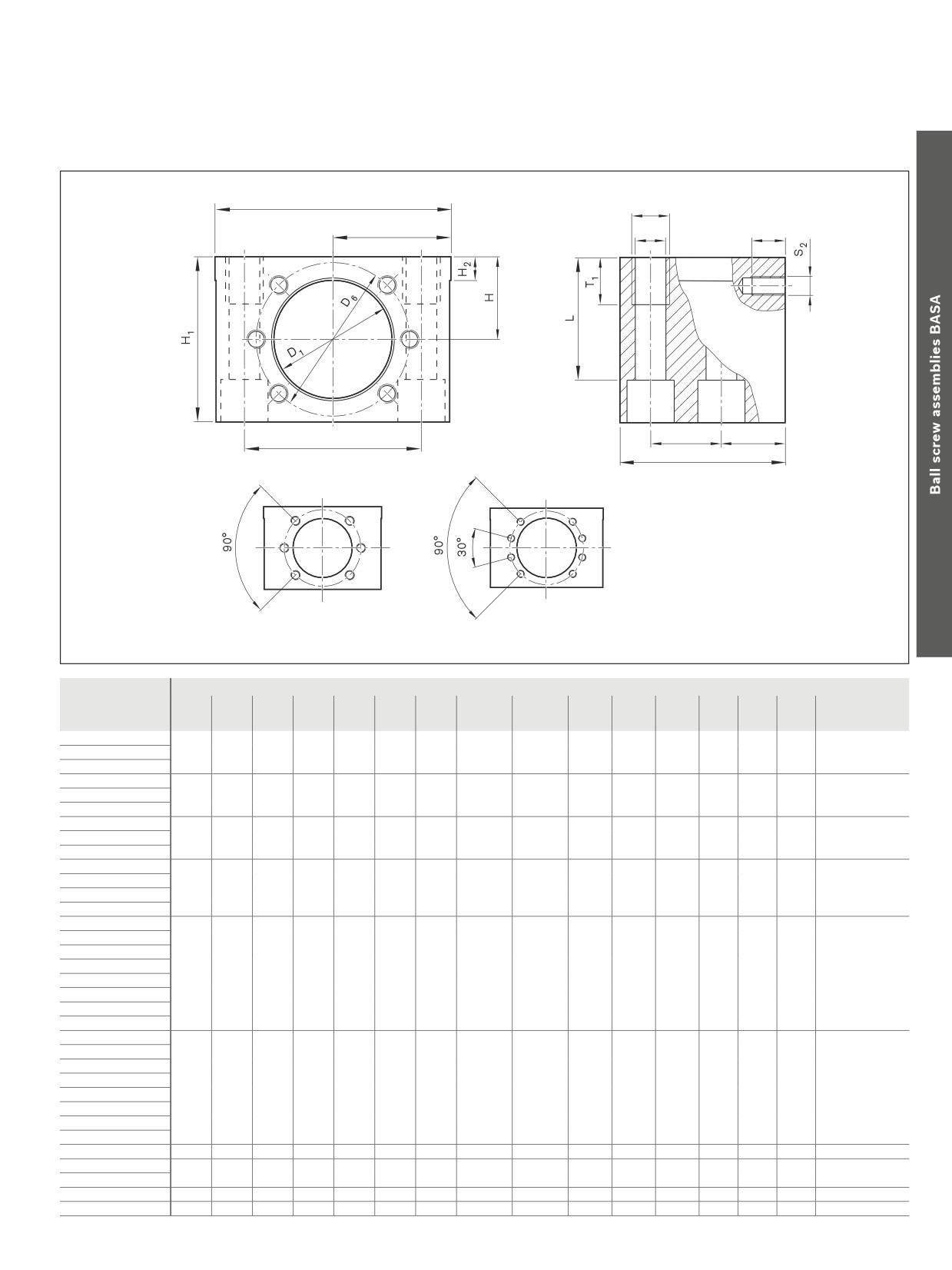
Reference edges are formed on both sides.
cc
If a Ball Screw Assembly with a
front lube unit is used, the front lube unit
may project beyond the housing. This
must be considered when calculating
the stroke.
Size
Part number
Mass
Hole pattern
Hex socket cap screw
ISO 4762
d0 x P x Dw
(kg)
16 x 5R/L x 3
R1506 000 50
0.91
BB2
M8
16 x 10R x 3
16 x 16R x 3
20 x 5R/L x 3
R1506 100 50
1.18
BB2
M8
20 x 10R x 3
20 x 20R x 3.5
25 x 5R/L x 3
R1506 200 50
1.33
BB2
M8
25 x 10R x 3
25 x 25R x 3.5
32 x 5R/L x 3.5
R1506 300 50
2.27
BB2
M12
32 x 10R x 3.969
32 x 20R x 3.969
32 x 32R x 3.969
40 x 5R/L x 3.5
R1506 400 50
3.61
BB1
M14
40 x 10R/L x 6
40 x 12R x 6
40 x 16R x 6
40 x 20R x 6
40 x 25R x 6
40 x 30R x 6
40 x 40R x 6
50 x 5R x 3.5
R1506 500 50
5.63
BB1
M16
50 x 10R x 6
50 x 12R x 6
50 x 16R x 6
50 x 20R x 6.5
50 x 25R x 6.5
50 x 30R x 6.5
50 x 40R x 6.5
63 x 10R x 6
R1506 600 50
6.72
BB1
M16
63 x 20R x 6.5
R1506 600 51
7.67
BB1
M16
63 x 40R x 6.5
80 x 10R x 6.5
R1506 700 50
8.60
BB1
M16
80 x 20R x 12.7
R1506 700 51
10.53
BB1
M16
97
Accessories
2 x B
S1
B
S
T2
E2
N
E1
A
BB2
BB1
Size
(mm)
D1
D6
A
B
H
H1
H2
E1
E2
N
S
S1
T1
S2
T2
Clamping length
d0 x P x Dw
H7
±0,01
±0,01
L
16 x 5R/L x 3
28
38
50
35
24
48
10
50 ±0.1
20 ±0.1
20
8.4
M10
15
M5
10
37.0
16 x 10R x 3
16 x 16R x 3
20 x 5R/L x 3
36
47
55
37.5
28
56
10
55 ±0.1
23 ±0.1
22
8.4
M10
15
M6
11
45.0
20 x 10R x 3
20 x 20R x 3.5
25 x 5R x 3
40
51
55
40
30
60
10
60 ±0.1
23 ±0.1
22
8.4
M10
15
M6
11
49.0
25 x 10R x 3
25 x 25R x 3.5
32 x 5R/L x 3.5
50
65
70
50
35
70
10
75 ±0.1
30 ±0.1
27
13.0
M16
20
M8
14
52.0
32 x 10R x 3.969
32 x 20R x 3.969
32 x 32R x 3.969
40 x 5R/L x 3.5
63
78
80
60
42
84
12
90 ±0.1
35 ±0.1
31
15.0
M18
25
M8
17
65.5
40 x 10R/L x 6
40 x 12R x 6
40 x 16R x 6
40 x 20R x 6
40 x 25R x 6
40 x 30R x 6
40 x 40R x 6
50 x 5R x 3.5
75
93
95
70
48
96
12
110 ±0.15
45 ±0.15
34
17.0
M20
30
M10
17
75.0
50 x 10R x 6
50 x 12R x 6
50 x 16R x 6
50 x 20R x 6.5
50 x 25R x 6.5
50 x 30R x 6.5
50 x 40R x 6.5
63 x 10R x 6
90
108
100
75
55
110
15
120 ±0.2
46 ±0.15
37
17.0
M20
30
M10
20
89.0
63 x 20R x 6.5
95
115
100
80
58
116
15
130 ±0.2
46 ±0.15
37
17.0
M20
30
M12
20
95.0
63 x 40R x 6.5
80 x 10R x 6.5
105
125
100
85
63
126
15
140 ±0.2
46 ±0.15
37
17.0
M20
30
M12
20
105.0
80 x 20R x 12.7
125
145
100
95
73
146
15
160 ±0.2
46 ±0.15
37
17.0
M20
30
M12
22
125.0
98
Screw Assemblies | Ball Screw Assemblies BASA
Accessories
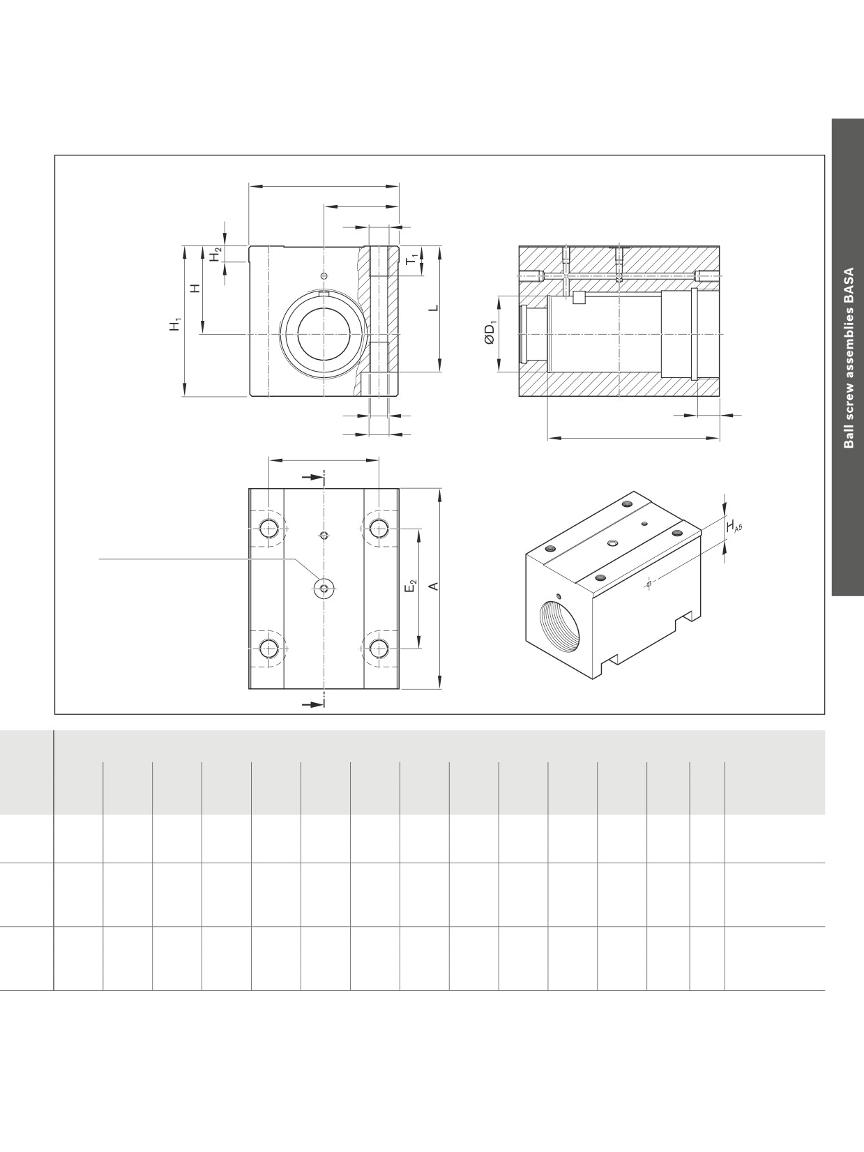
Nut housing MGA
Aluminum nut housings MGA are
designed for ZEM-E-S, ZEM-E-K
and ZEM-E-A nuts
We recommend using screws with
a strength class of 8.8.
Tightening torque
see “Installation in the machine” on page 147
Reference edges are formed on both sides.
Scope of delivery: Includes set screws,
spacer ring, ring nut, washer key
Size
Mass
Hex socket cap screw for
screwing from below ISO 4762
d0 x P x DW
Part number
(kg)
20 x 5R x 3
R1506 100 70
1.10
M8
20 x 10R x 3
20 x 20R x 3.5
32 x 5R x 3.5
R1506 300 70
2.31
M10
32 x 10R x 3.969
32 x 20R x 3.969
32 x 32R x 3.969
40 x 5R x 3.5
R1506 400 70
4.32
M14
40 x 10R x 6
40 x 20R x 6
40 x 40R x 6
99
Accessories
2 x B
B
S1
A - A
S
T2
S
1
T3
E1
A
Countersink for O-ring 7 x 1.5
A
(mm)
Clamping length
A
B
ØD1
E1
E2
H
H1
H2
HA5
S
S1
T1
T2
T3
L
±0.01
H6
±0.01
100
37.5
38
55
60
44
75
8
15
8.6
M10
15
11
86
63
150
50.0
50
75
100
49
80
9
16
10.5
M12
18
15
131
66
180
60.0
63
90
120
59
105
10
18
14.5
M16
24
20
155
86
100
Screw Assemblies | Ball Screw Assemblies BASA
Accessories
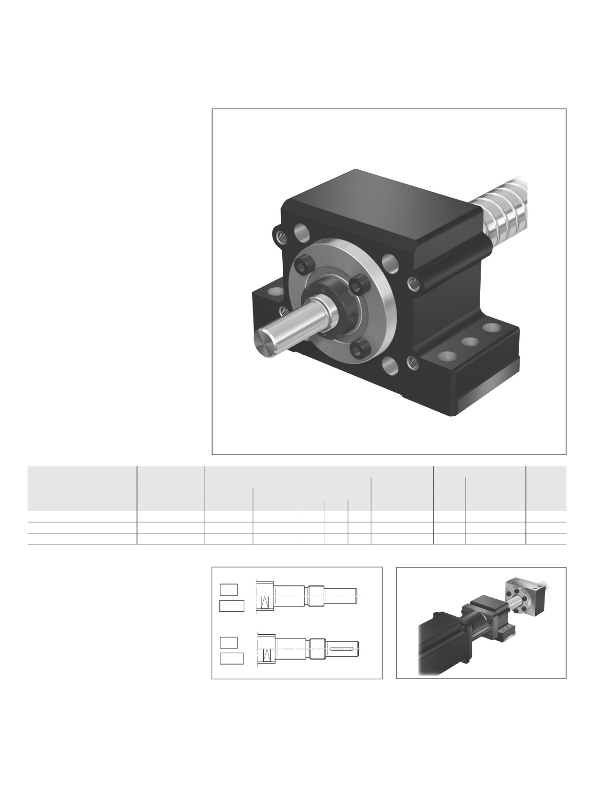
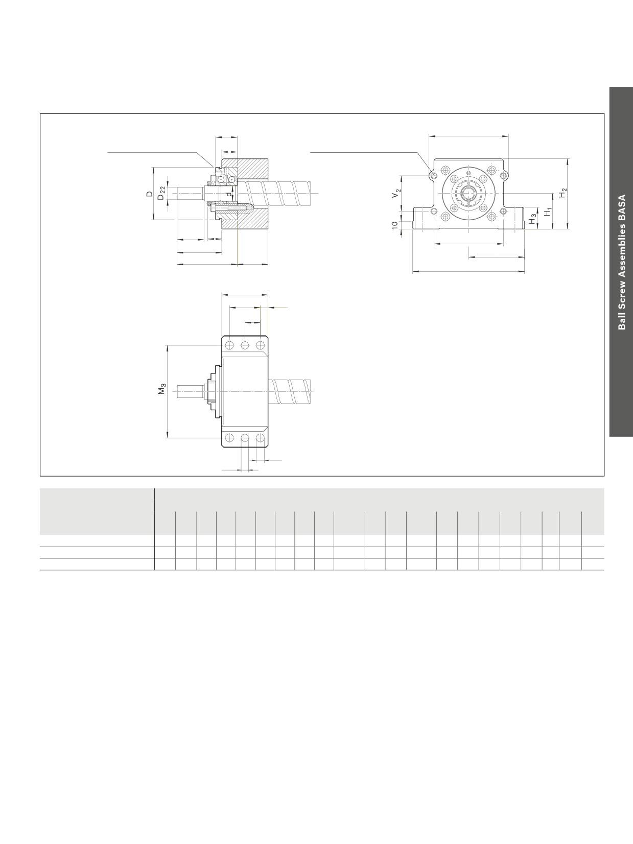
Pillow Block Unit SEC-F assembly, aluminum
Fixed bearing with angular-
contact thrust ball bearing
LGF-B-…
The pillow block unit consists of:
--
Precision pillow block housing made of
aluminum with reference edges on both
sides
--
Angular-contact thrust ball bearing LGF...
-–
Slotted nut NMZ
The slotted nut is delivered unmounted.
Separate technical dimensioning to
determine the limit values is absolutely
necessary for all attachments (e.g. pillow
block units, bearing assembly, etc.)
Size
Complete pillow
Angular-contact thrust ball bearing
Slotted nut
Weight
block
Load ratings (axial)
(mm)
Abbreviation
Abbreviation
complete
dyn. C
stat. C0
MA
d0 x P
Part number
(N)
(N)
d
D
B
(Nm)
(kg)
20x5/10/20/40
R1594 012 00
17,000
24,700
12
55
25
LGF-B-1255
8.0
NMZ 12x1
1.49
32x5/10/20/32/64
R1594 020 00
26,000
47,000
20
68
28
LGF-B-2068
18.0
NMZ 20x1
1.88
40x5/10/12/16/20/25/30/40
R1594 030 00
29,000
64,000
30
80
28
LGF-B-3080
32.0
NMZ 30x1.5
2.75
Screw end Form 81, 81A, 82, 82A
designed for motor mounting.
81
81A
82
82A
101
Accessories
M 2
Centering diameter D
B
Fastening thread S3 x T3
for motor flange
L
4
for motor flange
L 22
L
3
V
1
L
2
M1
L
20
L
1
2 x M
1
B1
40
B
2
20
S1
S 2
Size
(mm)
B1
B2
L1
L2
L3
L4
L20
L22
D22
M1
M2
M3
H1
H2
H3
S1
S2
S3
T3
V1
V2
d0 x P
±0.015
±0.015
20x5/10/20/40
60
10.0
42
42
15
18
60
25
10
72.5
80
120
41
81
28
10.5
9.7
M8
15
66
50
32x5/10/20/32/64
60
10.0
40
58
18
20
78
35
16
72.5
103
120
46
91
28
10.5
9.7
M8
15
90
46
40x5/10/12/16/20/25/30/40
65
12.5
45
73
20
20
93
50
25
90.0
116
150
56
111
33
13.0
11.7
M10
20
100
65
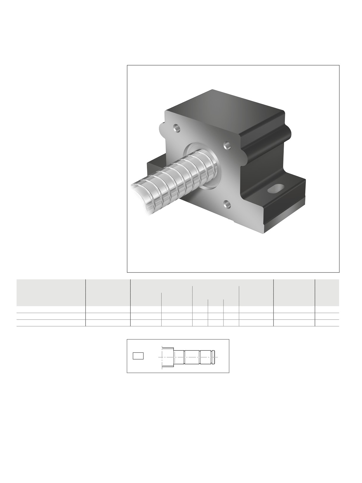
102
Screw Assemblies | Ball Screw Assemblies BASA
Accessories
Pillow Block Unit SEC-L assembly, aluminum
Floating bearing with DIN 625
deep-groove ball bearing
The pillow block unit consists of:
--
Precision pillow block housing made of
aluminum with reference edges on both
sides
--
Deep-groove ball bearing as per
DIN 625
--
Retaining ring DIN 471
-–
Cover
All parts are delivered unmounted.
Separate technical dimensioning to
determine the limit values is absolutely
necessary for all attachments (e.g. pillow
block units, bearing assembly, etc.)
Size
Complete pillow
Deep-groove ball bearing as per DIN 625
Retaining ring as
Weight
block
Load ratings (radial)
(mm)
Designation
per DIN 471
complete
dyn. C
stat. C0
DIN 625...
d0 x P
Part number
(N)
(N)
d
D
B
(kg)
20x5/10/20/40
R1594 615 00
7,800
3,250
15
35
11
6202.2RS
15x1
1.24
32x5/10/20/32/64
R1594 620 00
12,700
5,700
20
47
14
6204.2RS
20x1.2
1.66
40x5/10/12/16/20/25/30/40
R1594 630 00
19,300
9,800
30
62
16
6206.2RS
30x1.5
2.74
Suitable for screw ends: Form
31
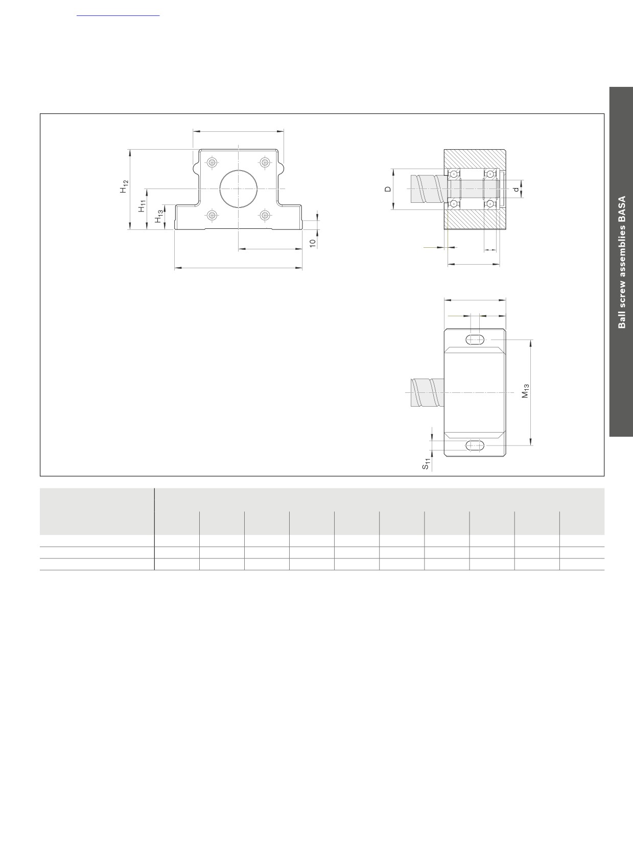
103
Accessories
M
12
M11
4
B
L31
2 x M11
B11
10
B12
Size
(mm)
B11
B12
L31
M11
M12
M13
H11
H12
H13
S11
d0 x P
±0.015
±0.015
20x5/10/20/40
60
25
47
72.5
80
120
41
81
28
10.5
32x5/10/20/32/64
70
30
60
72.5
103
120
46
91
28
10.5
40x5/10/12/16/20/25/30/40
80
35
68
90.0
116
150
56
111
33
13.0
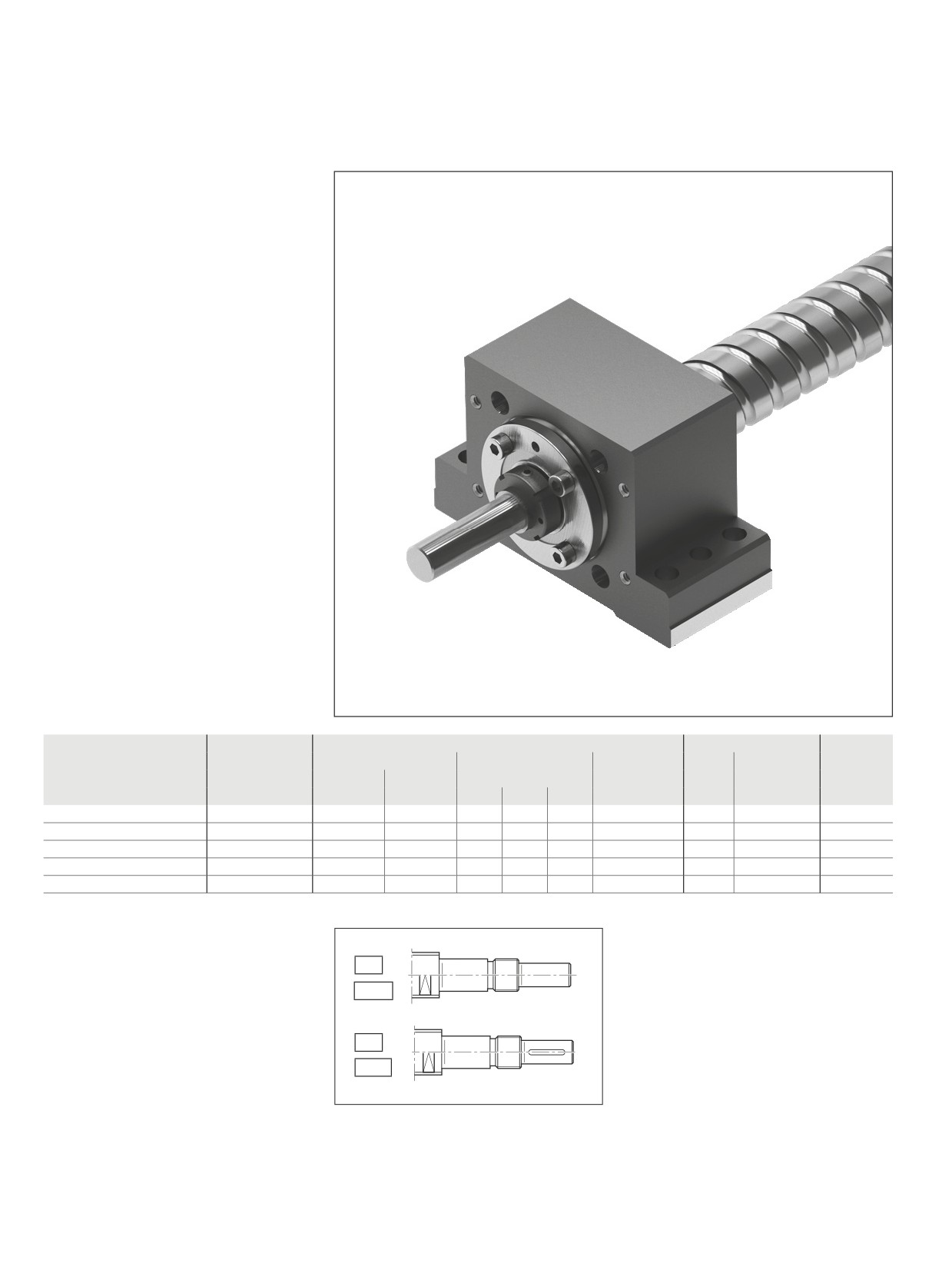
104
Screw Assemblies | Ball Screw Assemblies BASA
Accessories
Pillow Block Unit SES-F assembly, steel
Fixed bearing with angular-
contact thrust ball bearing
LGF-B-…, LGF-C-...
The pillow block unit consists of:
--
Precision pillow block housing made of
steel with reference edges on both sides
--
Angular-contact thrust ball bearing LGF...
-–
Slotted nut NMZ
The slotted nut is delivered unmounted.
Separate technical dimensioning to
determine the limit values is absolutely
necessary for all attachments (e.g. pillow
block units, bearing assembly, etc.)
Size
Complete pillow
Angular-contact thrust ball bearing
Slotted nut
Weight
block
Load ratings (axial)
(mm)
Abbreviation
Abbreviation
complete
dyn. C
stat. C0
MA
d0 x P
Part number
(N)
(N)
d
D
B
(Nm)
(kg)
20x5/10/20/40
R1595 012 20
17,000
24,700
12
55
25
LGF-B-1255
8
NMZ 12x1
3.37
25x5/10/25
R1595 017 20
18,800
31,000
17
62
25
LGF-B-1762
15
NMZ 17x1
3.38
32x5/10/20/32/64
R1595 020 20
26,000
47,000
20
68
28
LGF-B-2068
18
NMZ 20x1
4.31
40x5
R1595 030 20
29,000
64,000
30
80
28
LGF-B-3080
32
NMZ 30x1.5
6.31
40x10/12/16/20/25/30/40
R1595 330 20
47,500
127,000
30
80
56
LGF-C-3080
32
NMZ 30x1.5
7.53
Screw end Form 81, 81A, 82, 82A
designed for motor mounting.
81
81A
82
82A
Further information on the bearing pair can
be found on page 114.