Rexroth: Screw Assemblies. Catalog (R999001185/2018-10) - page 19
Planetary Screw Assemblies PLSA | Screw Assemblies
271
Calculation
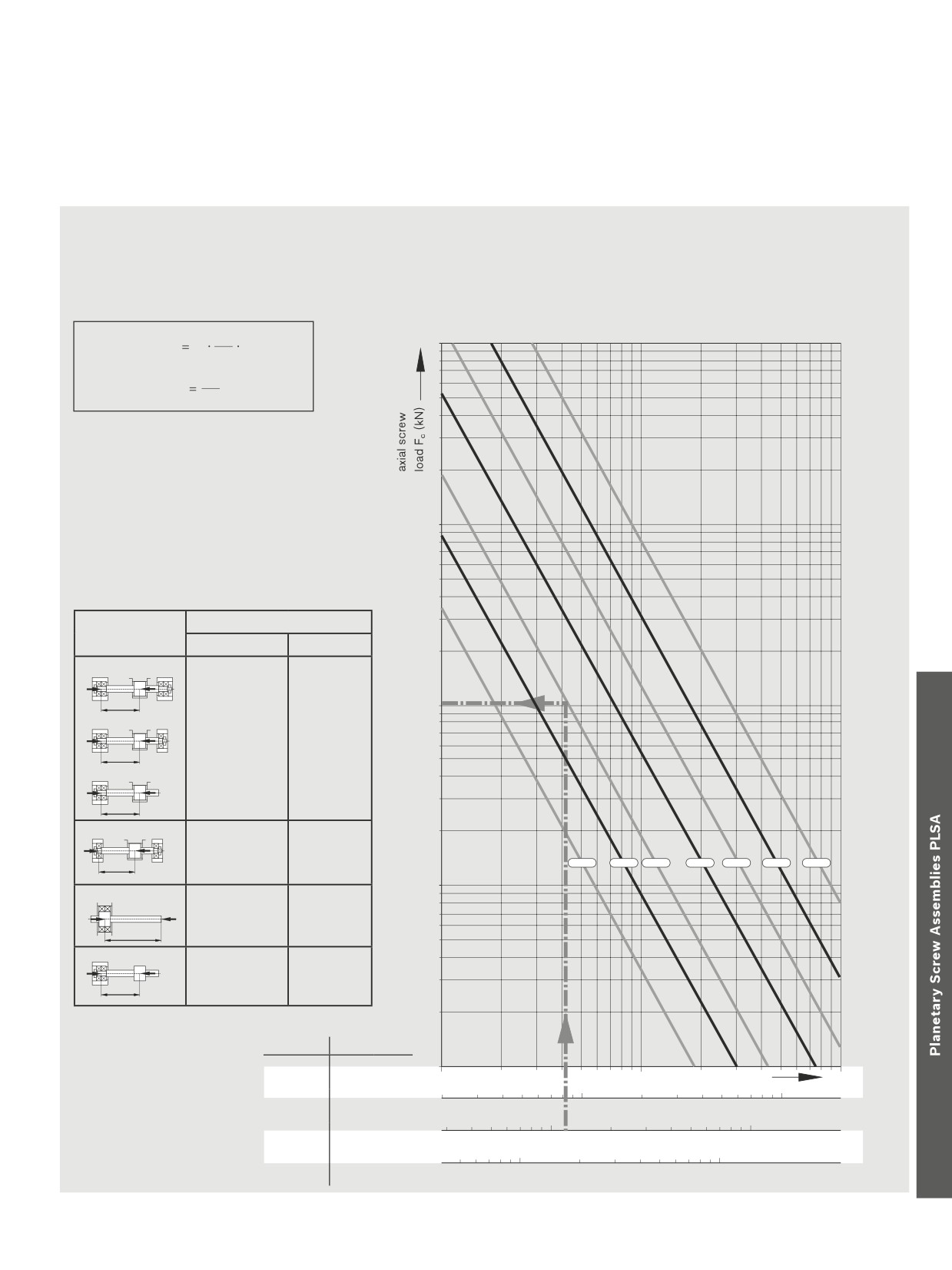
Permissible axial load on screw
The permissible axial load on the screw Fc
A safety factor of s ≥ 2 must be taken into
Fc (buckling load)
depends on the diameter of the screw, the type of
consideration when determining the permis-
end fixity, and the effective unsupported length lc.
sible axial load.
Example
Screw diameter
=
30 mm,
According to the graph, the theoretically permis-
This therefore lies above the maximum operat-
Length lc
=
1,200 mm
sible axial load is 115 kN.
ing load of F1 = 50 kN used in our calculation
End fixity IV (fixed bearing - floating bearing)
Applying the safety factor 2 yields a permissible
example.
axial load on the screw in operation of
For more information on buckling, see next page.
115 kN : 2 = 57.5 kN.
d24
4
10000
15
F
10
(N)
c fFc
lc2
16
Fcp
(N)
Fc2
Fc
= Theoretically permissible axial
load on screw
Fcp
= Permissible axial load on screw
during operation (N)
fFc
= Corrector value determined by
bearing
1000
d2
= Root diameter of screw, see
dimension tables (mm)
lc
= unsupported thread length
End fixity:
coefficient fFc
nut fixed
nut floating
A - A
F
F
lc
100
A - B
F
F
End fixity I
End fixity IV
lc
40.6
20.4
A - C
F
F
lc
B - B
F
F
End fixity II
End fixity V
lc
20
25
30
39
48
60
75
20.4
10.2
10
A - C
F
F
End fixity III
lc
2.6
A - C
F
F
End fixity VI
lc
2.6
End fixity:
fFc value
End fixity
A = fixed bearing
2.6
III / VI
100
1000
Length lc (mm)
10000
B = floating bearing
C = without bearing
1000
10000
10.2
V
1000
10000
20.4
II / IV
1000
10000
40.6
I
272
Screw Assemblies | Planetary Screw Assemblies PLSA
End Bearings
Notes on buckling
The effective buckling length lc of the screw is the maximum unsupported screw length in the direction of the force’s flow between the nut
unit and the fixed bearing (center-to-center distance) or between the nut unit and the screw end.
For buckling load calculations, the nut is taken into consideration as a bearing.
For “nut fixed,” the following conditions must be met:
--
zero-backlash nut,
-–
rigid attachment of the nut to the linear guide,
-–
the nut unit is not subjected to moment loads, i.e. a linear guide absorbs any arising moments,
-–
no distortive stresses due to external factors (for example, temperature).
If one or more of the conditions for “nut fixed” are not met, the appropriate coefficients for “nut floating” must be used instead.
Case III occurs in applications with driven nuts, for example, when the nut is stationary and the screw rotates. The nut can then be
regarded as a fixed bearing.
CaseVI arises only when the nut unit is not supported by any linear guide.
End Bearings
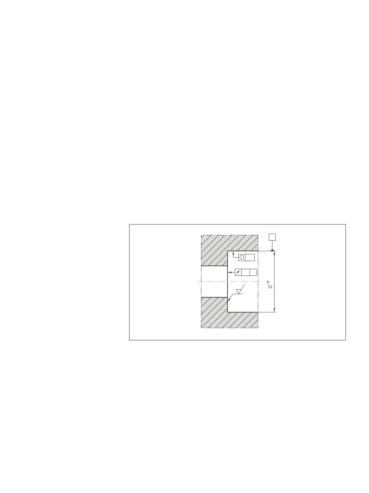
Design notes, installation
Housing
C
Bearing design
For customer-machined screw ends, please
consider the design notes given for screw
IT4
ends and housings.
For Rexroth screw end designs, see “End
IT5
C
Machining Details.”
Rexroth delivers complete drive systems,
1,6
including the end bearings. Calculations
are performed with the formulas used in the
antifriction bearing industry.
1,6
Planetary Screw Assemblies PLSA | Screw Assemblies
273
End Bearings
Mounting
Angular-contact thrust ball bearings and
deep-groove ball bearings
When mounting the angular-contact thrust
be subjected only to tension amounting to a
Outer raceway markings
ball bearings LGF and LGN, ensure that
maximum of 70% of their yielding point.
for paired bearings
the mounting forces are exerted only on
The screw-down (LGF) bearings have a
the bearing rings. Never apply mounting
groove on the cylindrical surface of the
forces via the anti-friction bearing elements
outer raceway for disassembly. The individ-
or the seal rings! The two sections of the
ual bearings of the bearing pair series
inner raceway may not be separated during
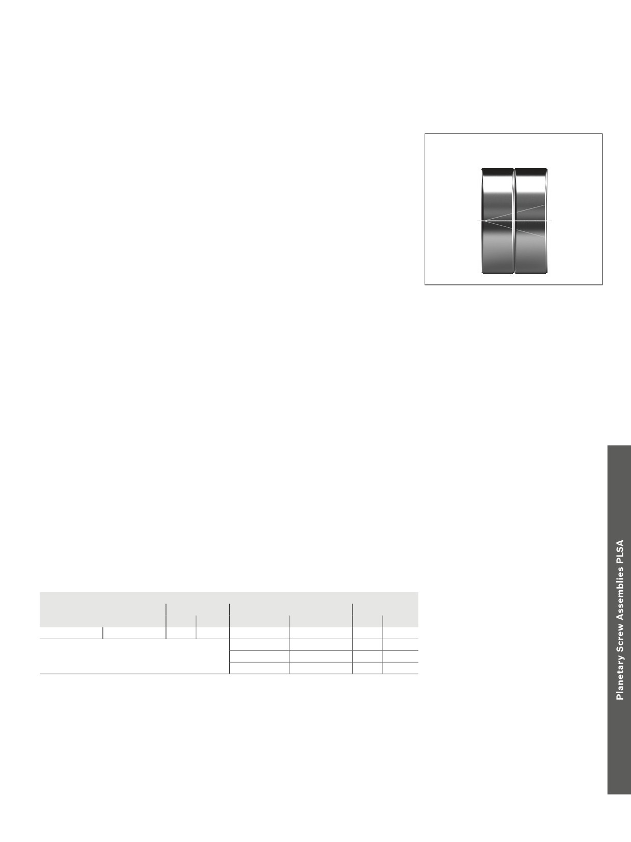
LGF-C... and LGN-C... are marked on the
assembly or disassembly for any reason!
cylindrical surfaces of the outer raceways
Tighten the mounting screws for screw-
(see Figure). The markings reveal the
down or flange-mounted bearings in cross-
bearing sequence. The sealing rings should
wise sequence. The mounting screws may
face outwards after proper mounting.
Slotted nut
The bearings are preloaded by tightening
The two set screws are then alternately
raceways of the bearings are dimensioned
the nuts.
tightened using a hexagon socket wrench.
in such a way as to achieve a defined
In order to prevent settling phenomena, we
The components are disassembled in the
bearing preload sufficient for most applica-
recommend first tightening the slotted nut
reverse order, i.e. the set screws have to be
tions when the slotted nut is tightened
by twice the value of the tightening torque
removed before the slotted nut.
(MA in accordance with Dimension Table).
MA and then easing the load. Only then
The slotted nuts can be used several times
should the slotted nut be retightened to the
when properly assembled and disassem-
specified tightening torque MA.
bled by competent personnel. The inner
Lubrication of the end bearings
Bearings for Panetary Screw Assemblies are lubricated with grease for a lifetime of reliable service. It should be noted, however, that grease
lubrication does not facilitate the dissipation of heat in the bearings. The bearing temperature should therefore not exceed 50 °C, particularly
in machine tool applications. At higher temperatures circulating oil lubrication must be set up. Angular-contact thrust ball bearings of series
LGF, LGN are lifetime-lubricated with KE2P-35 grease as per DIN 51825. For regreasing, the quantities stated in the table below can be
applied via the lube ports provided on the bearings. Where there are pairs of bearings, please note that each bearing must be individually
lubricated via the lube port. Each bearing must be lubricated with half the value shown in the table.The maximum interval can be assumed to
be 350 million revolutions, in which case the larger of the two quantities should be used. As a rule, the initial grease quantity will therefore
last for the entire service life of a Planetary Screw Assembly.
Relubrication quantities for angular-contact thrust ball bearings
Abbreviation
Quantity (cm3)
Abbreviation
Quantity (cm3)
1)
2)
1)
LGN-B-1545
LGF-B-1560
0.49
0.38
LGN-C-2052
LGF-C-2068
1.74
1.09
LGN-C-3062
LGF-C-3080
2.17
1.30
LGN-C-3572
LGF-C-3590
3.48
1.96
1) Shortened lubricating interval max. 10 M revolutions
2) Where there are pairs of bearings, lubricate each bearing via the lube port.
Lubricate each bearing with half the value shown in the table.
274
Screw Assemblies | Planetary Screw Assemblies PLSA
End Bearings
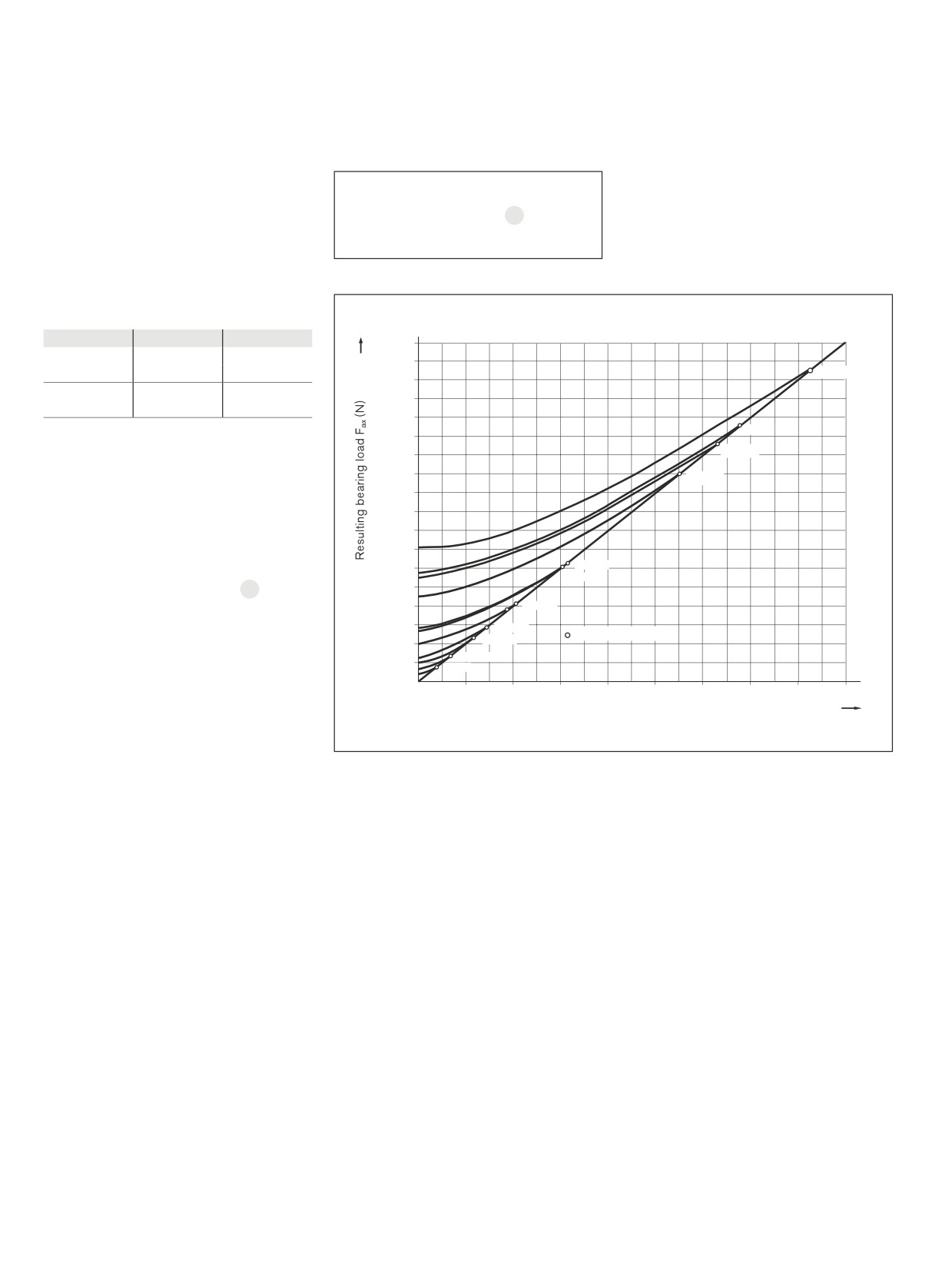
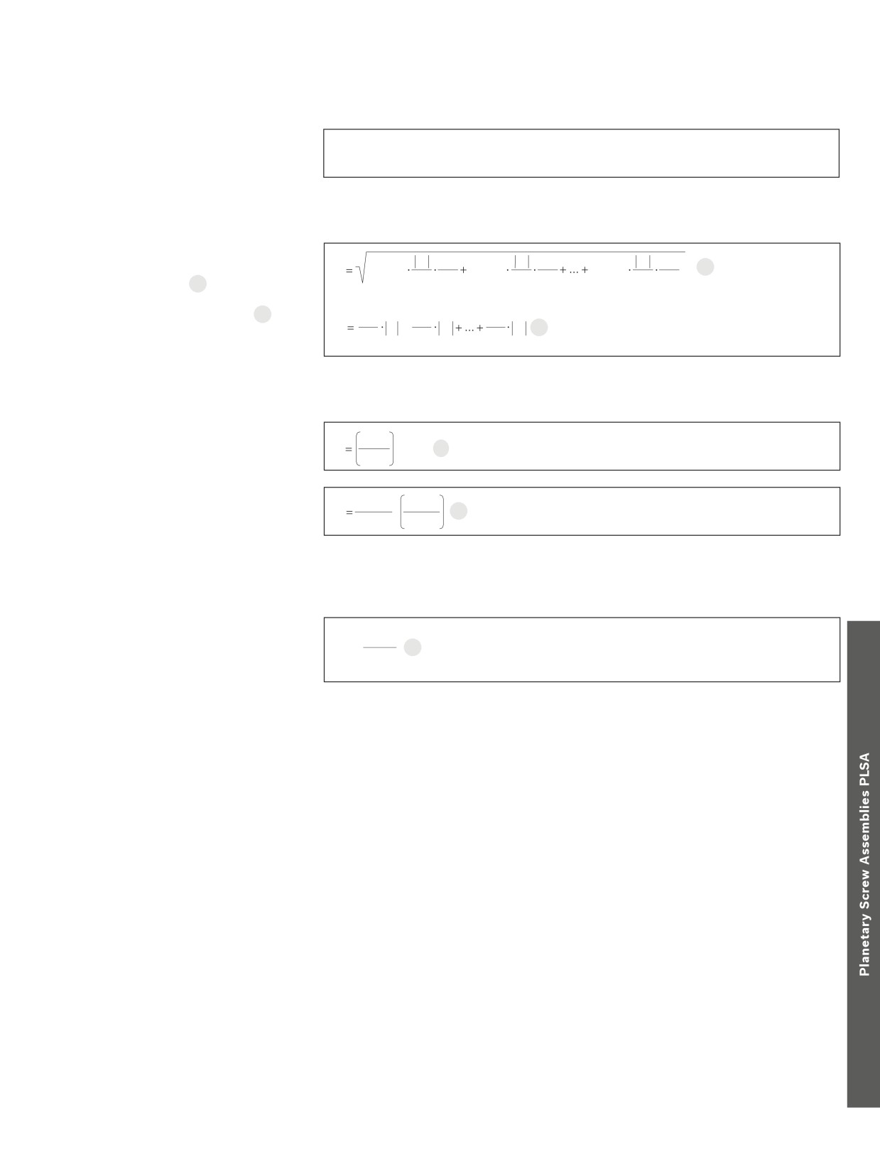
Resulting and equivalent bearing
loads
For angular-contact thrust ball bearings
Fax
= resulting axial
LGN and LGF6
bearing load
(N)
Fcomb = X · Frad + Y · Fax
20
Angular-contact thrust ball bearings are
Fcomb = combined equivalent load
(N)
preloaded. The chart shows the result-
Frad
= radial bearing load
(N)
ing axial bearing load Fax as a function of
preload and axial operating load FLax.
For a purely axial load Fcomb = Fax.
Internal preload limit and resulting bearing load
α = 60°
X
Y
18000
Fax
1.90
0.55
17000
≤ 2.17
Frad
d=50
16000
Fax
0.92
1.00
> 2.17
15000
Frad
14000
d=40
13000
α
= pressure angle
d=301)
12000
Fax
= resulting bearing load
11000
1)
d=25
FLax
= operating load
10000
X, Y
= dimensionless factor
9000
8000
7000
If the radial operating forces are not insig-
6000
d = 35
nificant, the equivalent bearing loads are
d = 30
calculated according to formula 20.
5000
Bearings for Panetary Screw Assemblies are
4000
d = 20
also able to accommodate tilting moments.
3000
d = 17
Limit values
d = 12
The moments that usually occur due to the
2000
weight and drive motion of the screw do not
1000
d = 10
d = 6
generally need to be incorporated into the
2000
4000
6000
8000
10000
12000
14000
16000
18000
calculation of the equivalent bearing load.
Operating load FLax (N)
1) Four row version
cc
Separate technical dimensioning to determine the limit values is absolutely necessary for all attachments (e.g. pillow block
units, bearing assembly, etc.)
Planetary Screw Assemblies PLSA | Screw Assemblies
275
End Bearings
Permissible static axial load for
C0
F0ax p ≤
bearing series LGF
2
The permissible static axial load of LGF
series bearings in screw-down direction is:
The static axial load rating C0 is stated in the Dimension Tables.
Average speed and average bearing load
3
n1
qt1
n2
qt2
qtn
When the bearing load varies in steps over
nn
22
Fm
Fcomb13
Fcomb23
Fcombn3
n
100
100
nm
100
m
nm
a specific period of time 22, calculate the
dynamic equivalent bearing.
When the speed varies, use formula 23. In
qt1
qt2
qtn
n
n1
+
n2
nn
23
these formulas qt
denotes the discrete time
m
100
100
100
steps for the individual phases in %.
Service life and load safety factor
3
C
L
·
106
24
Fcomb
Nominal service life
3
16 666
C
The nominal service life is calculated
L
·
25
h
nm
Fcomb
as follows:
Attention:
take the dynamic load rating of the nut
into account!
Static load safety factor
C0
The static load safety factor for machine
S
0 =
26
tools should not be lower than 4.
F0max
C
= dynamic bearing load rating
(N)
F0ax p
= permissible static axial bearing load
(N)
Fcomb
= combined equivalent load
(N)
Fcomb1 ... Fcombn = combined equivalent axial load in phases 1 ... n
(N)
Fm
= dynamic equivalent bearing load
(N)
L
= nominal service life in revolutions
(-)
Lh
= nominal service life in operating hours
(h)
n1 ... nn
= speeds in phases 1 ... n
(rpm)
nm
= average speed
(rpm)
qt1 ... qtn
= discrete time steps in phases 1 ... n
(%)
276
Screw Assemblies | Planetary Screw Assemblies PLSA
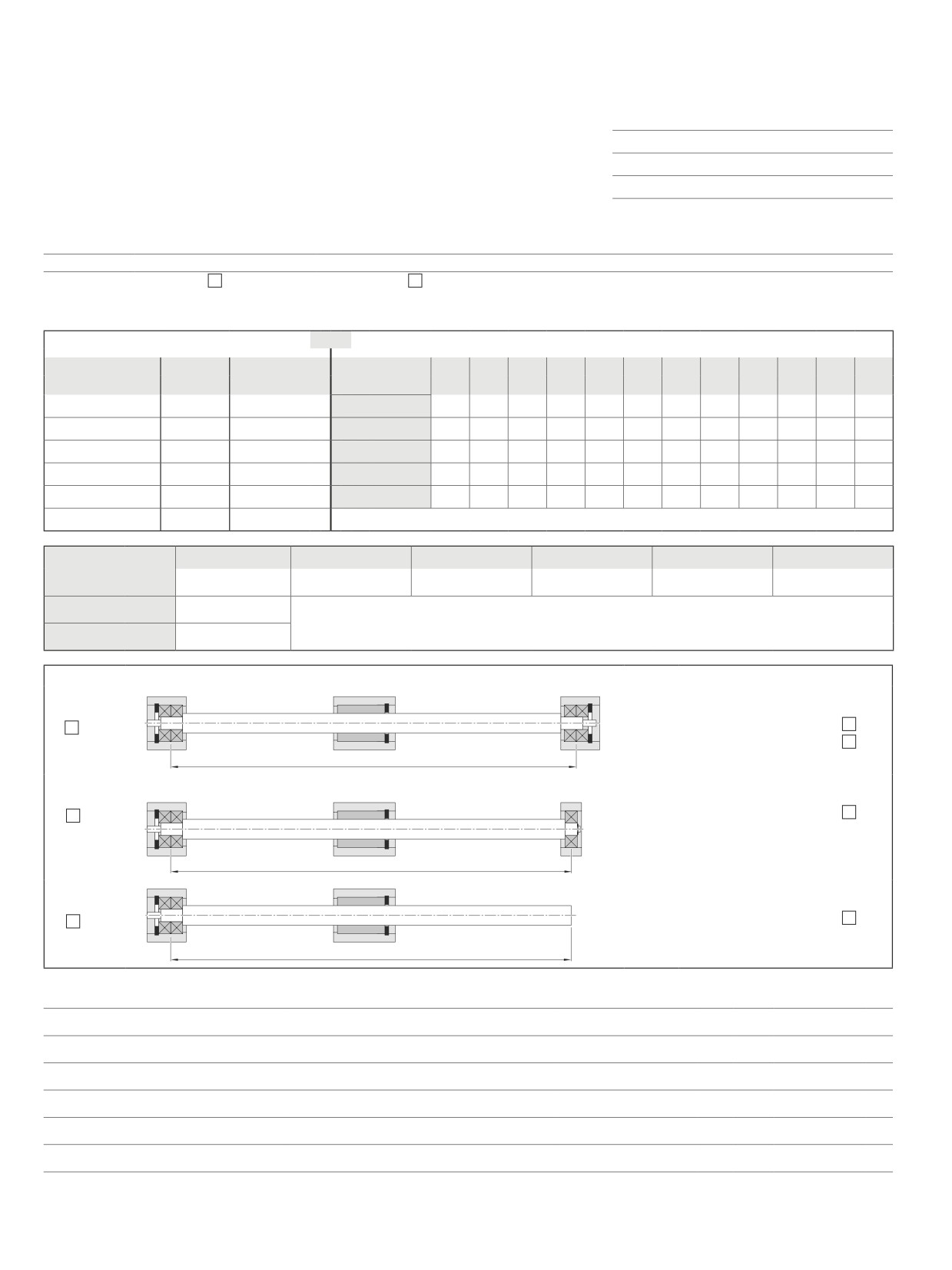
Design Calculation Service Form
Bosch Rexroth
Company:
Linear Motion Technology
Contact:
E-mail:
97419 Schweinfurt / Germany
Telephone:
Find your local contact person here: www.boschrexroth.com/adressen
Application
New design
Revised design
Operating conditions
Discrete time step parameters
or
Dynamic cycle parameters
Discrete time steps
Speed
Action of force x
Section
T1
T2
T3
T4
T5
T6
T7
T8
T9
T10
T11
T12
(%)
(1/min)
T1 =
n1 =
Path
(mm)
T2 =
n2 =
V
(m/s)
T3 =
n3 =
a
(m/s2)
T4 =
n4 =
Time
(s)
T5 =
n5 =
Action of force x
T6 =
n6 =
F1
F2
F3
F4
F5
F6
Forces
(N) =
Mass
(kg) =
Max. stroke
(mm) =
Bearing type
Installation Position
Horizontal
1.
Tight
Tight
Vertikal
Ls
Drawing enclosed
2.
Tight
Loose
(recommended)
Ls
Delivery with bearing
3.
Tight
Free
Ls
Required life:
Operating temperature:
°C Up to
°C
Type of lubrication:
Short description of the application / unusual operating conditions:
Visit out official homepage and use the provided configurators and our dimensioning program Linear Motion Designer free of charge.