HV590 Series Frequency Inverter. User Manual (Version: 3.1.14) - page 3
Section V. Parameter Function Table
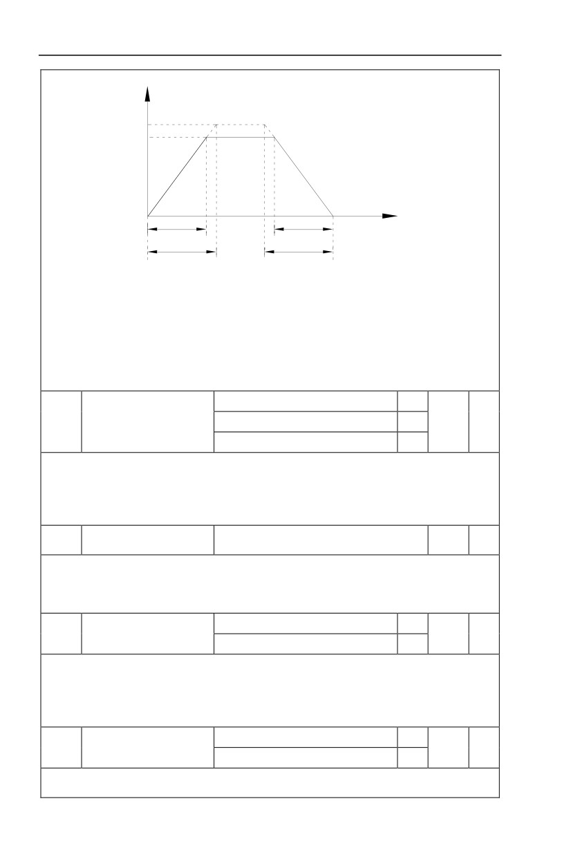
Output frequency
Hz
Acceleraion/deceleration
reference frequency
Setting frequency
t
Actual acceleration time
Actual deceleration time
t1
t2
Setting deceleration time
Setting acceleration time
Fig.5-1Acceleration/decelerationtime schematic diagram
HV590 totally offers 4 groups of speed-up/speed-DOWN time for selection,you can shift through
digital input terminal DI,4 groups of them are shown as follows:
GROUP 1:P0.17、P0.18;
GROUP 2:P8.03、P8.04;
GROUP 3:P8.05、P8.06;
GROUP 4:P8.07、P8.08.
1second
0
P0.19
Acc./dec. time unit
0.1 seconds
1
1
★
0.01 seconds
2
HV590 offers
3 kinds of speed-up
/speed down time unit to meet the need of all kinds of
scene.Respectively for 1 second、0.1 seconds and 0.01 seconds.
Caution:Decimal places as well as corresponding acceleration/deceleration time of the 4 groups may
be changed when modifying this function parameter,special attention should be paid in the process of
application.
Auxiliary frequency source
P0.21
0.00Hz~Maximum frequencyP0.10
0.00Hz
☆
offset frequency
It is valid only at the time of main/auxiliary operation is choosen.
When frequency source is main / auxiliary operation(P0.21 as offset frequency) ,it could make
frequency set more flexible by stacking offset frequency on main& auxiliary operation as the final frequency
set value.
0.1Hz
1
Frequency command
P0.22
2
★
resolution
0.01Hz
2
This parameter is used to dertermine all the function code resolution which is relevant to frequency.
Frequency resolution is
0.1Hz , HV590 maximum output frequency can reach
3200Hz. While
frequency resolution is 0.01Hz, HV590 maximum output frequency is 320.00Hz.
Caution:Parameter (relating to frequency ) decimal digits and corresponding frequency value will
change through modifying P0.22. Special attention should be paid during operation.
Without memory
0
Digital setup frequency
P0.23
0
☆
memory selection upon stop
1
Memory
This function is only valid when frequency source is digital setup.
0: Without memory
48
Section V. Parameter Function Table
Upon power fault or stop of the inverter, set the frequency value back to the setup value of “Preset
Frequency” (P0.08). Frequency modification which set through keyboard “∧”、“∨” or terminal UP、
DOWN is cleared.
1: Memory
Digital setup frequency is the retention that reserved at last stop time. Keyboard “∧”、“∨” or
terminal UP、DOWN to make the correction valid.
Motor 1
0
Motor 2
1
P0.24
Motor selection
0
★
Motor 3
2
Motor 4
3
HV590 support applications that driving 4 motors in time-sharing. 4 motors can be set motor
nameplate parameters, independent parameter tuning, control mode, parameters relating to operation
performance respectively.
Motor 1 corresponding function groups are P1 group and P2 group. Motor 2,motor 3, motor 4
corresponding groups are A2 group, A3 group and A4 group respectively.
Users select current motor through P0.24 function code as well as digital input terminal DI. When
function code selecton conflicting with terminal DI selection, DI terminal selection is priority.
Maximum frequency(P0.10)
0
Acceleration / deceleration
P0.25
Set frequency
1
0
★
reference frequency
100Hz
2
Acceleration / deceleration time means the time needed for the inverter varying from 0Hz to the
frequency ofP0.25, Fig5.1 is acceleration / deceleration time schematic diagram.
When P0.25 is choosen to 1, acceleration / deceleration time is connected with set frequency.If set
frequency change frequently, the motor acceleration willchange,attention should be paid in applications.
Running frequency
0
Frequency UP/DOWN
P0.26
0
★
reference upon running
Set frequency
1
This parameter is only valid when frequency source is digital setting.
To select(through keyboard
∧、∨ key or terminal UP/DOWN) the modifying method of set
frequency, namely, target frequency is increasing/decreasing based on the running frequency or setting
frequency.
The difference between the two settings become apparently in inverter acceleration and
deceleration process.
Operation panel command bound
1bit
frequency source selection
Without binding
0
Digital setup frequency source
1
AI1
2
Command source &
AI2
3
P0.27
000
☆
frequency source binding
AI3(Potentiometer)
4
PULSE pulse setup(DI5)
5
MS command
6
Simple PLC
7
PID
8
49
Section V. Parameter Function Table
Communication setup
9
Terminal command bound frequency
10bit
source selection
Without bound
0
Digital setup frequency source
1
AI1
2
AI2
3
AI3(Potentiometer)
4
PULSE pulse setup(DI5)
5
MS command
6
Simple PLC
7
PID
8
Communication setup
9
Communication command binding
100bit
frequency source selection
Without bound
0
Digital setup frequency source
1
AI1
2
AI2
3
AI3(Potentiometer)
4
PULSE pulse setup(DI5)
5
MS command
6
Simple PLC
7
PID
8
Communication setup
9
It defines bound combination between
3 running command channels and 9 frequency setup
channels, which is easy to achieve synchronous switching.
Frequency setup channels above have the same definition with P0.03 “main frequency source X
selection”, please refer to P0.03 for details. Different running command channels can bind the same
frequency setup channel. When the command source is valid during command source & frequency
source binding, set frequency source of P0.03~P0.07 is invalid.
Modbus communication card
0
Profibus.DP communication card
1
Communication expansion
P0.28
0
☆
card
CANopen communication card
2
CANlink communication card
3
HV590 series offers 3 kinds of communication mode. All of the 3 need to be equipped with optional
communication card .And they can not be used at the same time.
P0.28 is used to set the type of the optional communication card. When user replace the
communication card , P0.28 should be properly set.
50
Section V. Parameter Function Table
5.3 Parameters for motor 1:P1.00-P1.37
FactoryChange
Code
Description/Display
Setting Range
Setting
Limit
General asynchronous motor
0
P1.00
Motor type selection
Variable frequency asynchronous motor
1
0
★
P1.01
Rated power
0.1kW~1000.0kW
-
★
P1.02
Rated voltage
1V~2000V
-
★
0.01A~655.35A(Inverter power≦55kW)
P1.03
Rated current
-
★
0.1A~6553.5A(Inverter power >55kW)
P1.04
Rated frequency
0.01Hz~maximum frequency
-
★
P1.05
Rated revolving speed
1rpm~65535rpm
-
★
Function codes above are motor nameplate parameters. No matter VF control or vector control is the
choosen mode, users should accurately set the relating parameter according to the motor nameplate.
For better VF or vector control performance, users should tune the motor parameter. The accuracy of
the regulation results has intimate relationship with the accuracy of set motor nameplate parameters.
Asynchronous motor stator
0.001Ω~65.535Ω(Inverter power <=55kW)
P1.06
-
★
resistance
0.0001Ω~6.5535Ω(Inverter power >55kW)
Asynchronous motor rotor
0.001Ω~65.535Ω(Inverter power <=55kW)
P1.07
-
★
resistance
0.0001Ω~6.5535Ω(Inverter power >55kW)
Asynchronous motor
0.01mH~655.35mH(Inverter power <=55kW)
P1.08
-
★
leakage inductance
0.001mH~65.535mH(Inverter power >55kW)
Asynchronous motor mutual
0.1mH~6553.5mH(Inverter power <=55kW)
P1.09
-
★
inductance
0.01mH~655.35mH(Inverter power >55kW)
Asynchronous motor no
0.01A~P1.03(Inverter power <=55kW)
P1.10
-
★
load current
0.1A~P1.03(Inverter power >55kW)
P1.06~P1.10 are parameters for asynchronous motor.Generally, motor nameplate dosen’t contain
such parameters, users can get them throung inverter auto tuning. Among them,
3 parameters
(P1.06~P1.08) can be get through “ asynchronous motor static tuning”, while all the 5 parameters as well
as encoder phase ,current loop PI etc can be get through“asynchronous motor complete tuning”. When
change the motor rated power (P1.01) or motor rated voltage (P1.02), inverter would automatically
modify the P1.06~P1.10 parameter value and restore them to common standard of Y series motor
parameter.
If the asynchronous motor is unable to be tuned, users could input above parameters with factory
offeredmotor value.
P1.27
Encoder pulses number
1~65535
2500
★
To set ABZ or UVW incremental encoder pulse number per revolution.
In the speed sensor vector control mode, P1.27 must be set accurately.Or motor would not normally
operate.
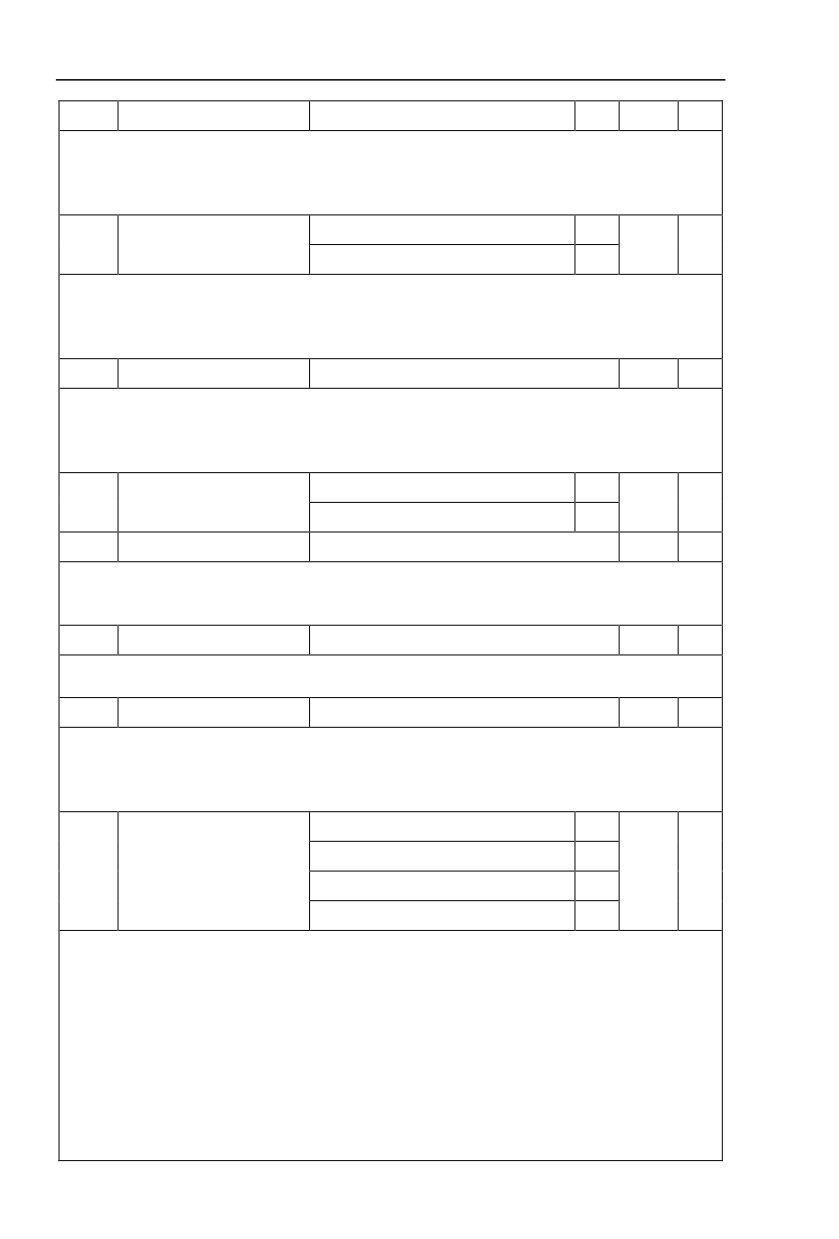
ABZ incremental encoder
0
UVW incremental encoder
1
P1.28
Encoder type
0
★
Rotary transformer
2
Sine/cosine encoder
3
51
Section V. Parameter Function Table
UVW encoder
4
HV590 support multiple encoder types. Different encoder should be equipped with different PG card.
For specifications please refer to Appendix IV. All the 5 encoders are suitable for synchronous motor,
while only ABZ incremental encoder and rotary transformer are suitable for asynchronous motor.
After installing the PG card, make sure that P1.28 is accurate according to actual situation.
Forward
0
ABZ incremental encoder AB
P1.30
0
★
phase
Reserve
1
This function code is only valid to ABZ incremental encoder(P1.28=0).It is used to set ABZ
incremental encoder AB signal phase sequence.
It is valid for both synchronous motor and asynchronous motor. Users could get ABZ encoder AB
phase sequence through asynchronous motor complete tuning or synchronous motor no-load tuning.
P1.31
Encoder installation angle
0.00~359.90
0.00
★
This parameter is only valid to synchronous motor control mode. It is valid for encoder types of ABZ
incremental encoder, UVW incremental encoder, rotary transformer,and UVW encoder.
P1.31 is available for synchronous motor complete / static tuning .It’s very important to operation of
synchronous motor. User should tune it before synchronous motor initial use.
Forward
0
P1.32
UVW phase sequence
0
★
Reverse
1
P1.33
UVW encoder offset angle
0.00~359.90
0.00
★
P1.32 and P1.33 are only valid for synchronous motor using UVW encoder.
These two parameters can be obtained through synchronous motor complete / static tuning, which are
very important to operation of synchronous motor. Users should tune them before synchronous initial use.
P1.34
Rotary transformer pole pairs
1~65535
1
★
Rotary transformer is equipped with pole pairs.When using the encoder, correct parameters must be
set to it.
P1.36
PG dropped inspection time
0.0s:no action
0.1s~10.0s
0.0s
★
It is used to set inspection time of encoder disconnection fault.When feedback signal is
0.0s,
encoder disconnection fault will not be inspected.
If inverter detected disconnection fault,and the feedback value exceeded the P1.36 setup
range.Inverter fault alarm No. 20= E.PG1.
Without operation
0
Asynchronous static tuning 1
1
P1.37
Tuning selection
0
★
Asynchronous complete tuning
2
Asynchronous static tuning 2
3
Caution:Correct motor ratings must be set before tuning
0:No operation, tuning is forbidden.
1:Asynchronous motor static tuning 1
It is used for occasions that asynchronous motor and the load are not easily torn off, which may lead
to complete tuning invalid. Correct motor type and motor nameplate parameters P1.00~P1.05 must be
set before static tuning. User could get P1.06~P1.08 through tuing.
Action description:Set P1.37 to 1 and then press RUN button, inverter will carry out asynchronous
static tuning.
2:Asynchronous complete tuning
Asynchronous complete tuning can guarantee inverter dynamic control performance. Motor and the
load should be disconnected to keep motor complete status.
52
Section V. Parameter Function Table
In the process of asynchronous complete tuning , asynchronous complete tuning is taken first, and
then accelerate to 80% of motor rated frequency according to P0.17. After keeping the state for a period
of time, then decelerate to stop according to P0.18 and stop tuning.
Before asynchronous complete tuning
, users should set motor type and motor nameplate
parameters P1.00~P1.05 as well as encoder type and encoder pulse numbers P1.27、P1.28.
Inverter can get 5 motor parameters P1.06~P1.10 as well as AB phase sequence P1.30, vector
control current loop PI parameter P2.13~P2.16 from tuning.
Action description:Set P1.37 to 2 and then press RUN button, inverter will carry out asynchronous
complete tuning.
3:Asynchronous motor static tuning
It is used for no encoder
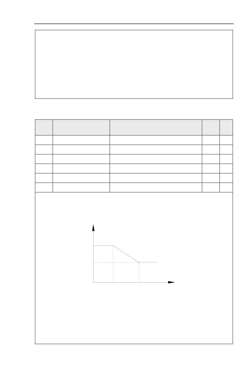
5.4 Vector control function group:P2.00-P2.22
P2 group function codes are valid for vector control and invalid for V/F control.
FactoryChange
Code
Description/Display
Setting Range
Setting
Limite
P2.00
Speed loop proportional gain1
1~100
30
☆
P2.01
Speed loop integration time1
0.01s~10.00s
0.50s
☆
P2.02
Switching frequency1
0.00~P2.05
5.00Hz
☆
P2.03
Speed loop proportional gain 2
0~100
20
☆
P2.04
Speed loop integration time 2
0.01s~10.00s
1.00s
☆
P2.05
Switching frequency 2
P2.02~maximum frequency
10.00Hz
☆
Users could choose different speed loop PI parameters under different running frequency. When
running frequency is less than the switching frequency(P2.02), adjusting parameters for speed loop PI are
P2.00 and P2.01. When running frequency is greater than the switching frequency (P2.02), adjusting
parameters for speed loop PI are P2.03 and P2.04. Speed loop PI parameters between switching
frequency1 and switching frequency2 are two groups of linear switching. As shown in fig.5.2:
PI parameter
P2.00
P2.01
P2.03
P2.04
P2.02
P2.05
Frequency command
Fig.5-2PI parameter schematic diagram
Users can adjust vector control speed dynamic response characteristics through setting proportional
coefficient and integration time of the speed regulator.
Both increasing proportional gain and reducing integration time can accelerate the speed loop
dynamic response.But excessive proportional gain or insufficient integration time may led to system
oscillation.
Suggestions for regulating method:
If the factory parameters can not meet the requirements, users can fine-tuning it on the basis of factory
value parameters. First increase the proportional gain to restrain system oscillation,then
53
Section V. Parameter Function Table
reduceintegrationtime so that system has fast response characteristic and smaller overshoot.
Notice:Improper PI parameter setting may lead to excessive speed overshoot , even voltage fault
during overshoot drop.
P2.06
Vector control slip gain
50%~200%
100%
☆
This parameter is used to adjust motor steady speed precision for zero-speed sensor vector control
mode. Please turn up the parameter value when with load motor running in low speed. On the contrary,
when the with load motor running in high speed, please turn down the parameter value.
This parameter is also used to adjust the output current value with the same load for speed sensor
vector control.
P2.07
Speed-loop filter time
0.000s~0.100s
0.000s
☆
In vector control mode, speed-loop regulator outputs torque current command. P2.07 is used to filter
the torque command.
Generally speaking, the parameter needs not to be modified. Users could properly increase the
filtering time when speed fluctuation is relatively big, and decrease the value when motor oscillation occurs.
If filtering time is small, inverter output torque might fluctuate greatly, but response speed will be fast.
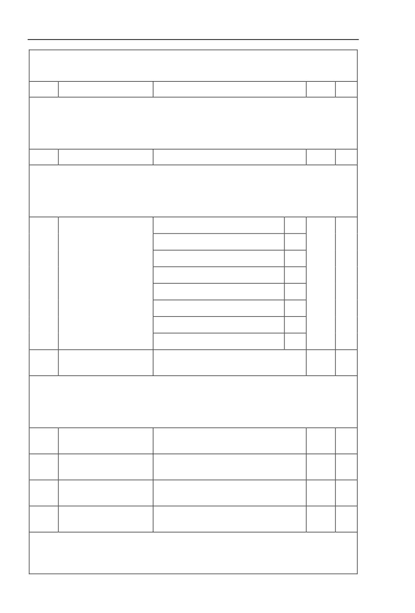
P2.10
0
AI1
1
AI2
2
AI3(Potentiometer)
3
Torque upper limit source in
P2.09
0
☆
speed control mode
PULSE setup
4
Communication setup
5
Min(AI1,AI2)
6
Max(AI1,AI2)
7
Torque upper limit digital setup
P2.10
0.0%~200.0%
150.0%
☆
in speed control mode
In speed control mode, inverter maximum torque output is controlled by torque upper limit.
Range for 1-7 selections of P2.09 are corresponding to the setting range of P2.10.
P2.09 is used to select torque upper limit source. When P2.09 is set through analog, PULSE setup,
communication setup, which 100% corresponding to P2.10. 100% of P2.10 is the rated torque of the
inverter.
Excitation regulation
P2.13
0~20000
2000
☆
proportional gain
Excitation regulation
P2.14
0~20000
1300
☆
integration gain
Torque regulation
P2.15
0~20000
2000
☆
proportional gain
Torque requlation integration
P2.16
0~20000
1300
☆
gain
Vector control current-loop PI regulation, which is automatically obtained after asynchronous motor
complete tuning or synchronous motor complete tuning. It generally needs not to be modified.
Caution:Integration regulator of current loop directly set integration gain without taking integration
time as the dimension. Excessive current loop PI gain may lead oscillation to the entire control loop circuit.
54
Section V. Parameter Function Table
If current oscillation or torque fluctuation is relatively big, users could manually turn down the PI
proportional gain or integration gain.
5.5 V/F control group:P3.00-P3.15
This function group is only valid for V/F control mode.
V/F control is suitable for general load such as draught fan, pump. It is also appropriate for
situations where one inverter driving multiple motors or there is big difference between inverter
power and motor power.
FactoryChange
Code
Description/Display
Setting Range
Setting
Limite
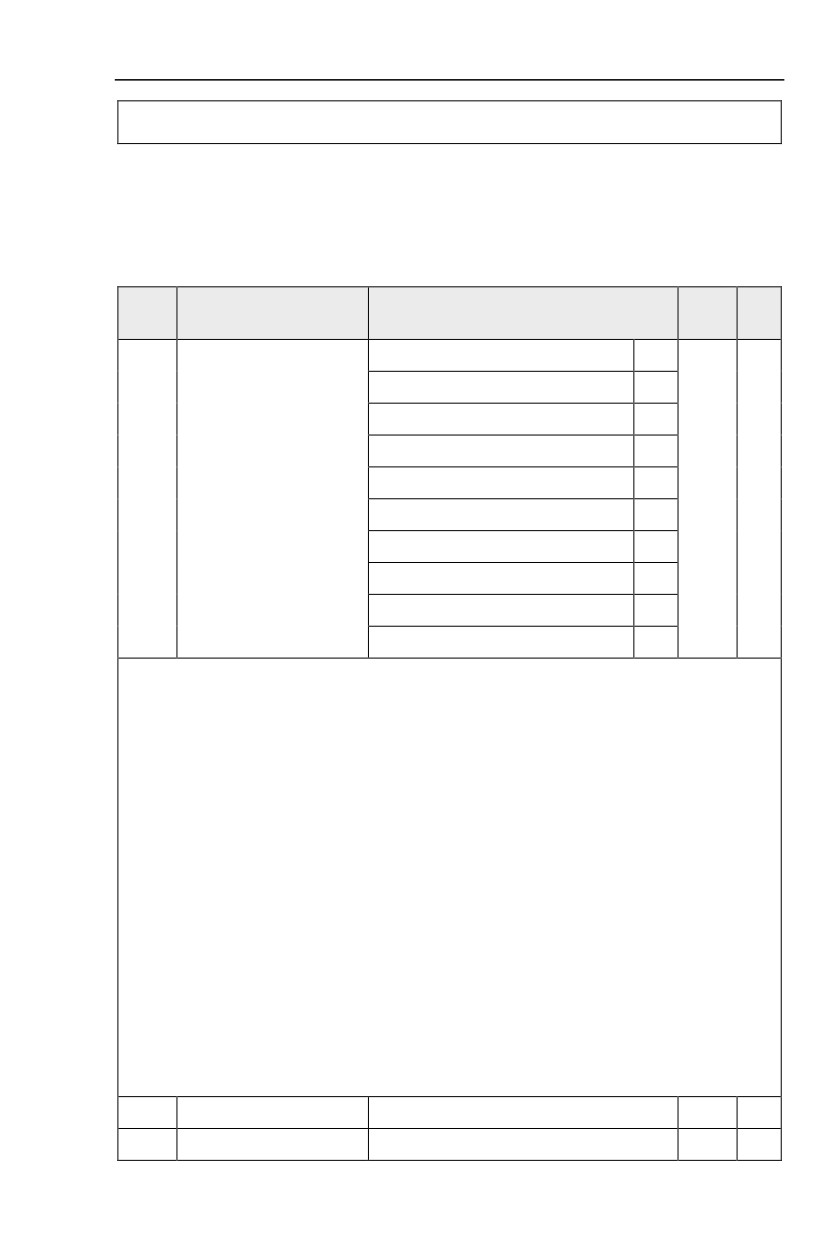
Beeline V/F
0
Multi-point V/F
1
Square V/F
2
Power of 1.2 V/F
3
Power of 1.4 V/F
4
P3.00
V/F curve setup
0
★
Power of 1.6 V/F
6
Power of 1.8 V/F
8
Reserved
9
VF complete separation mode
10
VF semi separation mode
11
This parameter defines the V/F setup mode so as to meet the requirements of various load characteristics.
0:Beeline V/F
It is suitable for the ordinary constant torque load.
1:Multi-point V/F
It is suitable for special loads such as dehydrator and centrifugal machine. It can be self-defined.
Refer to the description of functional codes of Group F1-07 to F1-12 for details.
2:Square V/F
It is suitable for centrifugal loads such as fan and pump.
3~8:These are relation curve situated between beeline V/F curve and square V/F curve.
9:Reserved
10:VF complete separation mode
Inverter output frequency and output voltage are mutually independent. Output frequency is decided
by frequency source,while output voltage is decided by P3.13(VF separation voltage source).
VF complete separation mode is generally applied in induction heating, inverter power supply, torque
motor control fields etc.
11:VF semi separation mode
In this case, V is proportional to F. Proportional relationship can be set by the voltage source
P3.13. The relationship between V&F is connected with P1 group(motor rated voltage and rated
frequency).
Suppose that voltage source input is X (X from 0~100%), the V,F relationship is:
V/F=2*X*(Motor rated voltage)/(Motor rated frequency)
P3.01
Torque boost value
0.0%~30%
-
★
P3.02
Torque boost cut-off frequency
0.00~Maximum frequency
50.00Hz
★
55
Section V. Parameter Function Table
Output voltage
Vb
V1
f1
fb
Output frequency
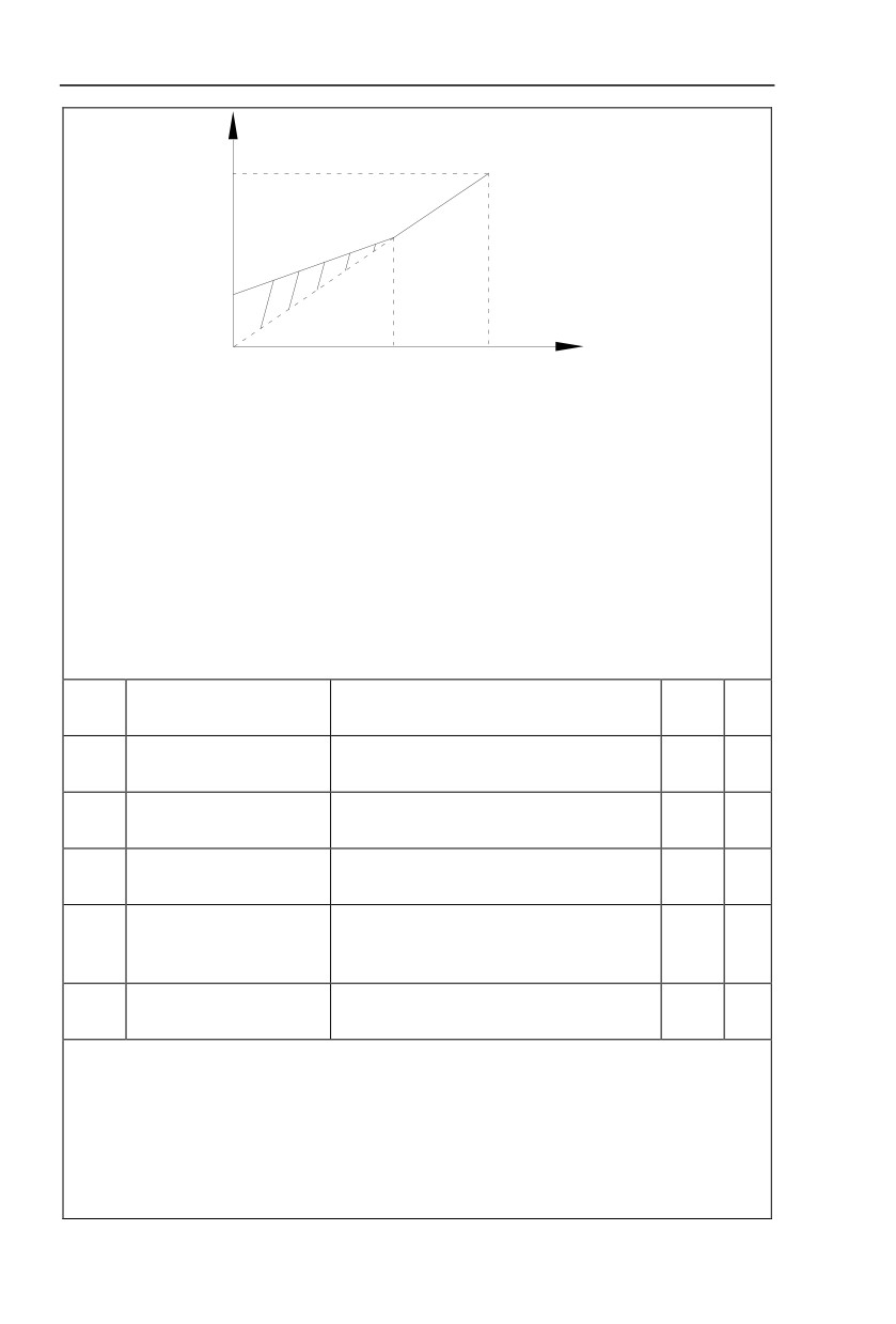
V1:Manual torque boost voltage
Vb:Maximum output voltage
f1:Cutt-off frequency of torque boost fb:Rated running frequency
Fig. 5-3 Manual torque boost schematic diagram
To compensate the low frequency torque characteristics of V/F control, boost compensation should be
made to inverter low frequency output voltage.
Torque hoist: it will be set according to the percentage of input rated voltage to the inverter. Below
are explanations of setting torque increase:
1) When the torque hoist is set as 0.0%, the inverter will aYpt auto torque hoist.
2) This parameter can be properly hoisted for small motor, while for large motor; the parameter can be
properly decreased.
3) If the torque hoist is set to be too large, the motor may be overheated, and the inverter may be
over-current.
Torque hoist cut-off frequency: As shown in Fig. 5.3, the torque hoist is valid when the cutoff
frequency below this setting. Otherwise, the torque hoist will be invalid.
Multi-point V/F frequency
P3.03
0.00Hz~P3.05
0.00Hz
★
point F1
Multi-point V/F voltage point
P3.04
0.0%~100.0%
0.0%
★
V1
Multi-point V/F frequency
P3.05
P3.03~P3.07
0.00Hz
★
point F2
Multi-point V/F voltage point
P3.06
0.0%~100.0%
0.0%
★
V2
P3.05~Motor rated frequency(P1.04)Note:Motor
Multi-point V/F frequency
P3.07
2\3\4 rated frequency respectively
0.00Hz
★
point F3
A2.04\A3.04\A4.04
Multi-point V/F voltage point
P3.08
0.0%~100.0%
0.0%
★
V3
Six parameters of P3.03 to P3.08 define the multi-point V/F curve.
The setup value of multi-point V/F curve is generally set in accordance with the load characteristics of
the motor.
Caution:
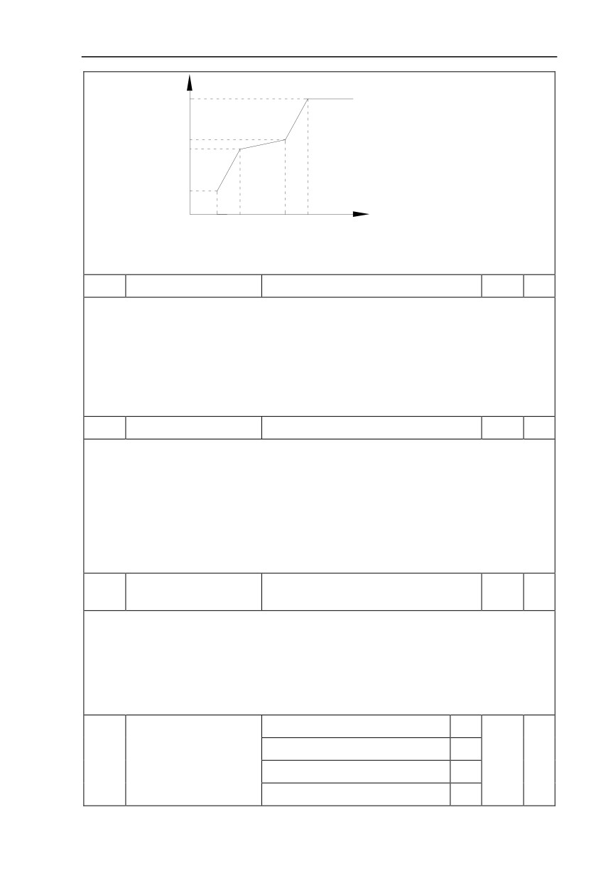
1) It must be set as follows: V1<V2<V3,F1<F2<F3. Fig5.4 is schematic diagram for multi-point
V/F curve.
2) If the voltage is set too high at the time of low frequency, it may cause overheating and even
burning of the motor as well as stall over current or over current protection of the inverter.
56
Section V. Parameter Function Table
Voltage %
Vb
V3
V2
V1
F1
F2
F3
Fb
Frequency %
V1-V3:MS speed V/F 1~3 segment
F1-F3:MS speed V/F 1~3 segment
voltage proportion
frequency proportion
Vb:Rated motor frequency
Fb:Rated motor running frequency
Fig. 5-4 Multi-point V/F curve setup schematic diagram
P3.09
V/F slip compensation gain
0%~200.0%
0.0%
☆
This parameter is only valid for asynchronous motor.
VF slip compensation can compensate asynchronous motor speed deviation ,in this way ,motor rotary
speed could be maintained in basically stable state during load change. In general, 100% corresponds to
the rated slip of the motor with rated load. For motor rated slip , it can be get through auto calculation of P1
motor rated frequency and rated revolving speed.
The slip compensation gain adjustment may be performed referring to the following principle: When
the load is rated load, and the slip compensation coefficient is set to 100%, the rotary speed of the motor is
close to the reference speed.
P3.10
VF over-excitation gain
0~200
64
☆
The role of over excitation gain function is to suppress the rise of bus voltage during the inverter
deceleration process, thus avoiding occurrence of over voltage fault due to bus voltage exceeding over
voltage protection limitation value. The higher the over excitation gain is, more powerfully the suppression
effect is. The setting is described as follows:
In the applications where over-voltage alarm easily occurs, it needs to improve the over-excitation
gain. Excessive over-excitation gain easily lead to increasing of output current .Users should keep the
balance during operation.
In the applications where the inertia is very low, the over excitation gain is set to 0, while in the
applications where there is brake resistor ,the over excitation gain is set to 0 as well.
VF oscillation suppression
P3.11
0~100
-
☆
gain
When the motor has no oscillation, please select this gain to 0. Only when the motor has obvious
oscillation and Yes not run normally can the gain be properly increased. The bigger the gain is, the better
oscillation suppression result will be.
The gain shall be set as small as possible under the condition that the oscillation is suppressed
effectively so as to avoid high influences on the V/F operation.
Accurate motor rated current and no-load current parameters are required during using oscillation
suppression function, or VF oscillation suppression effect will not be excellent.
Digital setup(P3.14)
0
AI1
1
P3.13
VF separation voltage source
0
☆
AI2
2
AI3(Potentiometer)
3
57
Section V. Parameter Function Table
PULSE pulse setup(DI5)
4
MS command
5
Simple PLC
6
PID
7
Communication setup
8
100% corresponding to the rated motor voltage (P1.02、A4.02、
A5.02、A5.02)
VF separation voltage digital
P3.14
0V~rated motor voltage
0V
☆
setup
VF separation is generally applied to induction heating control, inverter power supply control and
torque motor control etc.
In VF separation control mode, output voltage can be set through function code P3.14, analog value,
MS command , PLC, PID or communication setup.
When P3.13 is nonnumeric setup, each 100% of the setting corresponds to rated moter voltage. When
output setting percentage is negative, it’s absolute value is the valid setting value.
0:Digital setup(P3.14)
Voltage is directly set through P3.14.
1: AI1
2: AI2
3:AI3(Potentiometer)
Voltage is set through analog input terminal.
4: PULSE pulse setup(DI5) voltage set through terminal pulse.
Pulse setup signal specification:voltage range 9V~30V, frequency range 0kHz~100kHz.
5: MS command voltage source is MS command.
Corresponding relationship between set signal and set voltage is determined through
P4 group and PC group.
6: Simple PLC
When voltage source is simple PLC, output voltage is set through PC group parameters.
7: PID
Output voltage through PID closed loop.For specifications please refer to PA group for PID detailed
description.
8:Communication setup
Communication setup refers to voltage that set by position machine through communication mode.
When the above voltage source selection is 1~8, 0~100% corresponds to output voltage 0V~motor
rated voltage.
VF separation voltage rise
P3.15
0.0s~1000.0s
0.0s
☆
time
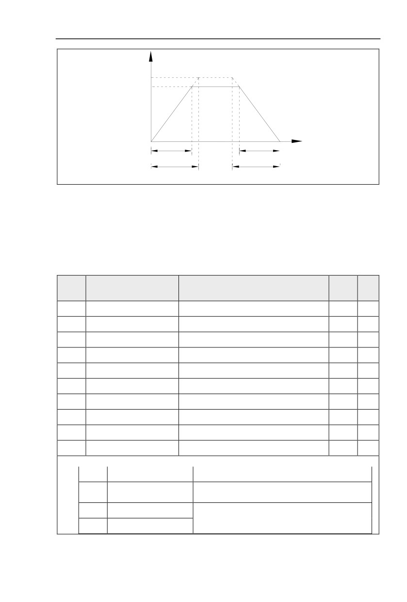
P3.15 refers to the time that needed for output voltage varying from 0V to motor rated voltage.As
shown in fig.5-5.
58
Section V. Parameter Function Table
Output voltage V
Rated motor voltage
Output voltage target value
t
Actual voltage rise time
Actual voltage fall time
Setting voltage rise time
Setting voltage fall time
Fig. 5-5 VF separation schematic diagram
5.6 Input terminal:P4.00-P4.40
HV590 series inverter has 6 multifunctional digital input terminals (DI1 to DI6), of which DI5
can be used as high-speed pulse input terminal, and HV590 series inverter also has 2 analog
input terminals.If system needs more input/output terminal, it can be equipped with multi-
function input/output expansion card and 1 analog input terminal(AI3x).
Multi-function input/output expansion card has
4 multi-function digit input
terminal(DI7~DI10).
FactoryChange
Code
Description/Display
Setting Range
Setting
Limite
P4.00
DI1terminal function selection
0~59
1
★
P4.01
DI2 terminal function selection
0~59
4
★
P4.02
DI3 terminal function selection
0~59
9
★
P4.03
DI4 terminal function selection
0~59
12
★
P4.04
DI5 terminal function selection
0~59
13
★
P4.05
DI6 terminal function selection
0~59
2
★
P4.06
DI7 terminal function selection
0~59
12
★
P4.07
DI8 terminal function selection
0~59
13
★
P4.08
DI9 terminal function selection
0~59
14
★
P4.09
DI10 terminal function selection
0~59
15
★
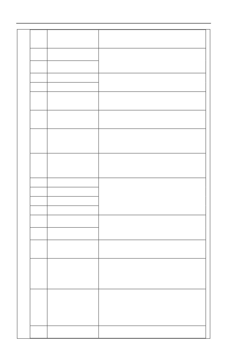
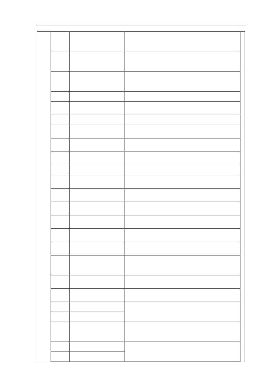
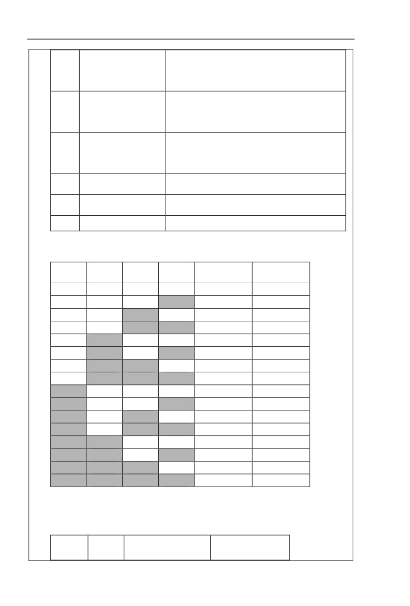
These parameters are used to set digital multi-function input terminals, as shown in the table below:
Setting
Function
Specification explanation
Set useless terminals to “no function”, in order to prevent
0
No- function
misoperation.
1
Forward command (FWD)
The forward jog and reverse jog of the inverter are
controlled via the external terminals.
2
Reverse command (REV)
59
Section V.
Parameter Function Table
Set inverter running mode as three line control mode.For
3
Three line running control
details please refer to function code P4.11(Terminal
command mode).
FWD JOG
4
FJOG refers to jog forward running, RJOG refers to jog
command(FJOG)
reverse running. For jog running frequency, jog acc./dec.
REV JOG
5
time please refer to P8.00、P8.01、P8.02 for details.
command(RJOG)
6
Up command
When command source is set as “Digital Setup”, the
increase or decrease of the set frequency is implemented
7
DOWN command
through the external terminal.
When this terminal command is valid, meaning that the
8
Free stop
inverter locks the output, the load will free stop according
to the mechanical inertia.this way is the same withP6.10
When this terminal command is valid, inverter’s fault can
9
Fault reset(RESET)
be reset. It has the same function with RESET key on the
keyboard.This function can realize remote fault reset.
Inverter decelerates to stop, but all operation parameters
are memorized. E.g : PLC parameter, swing frequency
10
Operation suspended
parameter, PID parameter. When this terminal signal
disappeared, inverter restored to running status as before.
When the inverter detects that the signal occurs , it will
External default normally
report “15=Err15” fault, and handle the fault according to
11
open input
the fault protection action mode.(Please refer to P9.47 for
details).
12
Multi-stage speed terminal1
13
Multi-stage speed terminal2
The setting of 16-segment speeds can be realized by the
combinations of the terminal status when the frequency
14
Multi-stage speed terminal3
source is “MS Speed”. Refer to schedule 1 for details.
15
Multi-stage speed terminal4
Acc./dec.time selection
16
It can realize 4 kinds of acc./dec. selection mode by 4
terminal 1
combination status of this 2 terminals.For details please
Acc./dec.time selection
17
refer to schedule2.
terminal 2
It is used to switch to choose different frequency sources.
18
Frequency source switching
It realizes switching between
2 kinds of frequency
sources according to the setup of P0.07.
When the frequency source is given as “Digital Setup”
UP/DOWN setup
and the terminal command is valid, it can clear the
19
reset(terminal and
frequency values changed through keyboard or terminals
keyboard)
UP/DOWN and restore the reference frequency to the
setup value of “Preset Frequency"( P0.08).
When command source is set to terminal control
(P0.02=1), the terminal could realize switching between
Running command
terminal control and keyboard control.
20
switching terminal
When command source is set to communication
control(P0.02=2), the terminal could realize switching
between communication control and keyboard control.
When this terminal command is valid, it can maintain the
21
Acc./dec forbidden
current frequency output while stopping.
60
Section V.
Parameter Function Table
PID temporary invalid, the inverter maintains the current
22
PID pause
frequency output and no longer taking PID adjustment of
frequency source.
When this terminal command is valid, it clears the
23
PLC status reset
memorized PLC running phase and running time, and
restores to the initial status of PLC running.
When this terminal command is valid, the inverter maintains
24
Swing frequency pause
the frequency output of the swing frequency center, and the
swing frequency pauses.
25
Counter input
It is used as input terminal of the counting pulse.
When this terminal command is valid, it clears the
26
Counter reset
counting value of the counter to zero.
27
Length counting input
It is used as pulse input terminal of the length counting.
When this terminal is valid, it clears the length counting to
28
Length counting reset
zero.
It prohibits inverter torque control. Inverter enters in
29
Torque control forbidden
speed control mode.
PULSE
frequency
30
DI5 is used as pulse input terminal.
input(Only valid for DI5)
31
Reserved
Reserved
When this terminal is valid, inverter directly switch to dc
32
Immediate DC braking
braking state.
External default normally
When the inverter detects that the signal occurs , it will
33
closed input
report “Err15” fault, and stop running.
Frequency modification
If the function is valid, inverter Yes not respond to
34
enable
frequency change until the function turns to be invalid.
PID and PA.03 set values are set in oppoisite directions
35
PID direction reversed
when the terminal is valid.
It could make inverter stop when in keyboard control.
36
External stop terminal1
Equivalent to function of STOP key on the keyboard.
Control command
It is used to switch control mode between terminal and
37
switching terminal 2
communication.
When it is valid, PID integration regulation function pauses,
PID
integration
38
while PID proportional regulation and differential regulation
suspension
function are still valid.
Frequency source X and
When it is valid, frequency source X is replaced by the
39
preset frequency switching
preset frequency P0.08.
Frequency source Y and
When it is valid, frequency source Y is replaced by the
40
preset frequency switching
preset frequency P0.08.。
41
Motor selection terminal1
It can realize 4 groups of motor parameters switching by 4
combination status of this 2 terminals.For details please
42
Motor selection terminal2
refer to schedule3.
PA.18=1, the parameter is invalid, PID parameter takes
43
PID parameter switching
use of PA.05~PA.07. On the contrary, PA.15~PA.17 are
taken for the use.
When user-defined fault 1&2 are valid, inverter alarm fault
44
User-defined fault 1
number 27= E.USt1 & 28= E.USt2 respectively. Inverter will
45
User-defined fault 2
handle the fault according to the mode selected by P9.49.
61
Section V. Parameter Function Table
It enables control mode to switch between inverter torque
Speed control/ torque
control and speed control. Inverter running in the A0.00
46
control switching
defined mode when the terminal is invalid, and will switch
to another mode when it is valid.
Inverter stops at the fastest speed when the terminal is
valid. Current is set to the current upper limit during this
47
Emergency stop
stop process. This function is used for inverter fast stop ,
which can meet the stop need in system emergency.
This terminal can be used to stopthe inverter in any
circumstances
(panel control
,terminal control and
48
External stop terminal 2
communication control). Deceleration time is fixed to
deceleration time 4.
If it is valid, inverter first decelerates to stop DC braking
49
Deceleration DC braking
start frequency and then switches to DC braking state.
Inverter running time of this time is cleared if the terminal is
50
Running time reset
valid. It operates with the use of P8.42 and P8.53.
51-59
Reserved
Reserved
Schedule 1 MS command function description
4 MS command terminals, which can be combined into 16 states. For 16 corresponding values, please
refer to schedule 1 as below:
Corresponding
K4
K3
K2
K1
Command setup
parameter
OFF
OFF
OFF
OFF
MS command 0
PC.00
OFF
OFF
OFF
ON
MS command 1
PC.01
OFF
OFF
ON
OFF
MS command 2
PC.02
OFF
OFF
ON
ON
MS command 3
PC.03
OFF
ON
OFF
OFF
MS command 4
PC.04
OFF
ON
OFF
ON
MS command 5
PC.05
OFF
ON
ON
OFF
MS command 6
PC.06
OFF
ON
ON
ON
MS command 7
PC.07
ON
OFF
OFF
OFF
MS command 8
PC.08
ON
OFF
OFF
ON
MS command 9
PC.09
ON
OFF
ON
OFF
MS command 10
PC.10
ON
OFF
ON
ON
MS command 11
PC.11
ON
ON
OFF
OFF
MS command 12
PC.12
ON
ON
OFF
ON
MS command 13
PC.13
ON
ON
ON
OFF
MS command 14
PC.14
ON
ON
ON
ON
MS command 15
PC.15
When frequency source is set to multi-stage speed mode, 100.0% of function code PC.00~PC.15 are
corresponding to maximum frequency P0.10. To meet the need, MS command can be used not only for
multi-stage speed function, but also PID setup source or VF separation voltage source.
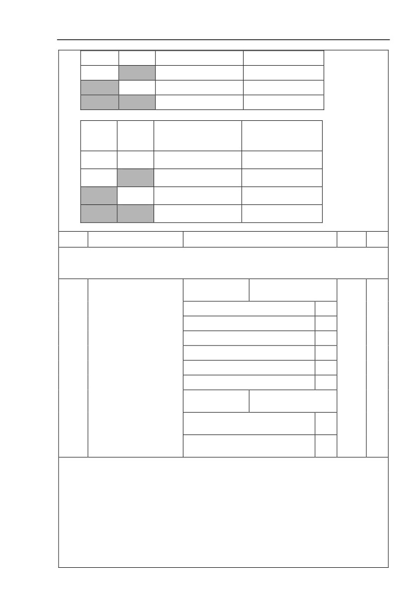
Schedule 2 Acceleration / deceleration terminal selection description:
Corresponding
Terminal2
Terminal1
Acc./dec. selection
parameter
62
Section V. Parameter Function Table
OFF
OFF
Acc./dec. time 1
P0.17、P0.18
OFF
ON
Acc./dec. time 2
P8.03、P8.04
ON
OFF
Acc./dec. time 3
P8.05、P8.06
ON
ON
Acc./dec. time 4
P8.07、P8.08
Schedule 3 Motor terminal selection description:
Corresponding
Terminal2
Terminal1
Acc./dec. selection
parameter
OFF
OFF
Motor 1
P1、P2 group
OFF
ON
Motor 2
A2 group
ON
OFF
Motor 3
A3 group
ON
ON
Motor 4
A4 group
P4.10
DI filter time
0.000s~1.000s
0.010s
☆
If the digital input terminal malfunction because it is vulnerable to interference , users could increase
the parameter value to enhance the interference immunity. However, this operation may cause reduced
sensitivity of the DI terminal.
Terminal input command
1bit
mode
Two-line mode 1
0
Two-line mode 2
1
Three-line mode1
2
Three-line mode2
3
P4.11
Terminal command mode
Two-line mode 3
4
0
★
Three-line mode3
5
Terminal input priority
10bit
mode
Point
move priorrun command
0
FWD,REV
run command FWD,REV priorPoint
1
move
0 bit:
This parameter defines 6 different modes of controlling the forward and reverse rotations of the inverter via
the external terminal.
NOTE::In order to explain,The following arbitrary selection DI1~DI10 multifunctional input terminal
DI1、DI2、DI3 three terminals as external terminals,That is, by setting the value ofP4.00~P4.02 to select
DI1、DI2、DI3 three terminal functions。Detailed function definition is P4.00~P4.09 setting range
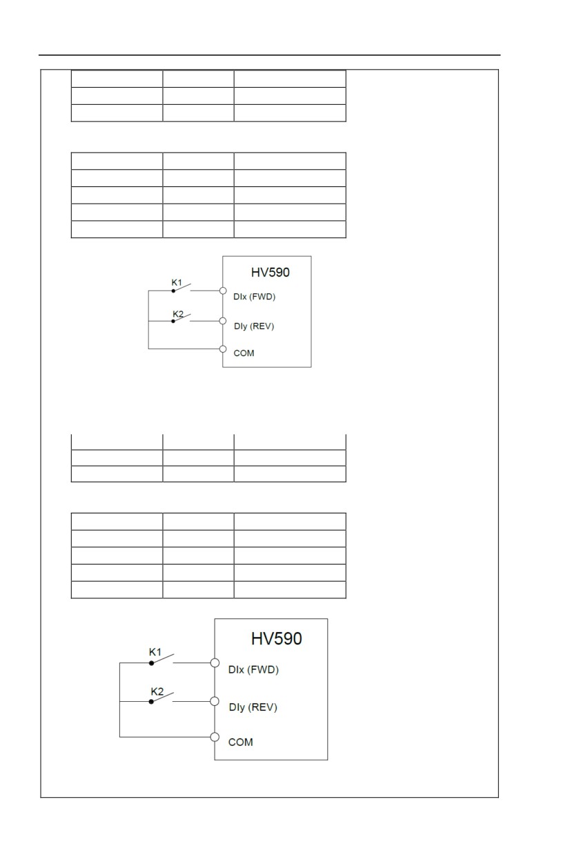
0:Two-line mode 1:
This mode is the most commanly used forward/reverse rotation control mode. The forward/reverse
rotation of the motor is decidedby the Di1, DI2 terminal commands. The descriptions on the terminal running
command are as shown as below:
63
Section V. Parameter Function Table
Terminal
Set value
Description
DI1
1
Forward(FWD)
DI2
2
Reverse(REV)
Among them ,DI1、DI2 are DI1~DI10 muti-fuction input terminal, level valid.
0 invalid,1 valid
K1
K2
Command
0
0
Stop
0
1
Reverse(REV)
1
0
Forward(FWD)
1
1
Stop
Fig. 5-6 Two-line control mode 1
1: Two-line mode 2:
In this operation mode,DI1 terminal function is to enable operation,while DI2 terminal function is to
determine running direction. The descriptions on the terminal running command are as shown as below:
Terminal
Set value
Description
DI1
1
Forward(FWD)
DI2
2
Reverse(REV)
Among them ,DI1、DI2 are DI1~DI10 multi-fuction input terminal, level valid
0 invalid,1 valid
K1
K2
Command
0
0
Stop
0
1
Stop
1
0
Forward(FWD)
1
1
Reverse(REV)
Fig. 5-7 Two-line control mode 2
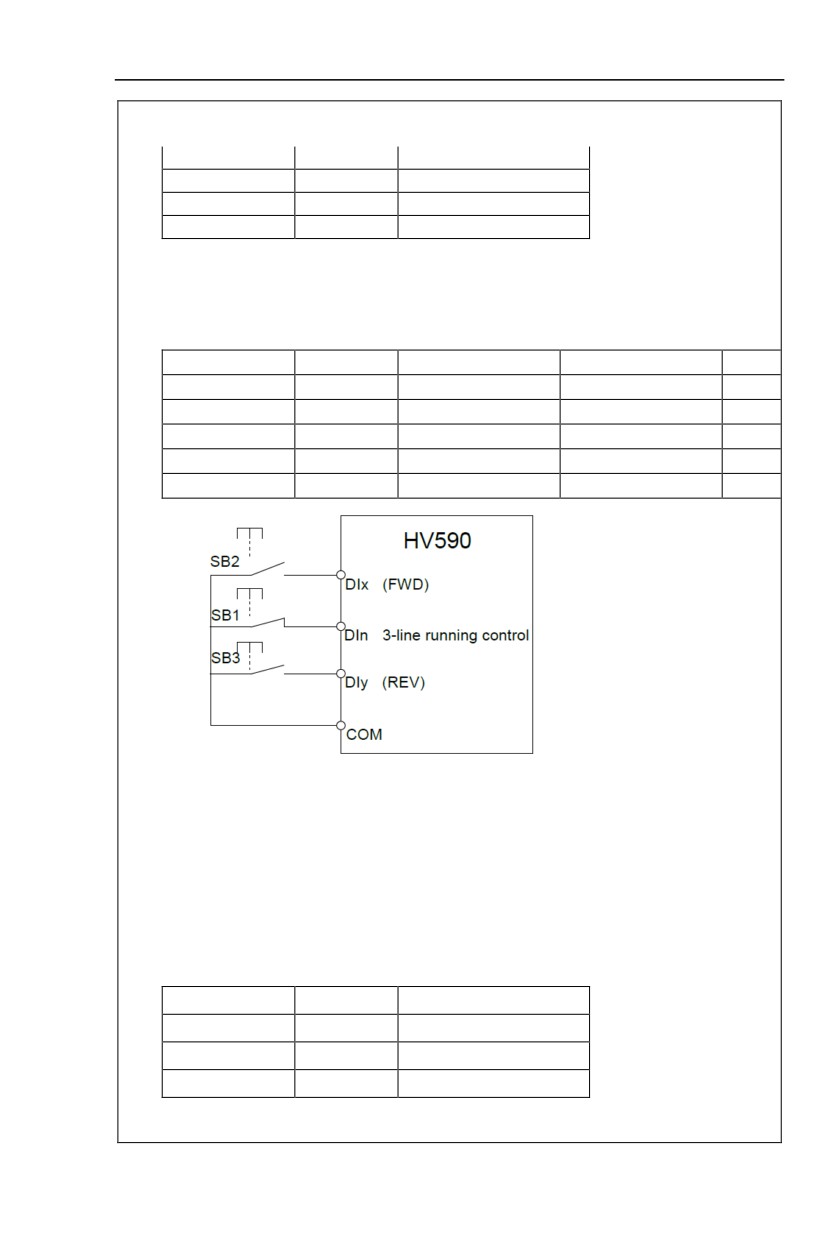
2:Three-line mode1
Section V. Parameter Function Table
In this operation mode, DI3terminal is the enable terminal, running direction controlled by
DI1terminal 、DI2terminal. The descriptions on the terminal running command are as shown as below:
Terminal
Set value
Description
DI1
1
Forward(FWD)
DI2
2
Reverse(REV)
DI3
3
Three-line running control
When in the need of running, users should first connect DI3 terminal. Forward and reverse running is
realized through the rising edge of Di1 or DI2.
When in the need of stop, user should disconnect DI3 terminal to meet the need. Among them, DI1、
DI2、DI3 are multi-function input terminal of DI1~DI10. DI1,DI2 are of pulse valid, while DI3 level valid.
0 invalid. 1 valid. X arbitrarily
SB1
SB2
SB3
Command
0
X
X
Stop
1
1
0
Forward(FWD)
1
0
1
Reverse(REV)
1
1
0->1
Reverse(REV)
1
0->1
1
Forward(FWD)
Fig. 5-8 Three-line control mode 1
Among them:
SB1:Stop button
SB2:Forward rotation button
SB3:Reverse rotation button
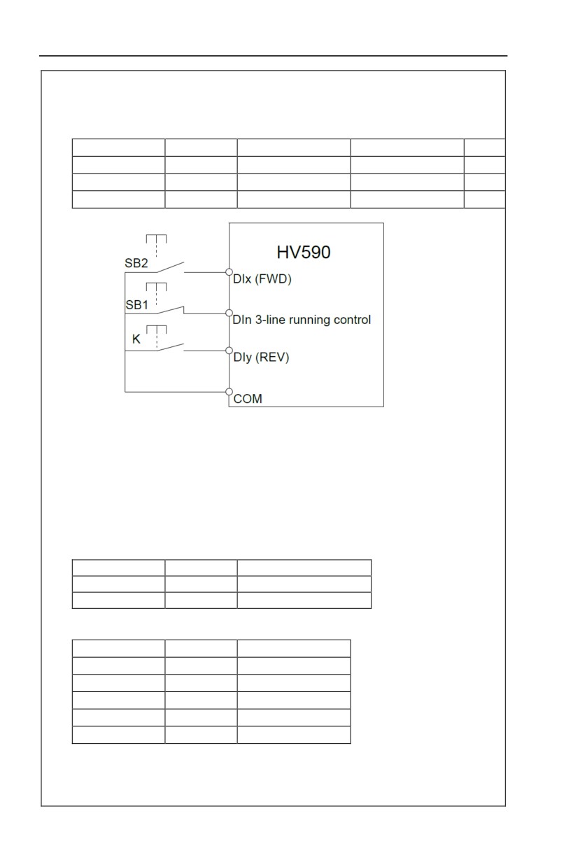
3:Three-line mode2
In this operation mode, DI3 terminal is the enable terminal, Direction by the state of the DI2 to decide,while
DI1 terminal function is to determine running direction. The descriptions on the terminal running command
are as shown as below:
Terminal
Set value
Description
DI1
1
Forward(FWD)
DI2
2
Reverse(REV)
DI3
3
Three-line running control
When in the need of running, users should first connect DI3 terminal. DI1 pulse rising edge gives
running command signal, while DI2 status gives running direction signal.
65
Section V. Parameter Function Table
When in the need of stop, user should disconnect DIn terminal to meet the need. Among them, DI1, DI2,
DI3 are multi-function input terminals of DI1~DI10. DI1 is of pulse valid, while DI2, DI3is of level valid.
0 invalid. 1 valid. X arbitrarily
SB1
SB2
K
Command
0
X
X
Stop
1
1
0
Forward(FWD)
1
1
1
Reverse(REV)
Fig. 5-9 Three-line control mode 2
Among them :
SB1:Stop button
SB2:Running button
4:Two-line mode3
this operation mode is Priority control two-line mode.The forward/reverse rotation of the motor is
decidedby the Di1, DI2 terminal commands. The descriptions on the terminal running command are as
shown as below:
Terminal
Set value
Description
DI1
1
Forward(FWD)
DI2
2
Reverse(REV)
Among them ,DI1、DI2 are DI1~DI10 multi-fuction input terminal, level valid
0 invalid,1valid
K1
K2
Command
0
0
Stop
0
1
Reverse(REV)
1
0
Forward(FWD)
1
0->1
Forward(FWD)
0->1
1
Reverse(REV)
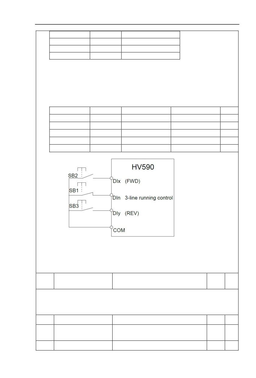
5:Three-line mode3
In this operation mode, DI3 terminal is the enable terminal, running direction controlled by
DI1terminal 、DI2terminal. The descriptions on the terminal running command are as shown as below:
66
Section V. Parameter Function Table
Terminal
Set value
Description
DI1
1
Forward(FWD)
DI2
2
Reverse(REV)
DI3
3
Three-line running control
When in the need of running, users should first connect DI3 terminal. Forward and reverse running is
realized through the rising edge of Di1 or DI2
Direction as first control priority control,when DI1 is valid,DI2 pulse rising edge is invalid,when DI2 is
valid,DI1 pulse rising edge is invalid,When in the need of stop, user should disconnect DI3 terminal to
meet the need. Among them, DI1、DI2、DIn are multi-function input terminal of DI1~DI10. DI1,DI2 are of
pulse valid, while DI3 level valid.
0 invalid. 1 valid. X arbitrarily
SB1
SB2
SB3
Command
0
X
X
Stop
1
1
0
Forward(FWD)
1
0
1
Reverse(REV)
1
1
0->1
Forward(FWD)
1
0->1
1
Reverse(REV)
Fig. 5-8 Three-line control mode 1
Among them:
SB1:Stop button
SB2:Forward rotation button
SB3:Reverse rotation button
Terminal UP/DOWN variation
P4.12
0.01Hz/s~65.535Hz/s
1.00Hz/s
☆
rate
It is used to set the frequency variation rate (frequency variation per second) when adjusting the set
frequency with terminals UP/DOWN.
When P0.22 (frequency decimal point) is set to 2, range of P4.12 value is 0.001Hz/s~65.535Hz/s.
When P0.22 (frequency decimal point) is set to 1, range of P4.12 value is 0.01Hz/s~655.35Hz/ s.
P4.13
AI curve 1 minimum input
0.00V~P4.15
0.00V
☆
AI curve 1 minimum input
P4.14
-100.00%~100.0%
0.0%
☆
corresponding setup
P4.15
AI curve 1 maximum input
P4.13~10.00V
10.00V
☆
67
Section V. Parameter Function Table
AI curve 1 maximum input
P4.16
-100.00%~100.0%
100.0%
☆
corresponding setup
P4.17
AI1 filter time
0.00s~10.00s
0.10s
☆
Corresponding setting
(frequency,torque)
100%
A1
0V(0mA)
10V(20mA)
Corresponding setting
(frequency,torque)
100%
A1
0V(0mA)
10V(20mA)
-100%
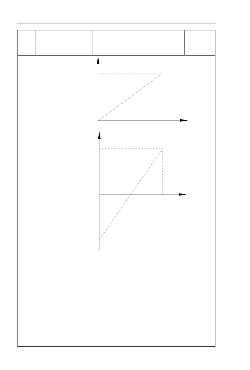
Fig. 5-10 Relationship between analog input and setup value
The parameters mentioned above define the relationship between analog input voltage and the analog
input setup value.
When analog input voltage exceeds the setup “maximum input” limit, analog voltage is calculated as
“maximum input” .Similarly, when analog input is smaller than the setup “minimum input”,analog voltage is
calculated as minimum input or 0.0% according to the setting of P4.34.
AI used as current input terminal :1mA current equals to 0.5V voltage.
AI input filtering time is used to set AI1 software filtering time.When field anlog quantity is vulnerable,
please increase the filtering time so that anlog quantity tends to be stable. But excessive filtering time will
lead to slow response time to anlog detection. User should balance it according to practical application
cases.
In various application cases, the nominal value corresponding to 100% of analog reference will be
different. Refer to specific application description for the specific value.
68
Section V. Parameter Function Table
Figure 5.10 shows typical setup cases.
P4.18
AI curve 2 minimum input
0.00V~P4.20
0.00V
☆
AI curve 2 minimum input
P4.19
-100.00%~100.0%
0.0%
☆
corresponding setup
P4.20
AI curve 2 maximum input
P4.18~10.00V
10.00V
☆
AI curve 2 maximum input
P4.21
-100.00%~100.0%
100.0%
☆
corresponding setup
P4.22
AI2 filter time
0.00s~10.00s
0.10s
☆
For function and usage of curve 2, please refer to description of curve 1.
P4.23
AI curve 3 minimum input
-10.00V~P4.25
-10V
☆
AI curve 3 minimum input
P4.24
-100.00%~100.0%
0.0%
☆
corresponding setup
P4.25
AI curve3 maximum input
P4.23~10.00V
8.60V
☆
AI curve 3 maximum input
P4.26
-100.00%~100.0%
100.0%
☆
corresponding setup
P4.27
AI3filter time
0.00s~10.00s
0.10s
☆
For function and usage of curve 3, please refer to description of curve 1.
P4.28
PULSE minimum input
0.00kHz~P4.30
0.00kHz
☆
PULSE minimum input
P4.29
-100.00%~100.0%
0.0%
☆
corresponding setup
P4.30
PULSE maximum input
P4.28~50.00kHz
50.00kHz
☆
PULSE maximum input
P4.31
-100.00%~100.0%
100.0%
☆
corresponding setup
P4.32
PULSE filter time
0.00s~10.00s
0.10s
☆
This group of parameters are used to set relationship between DI5 pulse frequency and it’s
corresponding settings.
Pulse frequency can be only input to the inverter through DI5 channel. This function group’s
applications are similar to curve 1,please refer to the description of curve 1.
1bit
AI1 curve selection
Curve1(2 points,see P4.13~P4.16)
1
Curve2(2 points,see P4.18~P4.21)
2
Curve3(2 points,see P4.23~P4.26)
3
P4.33
AI curve selection
321
☆
Curve4(4 points,see A6.00~A6.07)
4
Curve5(4 points,see A6.08~A6.15)
5
10bit
AI2 curve selection
Curve1(2 points,see P4.13~P4.16)
1
69
Section V. Parameter Function Table
Curve2(2 points,see P4.18~P4.21)
2
Curve3(2 points,see P4.23~P4.26)
3
Curve4(4 points,see A6.00~A6.07)
4
Curve5(4 points,see A6.00~A6.07)
5
100bit
AI3 curve selection
Curve1(2 points,see P4.13~P4.16)
1
Curve2(2 points,see P4.18~P4.21)
2
Curve3(2 points,see P4.23~P4.26)
3
Curve4(4 points,see A6.00~A6.07)
4
Curve5(4 points,see A6.00~A6.07)
5
The 1bit, 10bit, 100bit of the function code are used to choose the set curve of analog input AI1、
AI2、AI3 respectively.
3 analog input can choose any curve of the 5 types.
Curve1, curve 2, curve 3 are 2 points curve that set through P4 group function codes, while curve 4,
curve 5 are 4 points curve that set through A8 group function codes.
HV590 standard unit offers 3-channel analog input terminals. Multi-function I/O expansion card is
needed in the use of AI3x.
AI1 below minimum input setup
1bit
selection
Minimum input setup
0
0.0%
1
10bit
AI2 below minimum input setup selection
AI below minimum input
P4.34
Minimum input setup
0
000
☆
setup selection
0.0%
1
100bit
AI3 below minimum input set selection
Minimum input setup
0
0.0%
1
This function code is used to dertermine analog quantity corresponding setup when analog input
voltage below the setup of minimum input.
The 1bit, 10bit, 100bit of the function code are corresponding to the analog input AI1、AI2、AI3
respectively. If the bit is set to 0 and AI is below the minimum setup , the analog input setup is the curve
“minimum input corresponding setup”(P4.14、P4.19、P4.24) . If the bit is set to 0 and AI is below the
minimum setup , the analog quantity corresponding setup is 0.0%.
P4.35
DI1 delay time
0.0s~3600.0s
0.0s
★
P4.36
DI2 delay time
0.0s~3600.0s
0.0s
★
P4.37
DI3 delay time
0.0s~3600.0s
0.0s
★
Only DI1, DI2, DI3 are able to set equipment delay time.
70
Section V. Parameter Function Table
They are used to set delay time to inverter DI terminal state change.
1bit
DI1 terminal valid state setup
High level valid
0
Low level valid
1
10bit
DI2 terminal valid state setup
High level valid
0
Low level valid
1
100bit
DI3 terminal valid state setup
DI terminal effective mode
High level valid
0
P4.38
00000
★
selection 1
Low level valid
1
1000
DI4 terminal valid state setup
bit
High level valid
0
Low level valid
1
1000
DI5 terminal valid state setup
0bit
High level valid
0
Low level valid
1
1bit
DI6 terminal valid state setup
High level valid
0
Low level valid
1
10bit
DI7 terminal valid state setup
High level valid
0
Low level valid
1
100bit
DI8 terminal valid state setup
DI terminal effective mode
High level valid
0
P4.39
00000
★
selection 2
Low level valid
1
1000
DI9 terminal valid state setup
bit
High level valid
0
Low level valid
1
1000
DI10 terminal valid state setup
0bit
High level valid
0
Low level valid
1
71
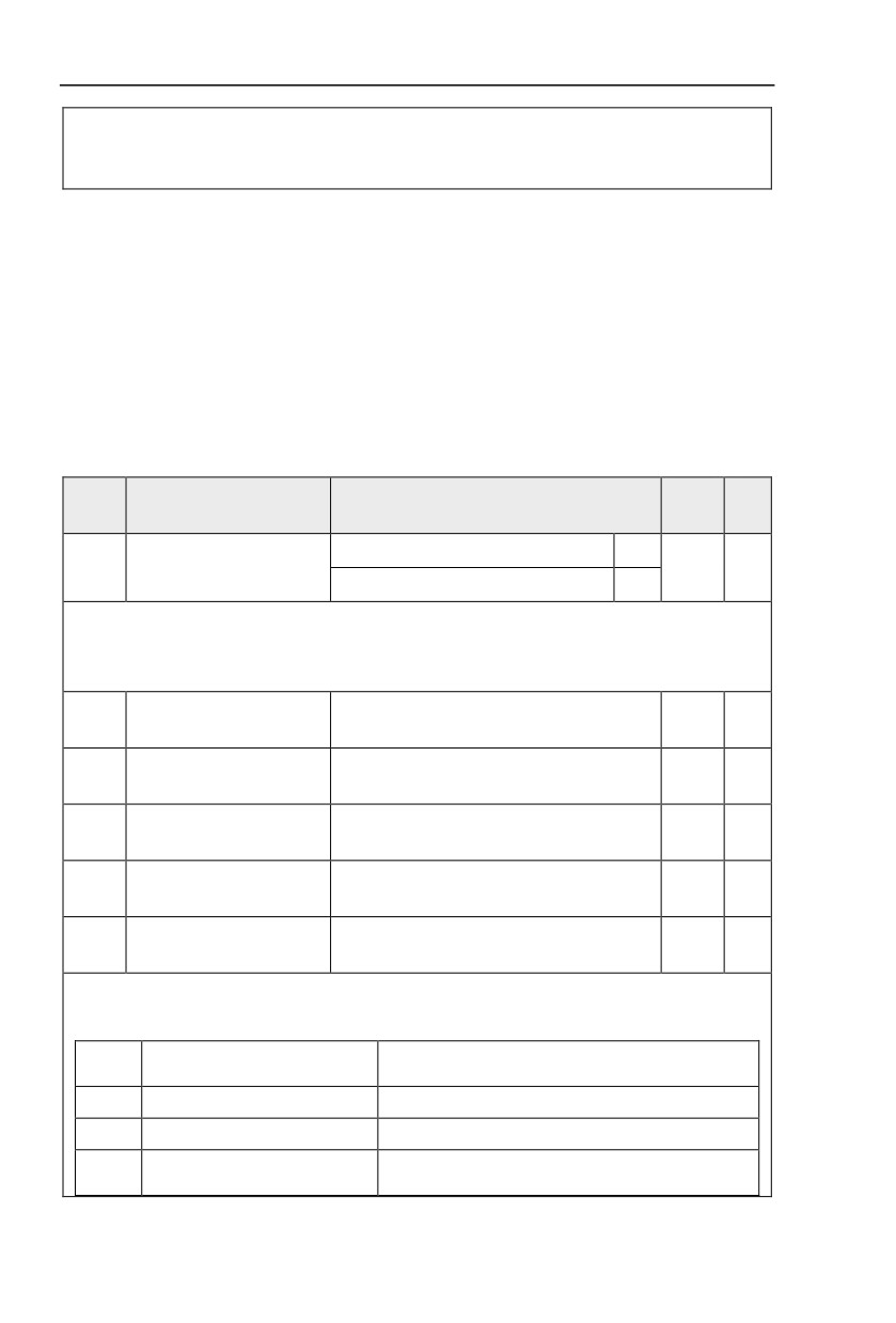
Section V. Parameter Function Table
It is used to set digital input terminal effective mode.
High level valid:Connection between COM and corresponding DI is valid,disconnection invalid.
Low level valid:Connection between COM and corresponding DI is invalid,disconnection valid.
5.7 Output terminal:P5.00-P5.22
HV590 series inverter provides two multifunctional analog terminal output selections,two
multifunctional relay output terminal, oneDO terminal (can be used as high speed pulse output
terminal as well as open collector switching output). If the above output terminals can not meet
the field application, users should choose optional multi-function input/output expansion card.
Output terminals of multi-fuction input/output expansion card contain 1 multi-function analog
output terminal(DO2), 1 multi-function relay output terminal (relay 2) , 1 multi-function digital
output terminal(DO2).
Description/
FactoryChange
Code
Setting Range
Keyboard Display
Setting
Limite
Pulse output(Y1P)
0
Y terminal output mode
P5.00
0
☆
selection
Switch output(Y1R)
1
Y1 is programmable multiplex terminal, which can be used as high speed pulse output terminal (Y1P)
or open collector switching output terminal (Y1R).
When P5.00 is set to 0, maximum output frequency can reach 10kHz , please refer to P5.06 for related
description.
Y1Rselection (open
P5.01
0-40
0
☆
collector output terminal)
Relay output selection
P5.02
0-40
2
☆
(TA1.TB1.TC1)
Expansion card relay output
P5.03
0-40
2
☆
selection(TA2.TB2.TC2)
DO1 output selection(open
P5.04
0-40
1
☆
collector output terminal)
Expansion card DO2 output
P5.05
0-40
1
☆
selection
The above
5 function codes are used to select
5 digital output function. TA1.TB1.TC1 and
TA2.TB2.TC2 are control board and expansion card relay respectively.
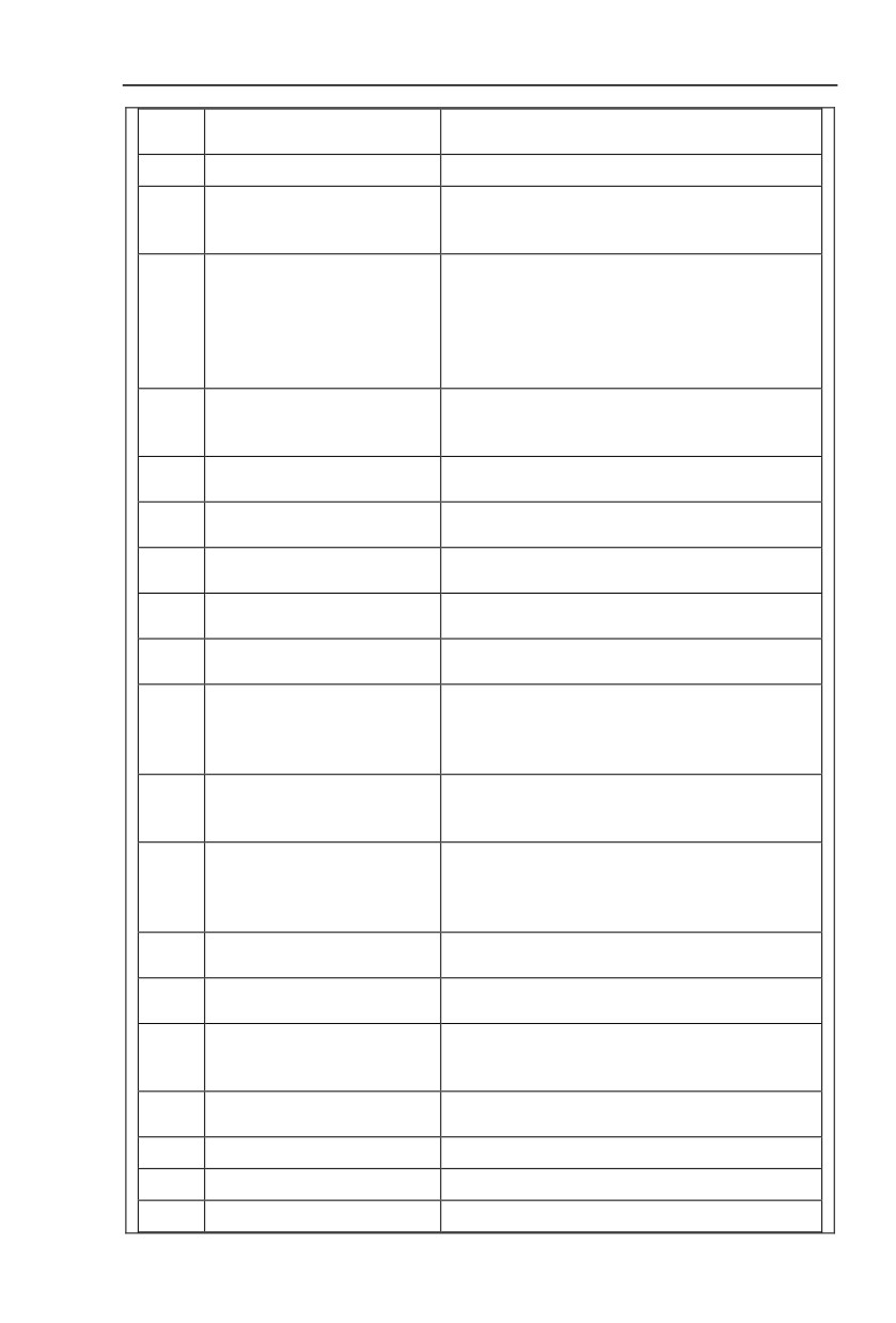
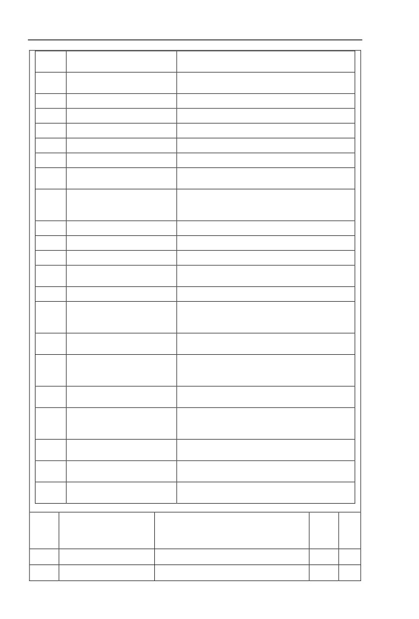
Function selections are as follows:
Set
Function
Description
value
0
No output
The output terminals have no function
1
Inverter in operation
When the inverter is running, ON signal is output.
When inverter fault happens and stops due to the fault ,
2
Output fault(Stop fault)
ON signal is output
72
Section V. Parameter Function Table
Frequency level detection FDT1
3
Refer to P8.19 and P8.20 function codes for details
output
4
Frequency arrival
Refer to P8.21 function codes for details
When inverter is in running status and output 0Hz , ON
Null speed operation(stop without
5
signal is output.
output)
When inverter is in stop status, OFF signal is output.
Judgment will be made according to the prealarm
parameter value before the motor electronic thermal
protection is enabled. If it exceeds the pre-alarm
6
Motor overload pre-alarm
parameter value, ON signal will be output. Refer to
P9.00 to P9.02 function codes for the descriptions of
motor overload.
When it is found that the inverter is overloaded, ON
7
Inverter overload pre-alarm
signal will be output before the overload protection
occurs.
When the counting value reaches the value of PB.08, it
8
Setup counting value arrived
outputs ON signal.
When the counting value reaches the value of PB.09, it
9
Designated counting value arrived
outputs ON signal.Refers to PB group for details.
When the actual length exceeds the setup value in
10
Length arrived
PB.05, it outputs ON signal.
When the simple PLC running finishes one circulation, it
11
PLC circulation end
outputs a pulse signal with width of 250ms.
When the accumulated running time of the inverter
12
Total running time arrived
exceeds the setup time (P8.17), it outputs ON signal.
When set frequency exceeds upper limit frequency or
lower limit frequency,and inverter output frequency
13
Frequency limit
exceeds upper limit frequency or lower limit frequency,
it outputs ON signal.
In speed control mode, if output torque reaches the
14
Torque limit
torque limit, inverter will be in stall protection status and
output ON signal.
When the inverter has no fault and the bus voltage
works normally and the inverter is ready for running, it
15
RUN ready
outputs ON signal. Upon normal startup, it closes the
output.
When the voltage value of analog input AI1 is bigger
16
AI1>AI2
than that of analog input AI2, it output ON signal.
When the running frequency of the inverter reaches the
17
Frequency upper limit arrived
frequency upper limit, it outputs ON signal.
When the running frequency of the inverter reaches the
Frequency lower limit arrived
18
frequency lower limit, it outputs ON signal.And output
(stop without output)
OFF signal in stop status.
When inverter is in undervoltage status, it outpus ON
19
Undervoltage state output
signal.
20
Communication setup
Please refer to communication protocol.
21
Reserved
Reserved
22
Reserved
Reserved
73
Section V. Parameter Function Table
Null speed operation 2(Stop with
When inverter output 0Hz , ON signal is output.
23
output)
When inverter is in stop status, ON signal is output.
When accumulated power-on time(P7.13) exceeds
24
Total power-on time arrival
P8.16 set value, it outputs ON signal.
25
Inspection level of FDT2 frequency
Please refer to function code P8.28、P8.29 for details.
26
Frequency 1 arrival output
Please refer to function code P8.30、P8.31 for details.
27
Frequency 2 arrival output
Please refer to function code P8.32、P8.33 for details.
28
Current 1 arrival output
Please refer to function code P8.38、P8.39 for details.
29
Current 2 arrival output
Please refer to function code P8.40、P8.41 for details.
When inverter running time reaches the set timming
30
Timing arrival output
(P8.42 valid), it outputs ON signal.
When analog input value AI1 is bigger than P8.46 (AI1
31
AI1excessive input
input protection upper limit) or smaller than P8.45(AI1
input protection lower limit), it outpus ON signal.
32
Load off
Inverter in load off status, it outpus ON signal.
33
Reverse running
Inverter in reverse running mode, it outputs ON signal.
34
Zero current state
Please refer to function code P8.28、P8.29 for details.
When module radiator temperature(P7.07) reaches the
35
Module temperature arrival
set value of P8.47, it outputs ON signal.
36
Software excessive current
Please refer to function code P8.36、P8.37 for details.
When running frequency reaches frequency lower limit,
Frequency lower limit arrival(stop
37
it outputs ON signal.When in stop status ,it outputs ON
with output)
signal too.
When inverter fault with processing mode of continue
38
Alarm output
running, it outputs alarm signal.
When motor temperature reaches set value of P9.58 , it
39
Motor over temperature alarm
outputs ON signal.(temperature can be viewed through
U0.34)
When the running time exceeds the set value of P8.53 ,
40
The running time arrival
it outputs ON signal.
When inverter fault with processing mode of continue
41
Alarm output
running(uninclude under voltage fault), it outputs alarm
signal.
running command status direct output
( run
42
running command status output
command)
Forward running command
Forward running command status direct output
43
status output
(forward run command)
Reverse running command
Reverse running command status direct output
44
status output
(Reverse run command)
Y1P output function
P5.06
selection(pulse output
0-16
0
☆
terminal)
P5.07
AO1 output function selection
0-16
0
☆
P5.08
AO2 output function selection
0-16
1
☆
74
Section V. Parameter Function Table
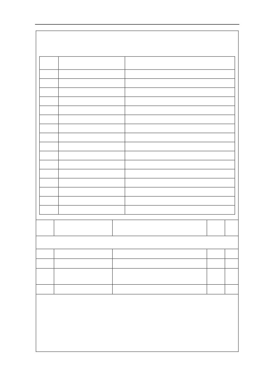
Y1P terminal output pulse frequency range:0.01kHz~P5.09(Y1P maximum frequency output), P5.09
could vary from 0.01kHz to 100.00kHz.
AO1, AO2 output ranges from 0V to 10V, or 0mA to 20mA.
The corresponding value range is shown in the table below:
Setup
Function
Range
value
0
Running frequency
0~maximumoutputfrequency
1
Setupfrequency
0~maximumoutputfrequency
2
Outputcurrent
0~200%ofthe rated current oftheinverter
3
Outputtorque
0~200%ofthe rated torque oftheinverter
4
Outputpower
0~200% ofthe rated powerofthe inverter
5
Output voltage
0~120% of the rated voltage of the inverter
6
PULSEpulse input
0.01kHz~100.00kHz
7
AI1
0V~10V
8
AI2
0V~10V(Or 0~20mA)
9
AI3
0V~10V
10
Length
0~Maximum length
11
Countingvalue
0~Maximum counting value
12
Communication setup
0.0%~100.0%
13
Motor revolving speed
0~maximum output frequency corresponding speed
14
Output current
0.0A~1000.0A
15
Output voltage
0.0V~1000.0V
Y1P maximum output
P5.09
0.01kHz~100.00kHz
50.00kHz
☆
frequency
When the multifunctional terminal output function selects Y1P pulse output, it can set the maximum
frequency value of output pulse.
P5.10
AO1 zero offset
-100.0%~+100.0%
0.0%
☆
P5.11
AO1 gain
-10.00~+10.00
1.00
☆
Expansion card AO2zero
P5.12
-100.0%~+100.0%
0.00%
☆
offset
P5.13
Expansion card AO2 gain
-10.00~+10.00
1.00
☆
Function codes above are generally used to modify the zero drift of the analog output and also be
used to define required AO output curves.
If b represents zero offset, k represents gain, Y represents actual output, and X represents standard
output, the actual output is calculated as follows: Y=kX+b
AO1, AO2 zero offset coefficient 100% corresponds to 10V (20mA).
For example, if the analog output is the running frequency, and it is expected to output 8V (16mA)
when the frequency is 0, and output 3V (6mA) at the maximum frequency, the standard output 0V to 10V
shall be modified to 8V to 3V output. As per the above formula, AO zero offset coefficient shall be set to
“80%”, while A0 gain shall be set to “-0.50”.
75
Section V. Parameter Function Table
P5.17
Y1R output delay time
0.0s~3600.0s
0.0s
☆
P5.18
RELAY1 output delay time
0.0s~3600.0s
0.0s
☆
P5.19
RELAY2 output delay time
0.0s~3600.0s
0.0s
☆
P5.20
DO1 output delay time
0.0s~3600.0s
0.0s
☆
P5.21
DO2 output delay time
0.0s~3600.0s
0.0s
☆
Set output terminal Y1R, relay 1, relay 2, DO1 and DO2 delay time that begins from status changing to
real output changing.
1bit
Y1R valid state selection
Positive logic
0
Negative logic
1
10bit
RELAY1 terminal valid state setup
Positive logic
0
Negative logic
1
100bit
RELAY2 terminal valid state setup
Positive logic
0
DO output terminal valid
P5.22
00000
☆
state selection
Negative logic
1
1000
DO1 terminal valid state setup
bit
Positive logic
0
Negative logic
1
10000
DO2 terminal valid state setup
bit
Positive logic
0
Negative logic
1
Define output terminal Y1R、Relay 1、Relay 2、DO1 andDO2 output logic.
0: Positive logic
Digital output terminals and the corresponding public end connected as effective state, disconnect for
invalid state.
1:Negative logic
Digital output terminals and the corresponding public end connected as invalid state, disconnect for
effective state.
5.8 Start/stop control:P6.00-P6.15
Description/
FactoryChange
Code
Setting Range
Keyboard Display
Setting
Limite
P6.00
Start mode
Direct startup
0
0
☆
76
Section V. Parameter Function Table
Revolving speed tracking startup
1
Pre-excitation startup
2
(AC asynchronous motor)
0: Direct startup:
When the DC brake time is zero, it starts at the startup frequency.
When the DC brake time is non-zero value, it can perform DC brake before start. It is suitable for the
applications where small inertia may cause reverse rotation at the time of startup.
1:Revolving speed tracking startup:
The inverter firstly judges the revolving speed and direction of the motor and then starts at the
frequency corresponding to the tracked rotation velocity of the motor, and performs smooth startup of the
motor in rotation without impact.It is suitable for the applications where large inertia is restarted due to
transient power shutdown.In order to ensure the performance of the rotation velocity tracking startup, motor
parameters (Group P1) should be set correctly.
2:Asynchronous pre-excitation startup
It is only valid for asynchronous motor , and is used to establish magnetic field before motor operation.
For pre-excitation current, pre-excitation time please refer to function code P6.05 and P6.06.
If pre-excitation time is set to 0, the pre-excitation process will be cancelled ,and start with start
frequency. If pre-excitation time is not set to 0, inverter first pre-excitation then starup. In this way, motor
dynamic response performance is promoted.
Start from stop frequency
0
Revolving speed tracking
P6.01
Start from zero speed
1
0
★
mode
Start from maximum frequency
2
In order to complete the rotation speed tracking process in the shortest period, it can select the mode
of inverter tracking the rotation velocity of motor:
0: Track downward from the frequency at the time of stop, which is generally selected at first.
1: Track upward from zero frequency, which is used when the inverter is restarted upon long period of
power shutdown.
2: Track downward from the maximum frequency, which is generally used for power generating load.
Revolving speed tracking
P6.02
1~100
20
☆
speed
In the mode of revolving speed tracking startup, it is used to select the speed of rotation tracking. The
higher the parameter value is, the faster the tracking velocity is, but too higher value may cause unreliable
tracking.
P6.03
Start frequency
0.00Hz~10.00Hz
0.00Hz
☆
P6.04
Start frequency holding time
0.0s~100.0s
0.0s
★
To ensure the torque at the time of startup, proper startup frequency shall be set. In addition, in order
to set up magnetic flux when waiting for the startup of the motor, the startup frequency shall remain for a
certain period of time before accelerating to the setup frequency.
Start frequency P6.03 is not affected by the lower frequency limit.If the frequency reference value
(frequency source) is lower than the startup frequency, the inverter cannot start and will be in standby
status.
In positive&negative switching process, startup frequency retention time Yes not work.Startup
frequency retention time is not included in the acceleration time,but included in the simple PLC running
time.
Example 1:
P0.03=0 means the frequency source is digital reference.
P0.08=2.00Hz means the digital setup frequency is 2.00Hz.
77
Section V. Parameter Function Table
P6.03=5.00Hz means the startup frequency is 5.00Hz.
P6.04=2.0s means that the startup frequency retention time is 2.0s.
In this case, the inverter will be in the standby status and its output frequency is 0Hz.
Example 2:
P0.03=0 means the frequency source is digital reference.
P0.08=10.00Hz means the digital setup frequency is 10.00Hz.
P6.03=5.00Hz means the startup frequency is 5.00Hz.
P6.04=2.0s means that the startup frequency retention time is 2.0s.
In this case, the inverter accelerates to 5.00 Hz and remains for 2 seconds, and then accelerates to
the setup frequency 10Hz.
Start dc braking current
P6.05
0%~100%
0%
★
/pre-excitation current
Start dc braking time /pre-
P6.06
0.0s~100.0s
0.0s
★
excitation time
Pre-excitation is used to establish asynchronous motor magnetic field before startup, which would
improve response speed.
Start dc current braking is only valid when it is direct startup. Inverter first carries out dc braking
according to the setup of start dc current braking , and then carries out operation after start dc braking
time.
If dc braking time is set to 0, inverter directly start without dc braking. The bigger the dc braking current
is , the greater the braking force is.
If start mode is asynchrounous motor pre-excitation start, inverter first establish magnetic field through
pre-excitation current setup, then start to run after pre-excitation time. If set pre-excitation time to 0,
inverter would directly start without pre-excitation process./
Start dc braking current/pre-excitation current is the relative percentage of rated current.
Straight acc. /dec.
0
Acceleration/ deceleration
P6.07
0
★
mode
S curve acc. /dec. mode A
1
It is used to select the frequency change mode during the inverter start and stop process.
0: Straight acceleration/ deceleration
The output frequency increases or decreases along the straight line. HV590 series inverter provides 4
types of acceleration/deceleration time.It can select acceleration/ deceleration time via the multifunctional
digital input terminals.
1:S-curve acceleration/ deceleration mode A
The output frequency increases or decreases along the straight line. S curve is generally used in the
applications where start and stop processes are relatively gentle, such as elevator and conveyor belt.The
acceleration/ deceleration time is consistent with the straight acceleration/ deceleration time.Function
codes of P6.08 and P6.09 can be respectively definedthe time proportion of starting-segment and finishing-
segment for S-curve acceleration/ deceleration.
Initial-segment time
P6.08
0.0%~(100.0%.P6.09)
30.0%
★
proportion of S-curve
Finishing-segment time
P6.09
0.0%~(100.0%.P6.08)
30.0%
★
proportion of S-curve
Function code of P6.08 and P6.09 can be respectively defined the time proportion between the S-
curve initial-segment and finishing-segment for S-curve acceleration/ deceleration A. They are required to
meet the standard of P6.08+P6.09≤100.0%.
t1 in the Fig.5-11 is the parameters defined by P6.08, in this period of time which the changing slope
of output frequency is becoming larger and larger. t2 is defined by parameter P6.09, in this period of time
78