HV590 Series Frequency Inverter. User Manual (Version: 3.1.14) - page 1
HV590 Series Frequency Inverter
User Manual
HNC Electric Limited
Foreword
Thank you for using the HV590 series of high-performance vector inverter.
New HV590 series is a general current vector control inverter integrated with the
performance and features in a high degree.
HV590 with industry-leading drive performance and functionality control, using unique
current vector control algorithm can efficiently drive induction motor to achieve high
accuracy, high torque and high-performance control.
Customer success, Market Serivce!HV590 in terms of performance and control are
worthy of trust!
This guide explains how to properly use HV590 series inverter. Before using
(installation, operation, maintenance, inspection, etc.), be sure to carefully read the
instructions. Understanding of product safety precautions before using this product.
Definition of security
In this manual, safety issues the following two categories:
Warning: Due to the dangers posed against the required operation, may result
in serious injury and even death;
Causion: Due to the dangers posed against the required operation, may lead
to moderate harm or minor injuries, and damage to the equipment;
Installation, commissioning and maintenance of the system, please carefully read this
chapter (safety precautions), follow the required safety precautions to operate. HNC is not
responsible in case of any injuries and losses caused as a result of improper operations.
Safety precautions
Before Installation
Warning
Do not install inverter finding the control system with water in, or inverter with missing parts
or damaged parts.
Please do not install inverter when the packing list is not consistent with the physical name.
Warning
Carefully handled when loading, otherwise it may damage the inverter.
Please don’t use the damaged driver or missing parts inverter, there may be risk of injury.
Do not touch components of the control system, otherwise it will cause danger of static
electricity.
During Installation
Warning
Mount the inverter on incombustible surface like metal, and keep away from flammable
substances. Otherwise it may cause fire.
Do not twist the mounting bolt of the equipment, especially the screw bolt marked in RED.
Prohibit the use in the dangerous environment where inflammable or combustible or
explosive gas, liquid or solid exists. Or it may cause electric shock or fire.
Caution
Do not drop the conducting wire stub or screw into the inverter. Otherwise ,it may cause
damage to the inverter.
Please install the inverter at the place of less direct sunlight and vibration.
Please mind the location of its installation when more than two inverters are installed in one
cabinet, so that radiation effect is promised.
During Wiring
Warning
Operation shall be performed by the professional engineering technician. Otherwise there
will be unexpected danger.
There shall be circuit breaker between the inverter and power supply. Otherwise, there may
be fire.
Make sure the power is disconnected prior to the connection. Otherwise there will be danger
of electric shock.
The earth terminal shall be earthed reliably. Otherwise there may be danger of electric shock.
Warning
Please don't put the power line and the signal line from the same pipeline,when operating
wiring, please make power line and signal line apart above 30cm.
The encoder must use shielded cable, and the shield must ensure that a single side of a
reliable ground!
Do not connect the input power cable to the output terminals(U、V、W).Attention to the
terminals of the mark and do not make wrong connection. Otherwise it may damage the
inverter.
The brake resistor must be connected between the terminals (+)、(B). and never connect
to DC bus terminals (+)、(-) , otherwise it may cause fire.
Ensure the wiring meet the EMC requirements and the local safety standard.
The wire size shall be determined according to the manual. Otherwise, accident may be
caused!
Before Power-on:
Caution
Any part of the inverter need not to carry on pressure test,which has been done before
leaving factory.Or accident may be caused.
Please confirm whether the power voltage class is consistent with the rated voltage of the
inverter and the Input terminal (R、S、T) and Output terminal(U、V、W)cable connecting
positions are correct, and check whether the external circuit is short circuited and whether
the connecting line is firm,otherwise it may damage the inverter.
Do not frequently turn ON/OFF power .If continuously ON/OFF power is needed, please
make sure the time interval more than 1 minute.
Caution
The cover must be well closed prior to the inverter power-on. Otherwise electric shock may
be caused!
All the external fittings must be connected correctly in accordance with the circuit provided in
this manual.Or accident may occur.
Upon Power-on
Warning
Do not open the cover of the inverter upon power-on.Otherwise there will be danger of
electric shock!
Do not touch the inverter and its surrounding circuit with wet hand. Otherwise there will be
danger of electric shock.
Do not touch the inverter terminals (including control terminal). Otherwise there will be
danger of electric shock.
At power-on, the inverter will perform the security check of the external stong-current circuit
automatically. Thus, at this time please do not touch the terminals U、V、W, or the terminals
of motor, otherwise there will be danger of electric shock.
If the parameter identification is required, pay attention to the danger of injury arising from
the rotating motor. Otherwise accident may occur.
Do not change the factory settings at will. Otherwise it may damage the equipment.
During the Operation
Warning
Do not touch the fan, heat sink or discharge resistor to sense the temperature. Otherwise,
you may get burnt.
Detection of signals during the operation shall only be conducted by qualified technician.
Otherwise, personal injury or equipment damage may be caused.
Cautions
Do not control run/stop by using contactor.Or equipment damage may be caused!
Avoid anything falling into the equipment when inverter is running.Or damage may be
caused.
Maintenance
Warning
Do not carry out repairs and maintenance of equipment with power on. Otherwise, there is a
risk of electric shock!
No specially trained personnel can not make inverter implementation of repairs and
maintenance. Otherwise, personal injury or equipment damage may be caused!
Make sure the inverter when the inverter voltage is lower than AC36V implementation of the
maintenance and repair, five minutes after power prevail. Otherwise, the residual charge on
the capacitor will cause damage!
Make the inverter parameter settings, only with all pluggable plug in and out in the case of
power outages!
Precautions
●Motor Insulation Inspection
Motor in use for the first time, placed a long time before re-use and periodic inspection
should be done, the motor insulation should be checked, to prevent the motor winding
insulation failure and damage to the inverter. To motor insulation check connection separate
from the inverter, 500V megger is recommended, should ensure that the measured insulation
resistance of not less than 5MΩ.
●Motor Thermal Protection
If the rated capacity of the motor Yes not match those of the inverter, especially when the
rated power of the inverter is higher than the rated power of the motor, be sure to adjust the
inverter motor protection parameter values , or thermal relay shall be mounted for motor
protection.
●Running with Frequency higher than Power Frequency
This inverter can provide output frequency from
0Hz to 3200Hz. If the customer is
required to run 50Hz above, consider the mechanical endurance of the device.
●Vibration of Mechanical Device
The inverter may encounter the mechanical resonance point at certain output frequencies,
which can be avoided by setting the skip frequency parameters in the inverter.
●Motor Heat and Noise
Since the output voltage of inverter is PWM wave and contains certain harmonics, the
temperature rise, noise and vibration of the motor comparing with the power frequency will be
increased slightly.
●Use with the voltage different with the rated voltage
If the HV590 series inverter is used outside the allowable working voltage range as
specified in this manual, it is easily lead to the inverter devices damage. If needed, use the
corresponding boost or lower voltage transformer processing.
●The output side with the pressure-sensitive devices or to improve the power factor capacitor
Since the inverter output is PWM wave, the output side if installed with capacitors to
improve the power factor or lightning varistors. Easily lead to the inverter instantaneous
overcurrent or even damage the drive, do not use.
●Switching Devices like Contactors Used at the Input and Output terminal
If a contactor is installed between the power supply and the input terminal of the inverter,
it is not allowed to use the contactor to control the startup/stop of the inverter. Necessarily
need to use the contactor control inverter start and stop of not less than an hour. Frequent
charge and discharge will reduce the service life of the capacitor inside the inverter. If
switching devices like contactor are installed between the output terminal and the motor,
should ensure that the inverter output off operation, otherwise easily lead to the inverter
module damage.
●Change Three-phase Input to Two-phase Input
It is not allowed to change the HV590 series three-phase inverter into two-phase.
Otherwise, it may cause fault or damage to the inverter. This operation must be handed under
HNC technical guidance.
●Lightning Surge Protection
The series inverter has lightning over current protection device, and has certain self-
protection ability against the lightning. In applications where lightning occurs frequently, the
user shall install additional protection devices in front of the inverter.
●Altitude and Derating Use
Altitude of over 1000m of the region, the heat sink’s cooling effect of the inverter may turn
poorer due to the thin air. Therefore, it needs to derate the inverter for use. This case please
contact our technical advice.
●Some Special Use
If the user needs to use the inverter with the methods other than the recommended wiring
diagram in this manual, such as DC bus, please consult our company.
●Cautions of Inverter scrapped
The electrolytic capacitors on the main circuit and the PCB may explode when they are
burnt. Emission of toxic gas may be generated when the plastic parts are burnt. Processed as
industrial waste.
●Adaptable Motor
1) The standard adaptable motor is four-pole squirrel-cage asynchronous induction motor or
permanent magnetic synchronous motor. If such motor is not available, be sure to select
adaptable motors in according to the rated current of the motor.
2) The cooling fan and the rotor shaft of the non-frequency-conversion motor adopt coaxial
connection. When the rotating speed is reduced, the heat sink cooling effect will be reuduced.
Therefore, overheating occasions should be retrofitted with a strong exhaust fan or replace the
variable frequency motor.
3) Since the inverter has built-in standard parameters of the adaptable motors, it is necessary
to perform motor parameter identification or modify the default values so as to comply with the
actual values as much as possible, or it may affect the performance and protective properties.
4)Since short circuit cable or internal circuit of motor may cause alarm,or even machine
explosion,please do insulation and short circuit test before the initial use as well as daily
maintenance.Note:be sure to do this test, inverter and tested parts must be all separated!
EMC Guidance
According to the national standard of GB/T12668.3, HV590 complys with the requirements
for electromagnetic interference and anti-electromagnetic interference.
HV590 series inverter meet international standard as below,the products have passed CE
certification.
IEC/EN 61800-5-1:2003 Safety Regulationson Commissionable Electric Drive System
IEC/EN 61800-3:2004 Commissionable Electric Drive System
To obtain good electromagnetic compatibility in general industrial environment, please
refer to the following instruction:
Installation of EMC guidance:
1)
Ground wire of inverter and other electrical products should be well grounded.
2)
Try not set parallel arrangement for inverter input/output power line and weak
electric signal lines, set vertical arrangement if possible.
3)
The inverter output power line is recommended to use shielded cable, or steel
shielded power line, and shielding layer should be reliable grounded. Twisted pair
shielded control cable is recommended for wiring of interference device.
4)
If the distance between the inverter and the motor exceeds 100 meters, output filter
or reactor shall be installed.
Input filter installation EMC guidance:
1)
Note:The filters should strictly be used according to the rated value. As filter belongs
to class I appliances, filter metal shell ground shold be large area well connected to
installation cabinet metal gound, and good conductive continuity is required. Otherwise
there will be risk of electric shock and serious impact on the EMC effect.
2)
EMC test proves, filter and PE end must be connected to the same public ground,
otherwise it will seriously affect the EMC effect.
3)
Filter should be installed as close as possible to the inverter power supply input.
Section I. Product Information
1
1.1 Nameplate specification
1
1.2 Model specification
1
1.3 Product series
2
1.4 Product shape
4
1.4.1 Product Component Name
4
1.4.2 Product Outline, Mounting Dimension, and Weight
5
1.5 Standard specification
9
1.6 Interface configuration
12
Section II. Installation &Wiring
14
2.1 Use of the environment
14
2.2 Handling and installation
14
2.3 Lower cover removable and installation
16
2.4 Wiring
17
2.4.1 HV590 diagram
17
2.5 Main circuit terminals (G type)
18
2.5.1 HV590 main circuit terminals
18
2.6 Control circuit terminals
18
2.6.1 Control circuit terminal arrangement
18
2.6.2 Control circuit terminals description
19
2.6.3 Description of wiring of control terminals
21
2.7 Standby circuit
23
Section III. Fittings
24
3.1 Connection with peripheral devices
24
3.1.1 Connection of the Product and Peripheral Devices
24
3.1.2 Peripheral Electric Parts of HV590
25
3.2 Mounting hole dimension
27
3.2.1 Braking unit & Braking resistance
27
3.2.2 Specifications of circuit breaker、cable and contactors
28
Section IV. Keyboard Operation
29
4.1 Keyboard size
29
4.1.1 HV590 keyboard specification
29
4.1.2 Keyboard warehouse JP3 dimension
29
4.2 Display Interface
30
4.2.1 Function description of operation panel
30
4.3 Examples for parameter setting
32
4.3.1 Description of function code viewing and modificationmethod
32
4.3.2 Parameter display mode
32
4.3.3 User set parameter operation mode
33
4.3.4 Check method of state parameter
34
4.3.5 Password Setting
34
4.3.6 Motor parameter automatic tuning
35
4.4 Test running
36
Section V. Parameter Function Table
37
5.1 Monitor function group:U0.00-U0.61
37
5.2 Basic function group:P0.00-P0.28
42
5.3 Parameters for motor 1:P1.00-P1.37
51
5.4 Vector control function group:P2.00-P2.22
53
5.5 V/F control group:P3.00-P3.15
55
5.6 Input terminal:P4.00-P4.40
59
5.7
Output terminal:P5.00-P5.22
72
5.8
Start/stop control:P6.00-P6.15
76
5.9
Keyboard and display:P7.00-P7.14
80
5.10
Auxiliary function:P8.00-P8.53
83
5.11
Overload and protection:P9.00-P9.70
91
5.12
PID function group:PA.00-PA.28
100
5.13
Swing frequency, fixed length and counting:Pb.00-Pb.09
104
5.14
MS speed function&simple PLC function:PC.00-PC.51
106
5.15
Communication function group:Pd.00-Pd.06
110
5.16
User customization function code:PE.00-PE.29
111
5.17
Function code management:PP.00-PP.04
112
5.18
Torque control group: A0.00-A0.08
114
5.19
VirtualIO: A1.00-A1.21
115
5.20
The second motor control:A2.00-A2.65
119
5.21
The third motor control: A5.00-A5.09
122
5.22
AI curve setup: A6.00-A6.29
123
5.23
User programmable card parameters: A7.00-A7.09
125
5.24
Point to point communication:A8.00-8.11
126
5.25
Extended function group:A9.00-A9.09
127
5.26
AI/AO correction: AC.00-AC.19
127
Section VI. Fault Diagnosis & Solutions
129
6.1
Fault alarm and solutions
129
6.2
Common fault and solutions
136
Section VII. Inspection & Maintenance
147
7.1 Inspection and Maintenance
147
7.2 Regular replacement of the device
148
7.3 Storage
148
7.4 Measuring and Judgment
148
7.5 Safety Precaution
148
Appendix I. H5RS485 Card & RS485Communication Protocol
149
I.1 H5RS485 card
149
I.2 Communication protocol
149
I.2.1 Protocol content
149
I.3 Protocol Description
149
I.4 Cyclical Redundancy Check
152
Appendix II. Parameter Settings List
160
Appendix III. Recommended accessories selection
181
1.Brake unit braking resistor selection:
181
2.Input AC reactor
182
3.Output AC reactor
183
Product Feedback
185
Warranty Agreement
186
Section I. Product Information
HNC frequency inverters have been tested and inspected before leaving the manufacturer.
Before unpacking the product, please check product packaging for shipping damage caused by
careless transportation and whether the specifications and type of the product complies with the
order. If any questions, please contact the supplier of HNC products, or directly contact the
company.
※ Inspect that the contents are complete (one unit of HV590 frequency inverter, one
operation manual).
※ Check the nameplate on the side of the frequency inverter to ensure that the product you
have received is right the one you ordered.
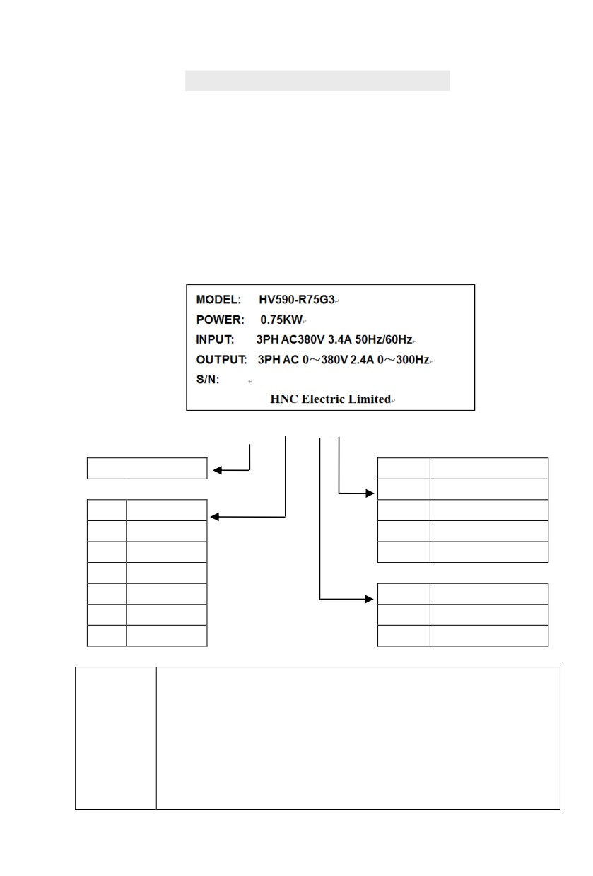
1.1 Nameplate specification
1.2 Model specification
HV590 - R75 G
3
Inverter Series
No.
Voltage
1
Single-phase220V
No.
Adaptation
2
Three-phase220V
R75
0.75kW
3
Three-phase380V
1R5
1.5kW
4
Three-phase480V
011
11kW
018
18.5kW
No.
Inverter Type
110
110kW
G
General type
400
400kW
P
Fan pump type
Users check factory models through P0.00. P type is one lower power than G type.
E.g:If you need 11kw P type, 7.5kw G type could be selected as a replacement. Its input
current is the rated input current (20.5A) of 7.5kw G type, but its rated power is that of 11kw
GP unification
G type, and output current is the rated output current(25A) of 11kw G type.
Model
Though inverter hardware of GP unification is different, there are some optimizations of
description
software parameters for different load types .
P type model is only suitable for pump, fan etc light load models, can not work at the rated
current or more than the rated frequency for a long time.
1
Section I. Product Information
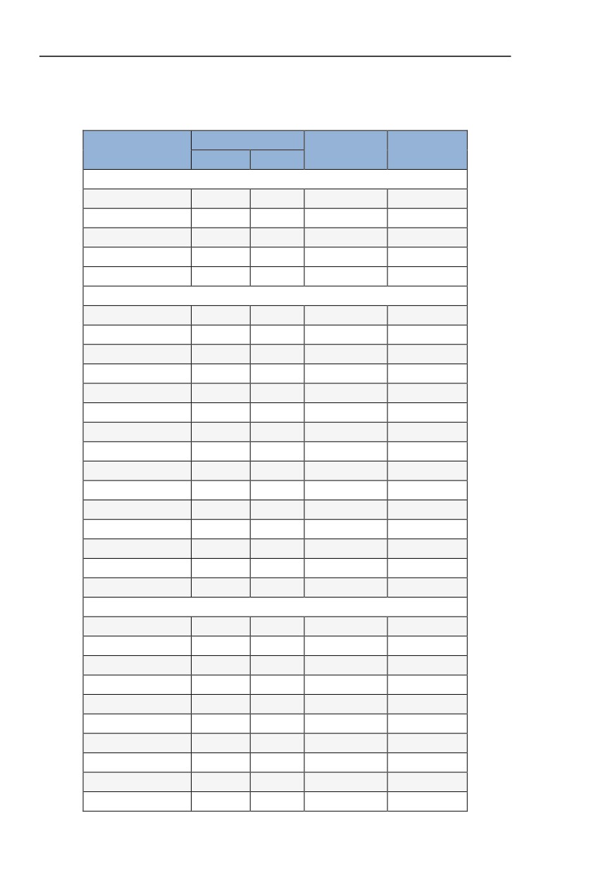
1.3 Product series
Motor adapter
Inverter model
Rated input A
Rated output A
kW
HP
1PH single phase input:AC 220V,50/60Hz
HV590-R40G1
0.4
0.5
5.9
2.5
HV590-R75G1
0.75
1
8.3
4
HV590-1R5G1
1.5
2
14.1
7
HV590-2R2G1
2.2
3
24.2
10
HV590-004G1
4.0
5.5
34.0
16
3PH 3-phase input:AC 220V,50/60Hz
HV590-R40G2
0.4
0.5
4.1
2.5
HV590-R75G2
0.75
1
5.3
4
HV590-1R5G2
1.5
2
8.0
7
HV590-2R2G2
2.2
3
11.8
10
HV590-004G2
4.0
5.5
18.1
16
HV590-5R5G2
5.5
7.5
28.0
25
HV590-7R5G2
7.5
10
37.1
32
HV590-011G2
11
15
49.8
45
HV590-015G2
15
20
65.4
60
HV590-018G2
18.5
25
81.6
75
HV590-022G2
22
30
97.7
90
HV590-030G2
30
40
122.1
110
HV590-037G2
37
50
157.4
152
HV590-045G2
45
60
185.3
176
HV590-055G2
55
70
215.8
210
3PH 3-phase input:AC 380V,50/60Hz
HV590-R75G3
0.75
1
4.3
2.5
HV590-1R5G3
1.5
2
5.2
3.7
HV590-2R2G3
2.2
3
6.0
5
HV590-004G3
4.0
5
10.5
8.5
HV590-5R5G3
5.5
7.5
15.5
13
HV590-7R5G3
7.5
10
20.5
16
HV590-011G3
11.0
15
27.5
25
HV590-015G3
15.0
20
37.1
32
HV590-018G3
18.5
25
41.9
38
HV590-022G3
22
30
49.3
45
2
Section I.
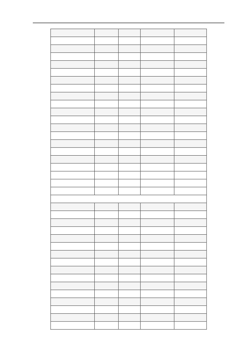
Product Information
HV590-030G3
30
40
65.7
60
HV590-037G3
37
50
80.6
75
HV590-045G3
45
60
96.4
90
HV590-055G3
55
70
117.6
110
HV590-075G3
75
100
166.4
150
HV590-093G3
90
125
184.3
170
HV590-110G3
110
150
226.8
210
HV590-132G3
132
175
268.1
250
HV590-160G3
160
210
321.1
300
HV590-187G3
185
245
368.0
340
HV590-200G3
200
260
406.6
380
HV590-220G3
220
300
442.7
415
HV590-250G3
250
350
503.0
470
HV590-280G3
280
370
555.9
520
HV590-315G3
315
500
650.7
600
HV590-355G3
355
420
734.5
650
HV590-400G3
400
530
787.6
725
HV590-450G3
450
595
846.0
820
HV590-500G3
500
670
885.0
860
HV590-560G3
560
750
990.0
950
HV590-630G3
630
840
1150.0
1100
3PH 3-phase input:AC 460V,50/60Hz
HV590-R75G4
0.75
1
4.1
2.5
HV590-1R5G4
1.5
2
4.9
3.7
HV590-2R2G4
2.2
3
5.7
5
HV590-004G4
4.0
5
9.4
8
HV590-5R5G4
5.5
7.5
12.5
11
HV590-7R5G4
7.5
10
18.3
15
HV590-011G4
11.0
15
23.1
22
HV590-015G4
15.0
20
29.8
27
HV590-018G4
18.5
25
35.7
34
HV590-022G4
22
30
41.7
40
HV590-030G4
30
40
57.4
55
HV590-037G4
37
50
66.5
65
HV590-045G4
45
60
81.7
80
HV590-055G4
55
70
101.9
100
HV590-075G4
75
100
137.4
130
HV590-093G4
90
125
151.8
147
3
Section I. Product Information
HV590-110G4
110
150
216.0
180
HV590-132G4
132
175
220.7
216
HV590-160G4
160
210
264.2
259
HV590-187G4
185
245
309.4
300
HV590-200G4
200
260
334.4
328
HV590-220G4
220
300
363.9
358
HV590-250G4
250
350
407.9
400
HV590-280G4
280
370
457.4
449
HV590-315G4
315
500
533.2
516
HV590-355G4
355
420
623.3
570
HV590-400G4
400
530
706.9
650
HV590-450G4
450
595
760.0
700
HV590-500G4
500
670
865.0
800
HV590-560G4
560
750
970.0
900
HV590-630G4
630
840
1100.0
1000
Table 1-3
1.4 Product shape
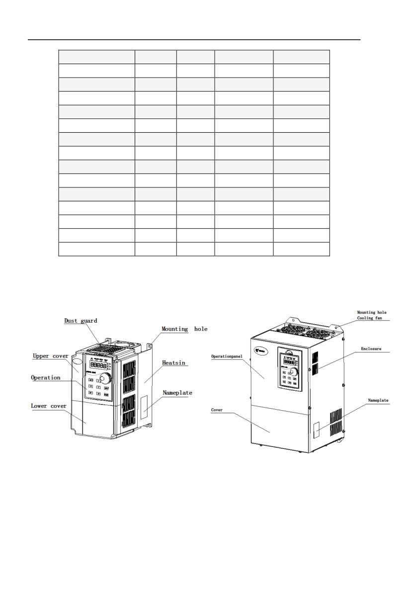
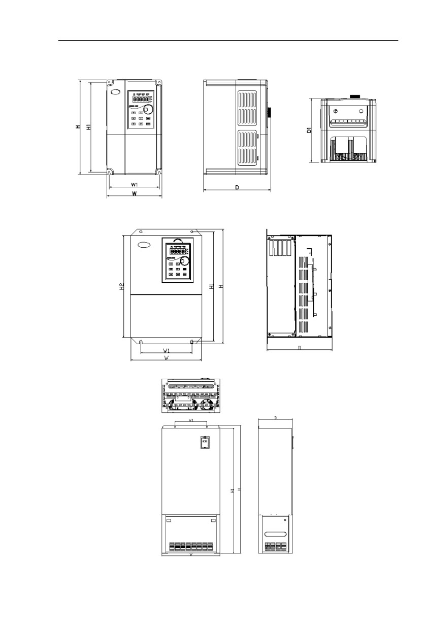
1.4.1 Product Component Name
HV590−R40G1/G2~HV590-2R2G1/G2
HV590-7R5G3 and below power class
HV590-011G3 and above power class
4
Section I. Product Information
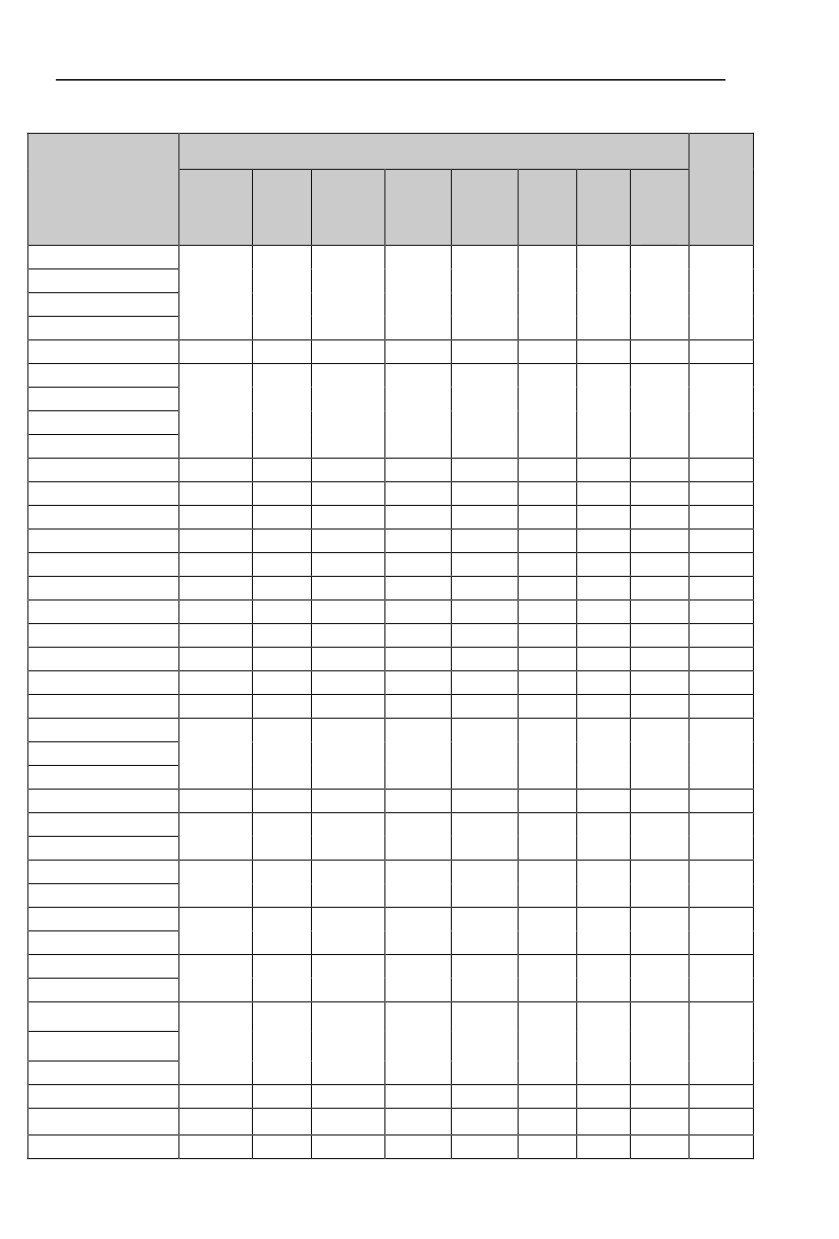
1.4.2 Product Outline, Mounting Dimension, and Weight
HV590−0R4G2~HV590−2R2G2、HV590−R75G3~HV590-7R5G3 and below power class
HV590-011G3~HV590-220G3 power class
HV590-185G3~HV590-400G3
5
Section I. Product Information
Fig.1−4 Product outline and mounting dimension
Shape dimension and nstallation dimension(mm)
Weight
Asse
Shape DIM
(kg
mbly
W
H
D
W1
H1
D1
H2
)
apert
ure
HV590−R40G1
HV590−R75G1
118.5
185
159
106.5
174.5
150
5.5
2.2
HV590−1R5G1
HV590−2R2G1
HV590-004G1
150
258
183.8
136.8
245
175.3
5.5
4.0
HV590−R40G2
HV590−R75G2
118.5
185
159
106.5
174.5
150
5.5
2.2
HV590−1R5G2
HV590−2R2G2
HV590-004G2
150
258
183.8
136.8
245
175.3
5.5
4.0
HV590-5R5G2
210
337
191
150
322.5
298
7
8.7
HV590-7R5G2
210
337
191
150
322.5
298
7
8.7
HV590-011G2
221
380
229.6
163
363.6
341
7
10
HV590-015G2
221
380
229.6
163
363.6
341
7
10
HV590-018G2
285
501
230.2
200
482
460
7
19
HV590-022G2
352
585
274.2
220
559
538
10
35
HV590-030G2
352
585
274.2
220
559
538
10
35
HV590−037G2
352
585
274.2
220
559
538
10
35
HV590−045G2
384
650
310
300
628
600
10
48
HV590−055G2
485
760
316
325
739
713
12
66
HV590−R75G3
HV590-1R5G3
118.5
185
159
106.5
174.5
150
5.5
2.2
HV590-2R2G3
HV590-004G3
118.5
195
169
106.5
184.5
160
5.5
2.6
HV590-5R5G3
175.
150
258
183.8
136.8
245
5.5
4.0
HV590-7R5G3
3
HV590-011G3
210
337
191
150
322.5
298
7
8.7
HV590-015G3
HV590-018G3
221
380
229.6
163
363.6
341
7
10
HV590-022G3
HV590-030G3
285
501
230.2
200
482
460
7
19
HV590−037G3
HV590−045G3
HV590−055G3
352
585
274.2
220
559
538
10
25
HV590−075G3
HV590−090G3
384
650
310
300
628
600
10
48
HV590−110G3
485
760
316
325
739
713
12
66
Wall mounting
533
830
405
325
809
780
12
94
6
Section I. Product Information
HV590−132G3
HV590−160G3
HV590−185G3
Cabinet installation
HV590−132G3
533
1212
405
325
1191
780
12
150
HV590−160G3
HV590−185G3
Cabinet installation
HV590−200G3
638
1402
374
350
1372
14
175
HV590−220G3
Cabinet installation
HV590−250G3
700
1627
460
520
1592
14
253
HV590−280G3
HV590−315G3
HV590−355G3
800
1772
460
520
1737
14
300
HV590−400G3
HV590−450G3
HV590−500G3
1200
2000
568
14
400
HV590−560G3
HV590−630G3
HV590−R75G4
HV590-1R5G4
118.5
185
159
106.5
174.5
150
5.5
2.2
HV590-2R2G4
HV590-004G4
118.5
195
169
106.5
184.5
160
5.5
2.6
HV590-5R5G4
175.
150
258
183.8
136.8
245
5.5
4.0
HV590-7R5G4
3
HV590-011G4
210
337
191
150
322.5
298
7
8.7
HV590-015G4
HV590-018G4
221
380
229.6
163
363.6
341
7
10
HV590-022G4
HV590-030G4
285
501
230.2
200
482
460
7
19
HV590−037G4
HV590−045G4
HV590−055G4
352
585
274.2
220
559
538
10
25
HV590−075G4
HV590−090G4
384
650
310
300
628
600
10
48
HV590−110G4
485
760
316
325
739
713
12
66
Wall mounting
HV590−132G4
533
830
405
325
809
780
12
94
HV590−160G4
HV590−185G4
Cabinet installation
HV590−132G4
533
1212
405
325
1191
780
12
150
HV590−160G4
7
Section I. Product Information
HV590−185G4
Cabinet installation
HV590−200G4
638
1402
374
350
1372
14
175
HV590−220G4
Cabinet installation
HV590−250G4
700
1627
460
520
1592
14
253
HV590−280G4
HV590−315G4
HV590−355G4
800
1772
460
520
1737
14
300
HV590−400G4
HV590−450G4
HV590−500G4
1200
2000
568
14
400
HV590−560G4
HV590−630G4
8
Section I. Product Information
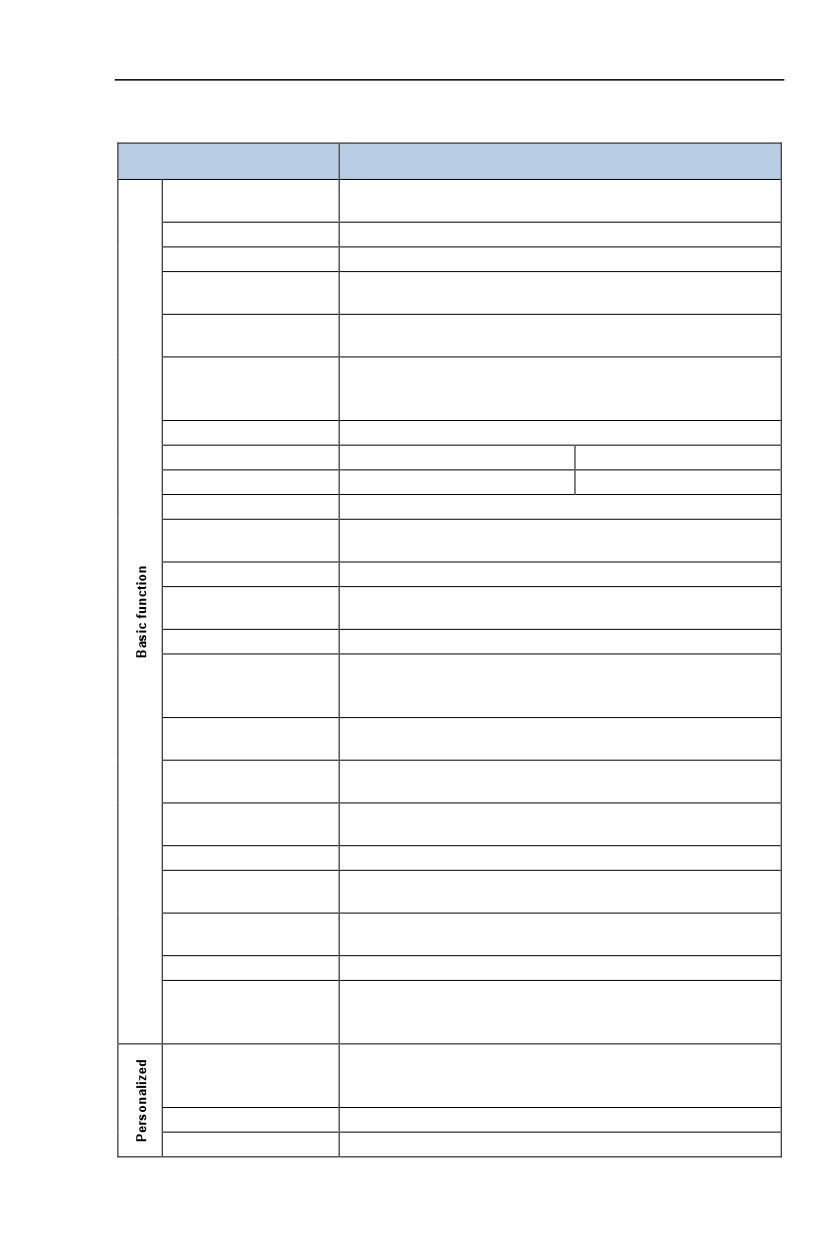
1.5
Standard specification
Item
Specifications
High performance of current vector control technology to realize
Control system
asynchronous motor and synchronous motor control
Drive performance
High efficiency driving for induction motor and synchronous motor
Maximum frequency
Vector control:0~300HzV/Fcontrol:0~3200Hz
0.5k~16kHz;thecarrierfrequency will be automatically adjusted
Carrier frequency
according to the load characteristics
Digital setting: 0.01Hz
Input frequency resolution
Analog setting: maximum frequency ×0.025%
Open loop vector control(SVC)
Control mode
Closed loop vector control(FVC)
V/F control
Startuptorque
Type G:0.5Hz/150%(SVC);0Hz/180%(FVC)
Speed range
1:100(SVC)
Speed range
Speed stabilizing precision
±0.5%(SVC)
Speed stabilizing precision
Torque control precision
±5%(FVC)
G type: rated current 150% -1 minute, rated current 180% -3
Over load capability
seconds;
Torque boost
Auto torque boost function;Manual torque boost 0.1%~30.0%
LinearV/F,Multi-point V/Fand Square V/F curve (power of 1.2, 1.4, 1.6,
V/Fcurve
1.8, 2)
V/F separation
In 2 ways:separation ,semi seperation
Straight line or S curve acceleration and deceleration mode.
Acc. /deccurve
Four kinds of acceleration and deceleration time. Acceleration and
deceleration time range between 0.0s to 6500.0s
DC brake frequency:0.00Hz to maximum frequency,brake time:
DC brake
0.0s to 36.0s, and brake current value: 0.0% to 100.0%.
Jog frequency range:0.00Hz~50.00Hz. Jog acceleration/deceleration
Jog control
time 0.0s~6500.0s.
Simple PLC and MS speed
It can realize at maximum of 16 segments speed running via the built-
running
in PLC or control terminal.
Built-in PID
It is easy to realize process-controlled close loop control system
Auto voltage regulation
It can keep constant output voltage automatically in case of change of
(AVR)
network voltage.
Over-voltage/current stall
It can limit the running voltage/current automatically and prevent
control
frequent over-voltage/current tripping duringthe running process
Quickcurrent limit
Minimize the over-current fault,protect normal operation of the inverter
"Excavators" characteristics,automatically limit torque during
Torque limit & control
operation,prevent frequent over-current trip;
Closed loop vector mode can realize the torque control.
When instantaneous power off,voltage reduction is compensated
Instantaneous stop
through load feedback energy,which could make inverter keep running
non-stop
in a short period of time.
Rapid current limit
To avoid inverter frequent over-current fault.
Virtual IO
5 groups of virtual DI,DO to realize simple logic control
9
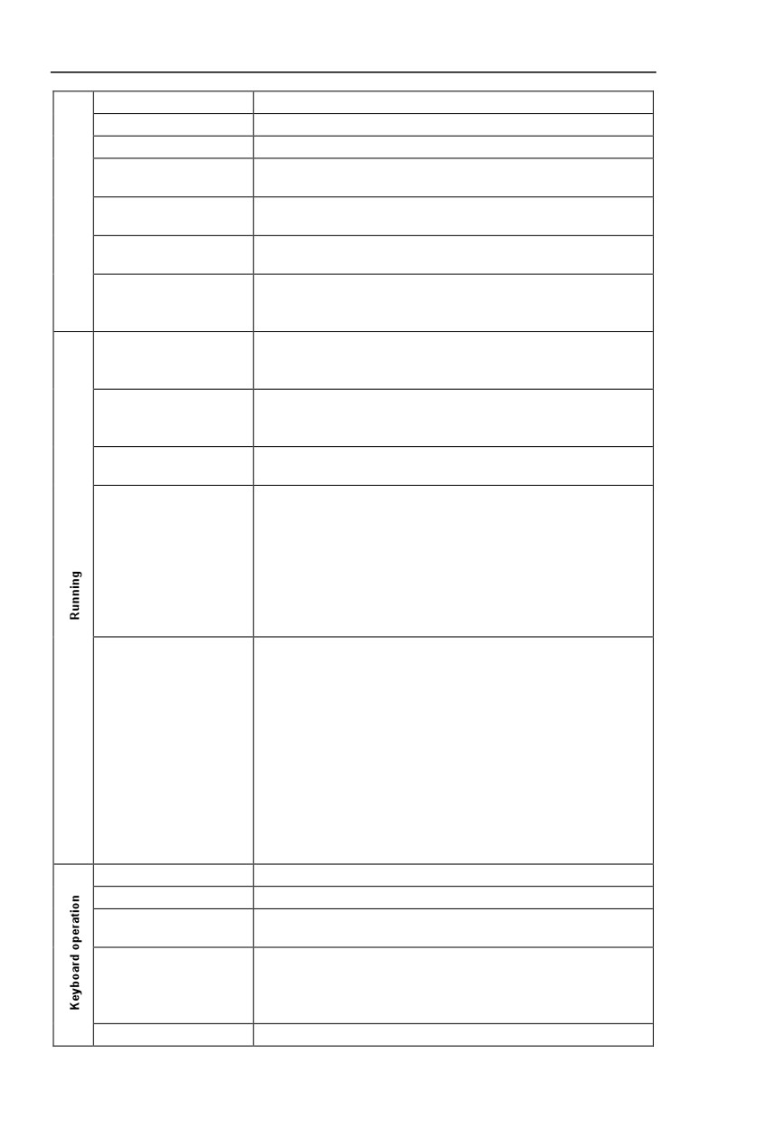
Section I. Product Information
Timingcontrol
Timing control function:settimerange0Min~6500.0Min
Multiple motor switch
4 groups of motor parameter,which can realize 4-motor switch control
Multi-threaded bus support
Support 3 kinds of field bus:RS485, Profibus-DP, CANopen
Select optional H5PC1 analog input AI3x can accept the motor
Motor overheat protection
temperature sensor input(PT100、PT1000)
Support difference,open collector, UVW, rotary transformer, sine
Multi-encoder support
cosine encoder etc.
Select optional user programmable card,which can realize secondary
Programmable PLC
development,programming mode compatible with Drino PLC.
Support inverter parameter operation and virtual oscilloscope
Excellent backend software
function.Inverter internal state graphic monitor can be realized
through virtual oscilloscope.
Three types of channels:operation panel reference,control terminal
Running command channel
reference and serial communication port reference.These channel
scan be switched in various modes.
There are totally eleven types of frequency sources, such as digital
Frequency source
reference, analog voltage reference, analog current reference, pulse
reference, MS speed, PLC, PID and serial port reference.
11 kinds of auxiliary frequency source which can flexible achieve
Auxiliary frequency source
auxiliary frequency tuning, frequency synthesis
Standard:
There are 6 digital input terminals,DI5 can be used as100kHz high-
speed input pulse.
2 analog input terminals which can be used as 0-10V voltage input or
Input terminal
0~20mA current input.
Extended function:
4 digital input terminals,
1analog input terminals support-10~10V voltage input &PT100\PT100
Standard:
1 digital output terminals, Y1 is high-speed pulse output terminal (can
be choosen as open circuit collector type), support 0~10kHz square
wave signal;
2 relay output terminal;
2 analog output terminals, support 0~20mA output current or 0~10V
Output terminal
output voltage;
Extended function:
2 digital output terminal;;
1 analog output terminal, support 0~20mA output current or 0~10V
output voltage.
LED display
Realizeparameter setting,statusmonitoringfunction
Keyboard potentiometer
Equipped with keyboard potentiometer or coding potentiometer
Realize button locking,define operation range for part of buttons to
Key lock&function selection
prevent operation fault.
It can implement power-on motor short-circuit detection,input/output
phase loss protection, over current protection,over voltage
Protection function
protection,under voltage protection,overheating protection and overload
protection.
Optionalparts
Liquid crystal display operation panel, brake component, multi-
10

Section I. Product Information
function extended card (1.IO extended card 2.user programmable
card), RS485 communication card, Profibus-DP communication card,
CANopen communication card, differential input PG card, UVW
differential input PG card, rotating inverter PG card, OC input PG
card.
Indoor,and befreefromdirectsunlight,dust,corrosivegas, combustible
Using place
gas,oilsmoke, vapor,driporsalt.
Altitude
Below 1000m
-10 ć to +40 ć (Derating use when under ambient temperature of
Ambient temperature
40 ć to 50 ć)
Humidity
Less than 95%RH, without condensing
Vibration
Less than 5.9 m/s2(0.6g)
Storage temperature
-20ć~+60ć
Table:1-5.1
11
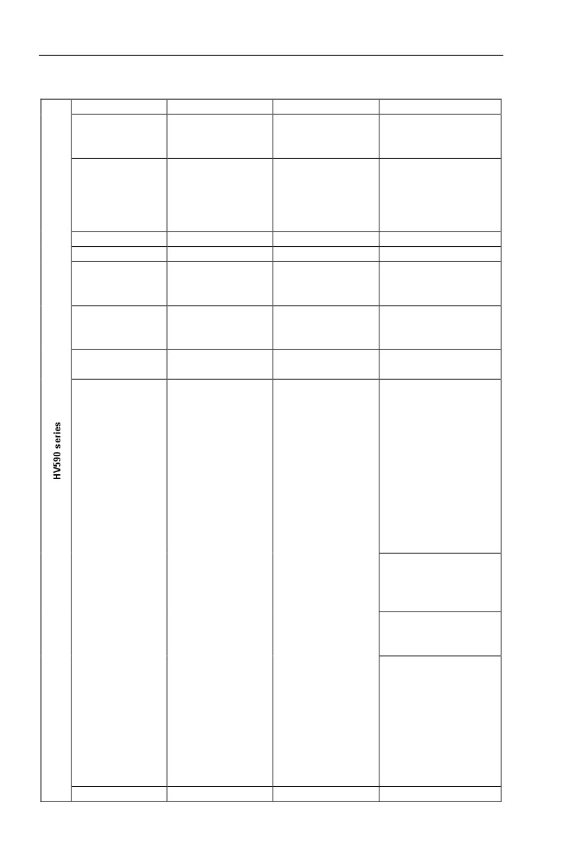
Section I. Product Information
1.6
Interface configuration
Interface
Standard
Optional 1
Optional 2
DI7~DI10
DI7~DI8
Input DI
DI1~DI6
Multi-function card :
Communication card:
H5PC1
H5RS485
1 way collector
1 way collector:
1 way collector output:
output:DO1
ExtendedDO2
Extended DO2
Output DO
2 way relay:
1 way Multi-function
Communication card:
TA1,TB1,TC1
card:H5PC1
H5RS485
TA2,TB2,TC2
High speedDI
DI5
-
-
High speedY
Y1
-
-
Rs485
communication
Rs485communication
card
CAN-OPEN:
CAN-LINK:
CAN
-
communication card
communication card
communication card
H5CCANO
H5CCANL
Profibus-DP
Communication card:
-
-
communication card
H5CPDP
H5PG1
Differential input PG
card,without dividing
frequency output;
OC input PG card,
without dividing
frequency output;
Optional
5V,12V,24V.Please
provide voltage and
pulse input information
when ordering.
V6-PG3
UVW Differential input PG
PG interface
-
-
card,without dividing
frequency output 5V
V6-PG4
Rotating transformer PG
caed
V6-PG5
OC input PG card
With 1:1 dividing frequency
output;
Optional
5V,12V,24V.Please
provide voltage and
pulse input information
when ordering.
Keyboard
Single LED
12

Section I. Product Information
keyboard:J5P1
6 groups of parameter
can be stored
Potentiometer
4-pump constant
pressure water
Constant pressure
-
supply
-
water supply board
4-pump soft start
control panelH5WS
Table:1-6.1
If you need accessories in the table, please declare in order.
13
Section II. Installation &Wiring
2.1 Use of the environment
1) Ambient temperature-10ć~40ć.
2) Avoid electromagnetic interference and keep the unit away from the source of interference.
3) Prevent dropping water, steam, dust powder, cotton fiber or fine metal powderfrominvasion.
4) Prevent oil, salt and corrosive gas from entering it.
5) Avoid vibration. Vibration should be less than 0.6G. Keep away from punching machine etc.
6) Avoid high temperature, moisture or being wetted due to raining, with the humidity below
95%RH (non-condensing).
7) Prohibit the use in the dangerous environment where inflammable or combustible or explosive
gas, liquid or solid exists.
2.2 Handling and installation
※ When transporting inverter, right lifting tools are required to prevent inverter from
damaging.
※ The number of stacked box of the inverter are not permitted higher than the limit.
※ Please don’t run the inverter if there is damage or lacking of components.
※ Do not place heavy objects on the frequency inverter.
※ Please prevent screw, cable pieces or other conductive objects or oil etc
inflammableobjects invading the frequency inverter.
※ Do not make it fall or have a strong impact.
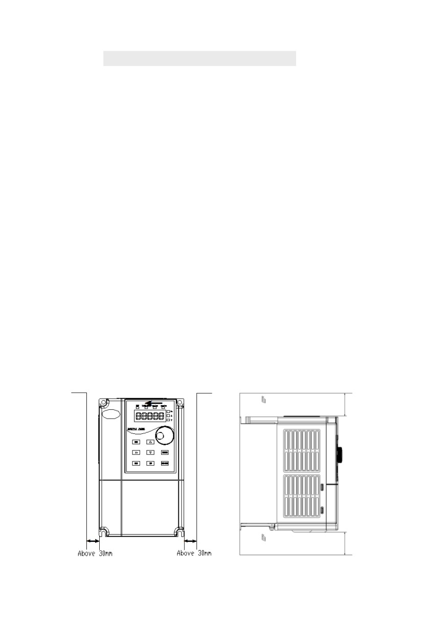
※ Confirm if the installation location and object could withstand the weight of the
inverter. The frequency inverter must be installed by wall hooking、inYor room
withadequate ventilation, with enough space left between it and the adjacent objects
or retaining board (walls) around, as shown in the picture below:
Above 120mm
Air circulation position
Above 120mm
Air circulation position
Fig. 2-2.1
14
Section II. Installation &Wiring
Heat dissipation problems should be concerned when doing mechanical installation, please
mind rules belows:
1) Mounting space is shown in 2-2.1, which could ensure the heat sinking space of the
inverter. However, the heat sinking of other devices in the cabinet shall also be considered.
2) Install the inverter vertically so that the heat may be expelled from the top.However, the
equipment cannot be installed upside down. If there are multiple inverters in the cabinet,
parallel installation is better. In the applications where up-down installation is required,
please install the thermal insulating guide plate referring to the Fig. 2-2.2 for standalone
installation and up-down installation.
3) Installing support must be flame retardant materials.
4) It is suggested that cooling cabinet be put outside at places where powder dust exists.
Space inside the sealed cabinet shall be large as much as possible.
15
Section II. Installation &Wiring
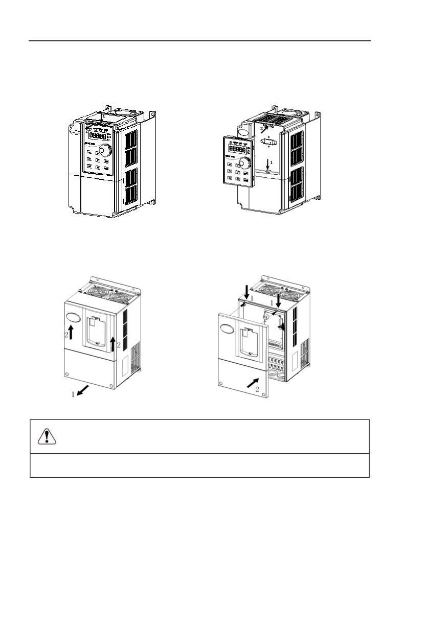
2.3 Lower cover removable and installation
Series below 7.5kW employ the plastic enclosure, refer to Fig. 2-3.1 for the removal of the
lower cover of the plastic enclosure, users may directly upturn it for 90 degrees.
Fig. 2-3.1
Series above 11KW employ sheet-metal enclosures. Refer to Fig. 2-3.2 for the removal of the
upper cover of the sheet-metal enclosure. Loosen the screws of the lower cover directly with tools.
Fig. 2-3.2
Danger
Whenremovingthelowercover,avoidthefallingofthelowercover,which maycause human injuryor
damage tothe equipment.
16
//////////////////////