HV610 Series Frequency Inverter. User Manual (2021 V0.2 version) - page 1
Precautions for safety
The safe operation of the product depends on proper transportation, installation, operation and maintenance.
Please pay attention to safety tips before carrying out these tasks.
Safety symbol description
In this instruction manual, safety matters are divided into the following two categories:
When it is used incorrectly, it will cause danger and may lead to personal injury and death.
Danger
When it is used incorrectly, it will cause danger and may cause slight or moderate personal injury
of equipment damage.
Caution
2
Table of contents
Chapter I Purchase inspection
5
F1 Group first motor parameters
67
1.1 Inspection items
5
F2 Group motor vector control parameters
69
1.2 Nameplate description
6
F3 Group V/F control parameters
70
1.3 Description of components of frequency inverter... 7
F4 Group output terminals
74
Chapter II Installation wiring
8
F5 Group input terminals
80
2.1 Mechanical installation
8
F6 Group start-stop control
92
2.1.1 Installation Conditions
8
F7 Group torque control
97
2.1.2 Installation Space
9
F8 Group auxiliary function
98
2.2 Electrical Installation
10
F9 Group failure and protection
104
2.2.1 Frequency inverter main circuit terminal
FA Group process control PID function
109
description
10
FB Group 2 motor parameters
114
2.2.2 Main circuit wiring method and wiring matters
FC Group multi-segment instruction and simple PLC
needing attention:
11
function
115
2.2.3 Frequency inverter control loop terminal
FD Group communication parameters
120
description
12
FE Group user-defined function code
120
2.2.4 Standard wiring diagram of frequency inverter15
FF Group control optimization parameters
120
2.2.5 Control circuit wiring mode
16
E0 Group fault record
120
Chapter III Process operation
19
P2 Group AIAO correction
122
3.1 Operation keyboard and display interface
19
U0 Group monitoring parameter group
124
3.2 Indicator light indicates run
19
Chapter VI Abnormal diagnosis
129
3.3 key function description
20
6.1 Fault alarm and countermeasures
129
3.4 Methods of checking and modifying function codes20
6.2 Matters needing attention in commissioning:
132
3.5 Two quick search modes for function code
6.3 F0.01 = 2 ( V/F mode), common problem solving
parameters there
21
methods
133
3.6 Commissioning
21
6.4 Fault analysis and countermeasures
133
3.7 Motor characteristic parameter setting and self -
Chapter VII Maintenance
137
learning
21
7.1 Maintenance and repair
137
Chapter IV Functional parameters
24
7.1.1 Routine maintenance
137
4.1 Summary of basic functional parameters
24
7.1.2 Regular maintenance
138
4.2 Summary table of monitoring parameters
55
7.1.3 Replacement of vulnerable parts of frequency
Chapter V Description of parameters
57
inverter
138
F0 Group basic function group
57
7.2 Storage
139
3
Chapter VIII Peripheral equipment
140
8.1 Peripheral equipment and optional parts connection
diagram
140
8.2 Functional description of peripheral equipment.. 140
8.2.1 No fuse circuit breaker and contactor
141
8.2.2 AC input reactor
142
8.2.3 AC output reactor
142
8.2.4 Selection of energy consumption braking unit
and braking resistance
143
8.2.5 External DC reactor
145
8.2.6 Radio noise filter
145
Chapter IX Quality Assurance
148
9.1 Quality commitment
148
Additional instructions
149
Appendix A Introduction of Communication
150
Appendix B Technical specification for HV610 series
frequency inverters
161
Appendix I general purpose keyboard dimensions and
mounting dimensions
163
Appendix II Plastic shell dimensions and mounting
dimensions
164
Appendix III dimensions and mounting dimensions of
sheet metal machines
165
List of dimensions and mounting dimensions
166
Appendix D HV610 series inverter specifications
169
Constant pressure control solution Case V0.1 for water
pump and fan
172
1.1. Overview
172
2.1 Two types of pressure sensors for pump and fan
control
172
3.1 Control wiring diagram
172
3.2 Setting parameters
172
4.1 The sleep wake-up function
173
Inquiry method of state parameters
174
Warranty Agreement
176
4
Chapter I Purchase inspection
Danger
z
Do not install the frequency inverter if it is damaged, water intake, parts missing or
damaged
Caution
z
Handle with care and avoid falling shock.
z
Do not use your hands to pull or touch any components of the machine to avoid
short-circuit accidents or electrostatic damage
1.1 Inspection items
Although the Company's products have been strictly inspected before leaving the factory, due to transportation
or unforeseen circumstances, please carefully inspect the products after purchase.
The items and methods that must be checked and confirmed are as follows:
Confirmation content
Confirmation method
Please confirm the nameplate on the side of the
Is it consistent with the goods ordered
machine
Check the overall appearance and check for damage
Are there any parts broken or damaged
during transportation
Are there any loose fastening parts such as
If necessary, use a screwdriver to check it
screws
Instructions, certificates of conformity and other
Operating instructions and corresponding accessories
accessories
If there is any bad situation or abnormality, please contact the agent or the Company's customer service center.
5
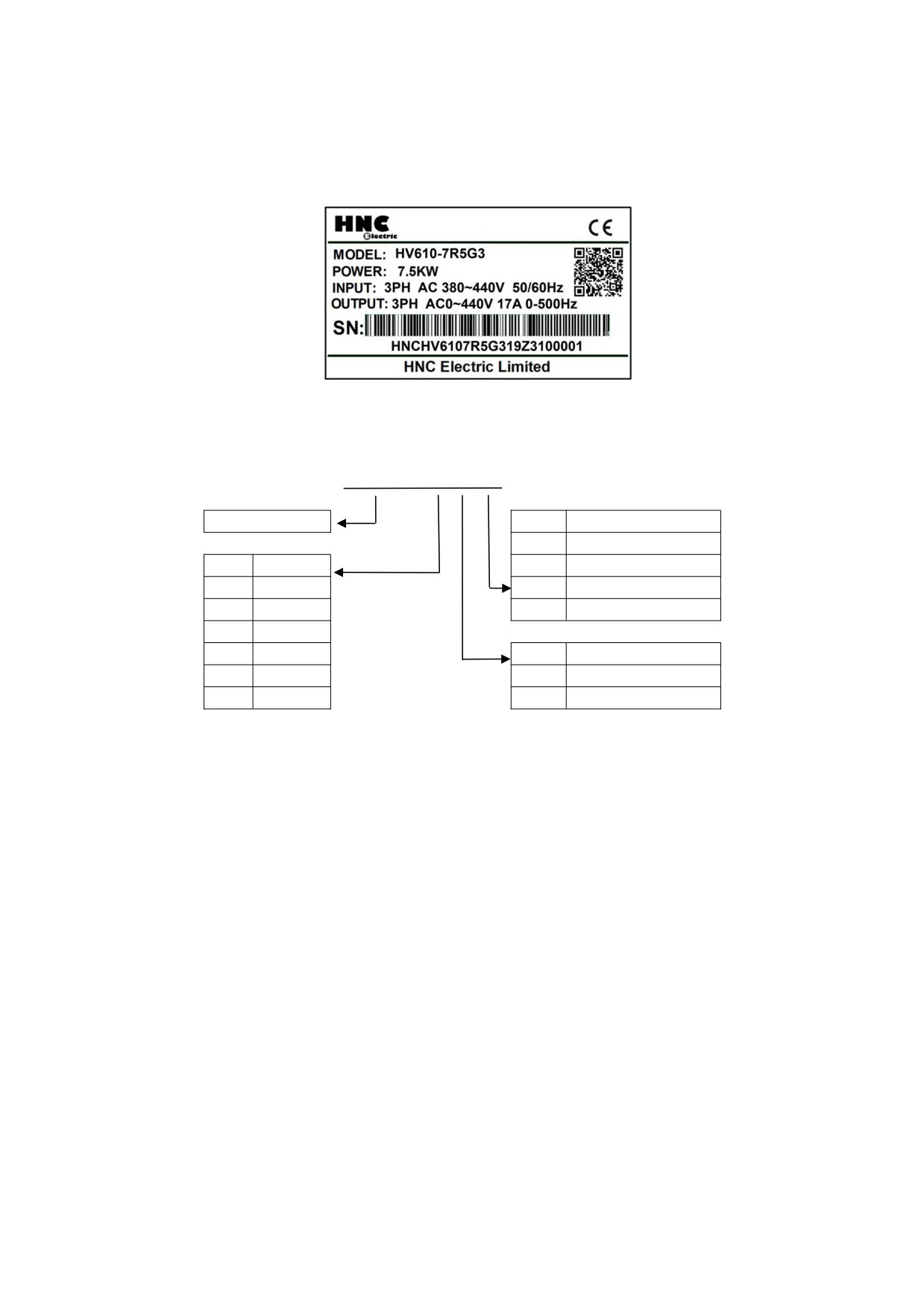
1.2 Nameplate description
z
Nameplate data
Description of frequency inverter model
HV610 - 7R5 G
3
Inverter Series
No.
Voltage
1
Single-phase220V
No.
Adaptati
2
Three-phase220V
R75
0.75kW
3
Three-phase380V
7R5
7.5kW
4
Three-phase460V
011
11kW
018
18.5kW
No.
Inverter Type
110
110kW
G
General type
400
400kW
P
Fan pump type
Note:
G1 input voltage range: Single-phase AC220V±15%
G2 input voltage range: Three-phase AC220V±15%
G3 input voltage range: Three-phase AC 380~440 (-15%~+10%)
G4 input voltage range: Three-phase AC 460~480 (-15%~+10%)
Note of DC reactor:
G1: No interface
G2: 18kw and below, no interface;
22kw~200kw, interface is optional, 220kw built-in DC reactor.
G3: 37kw and below, no interface;
45kw~400kw, interface is optional, 450kw and above built-in DC reactor.
G4: 37kw and below, no interface;
45kw~400kw, interface is optional, 450kw and above built-in DC reactor.
6
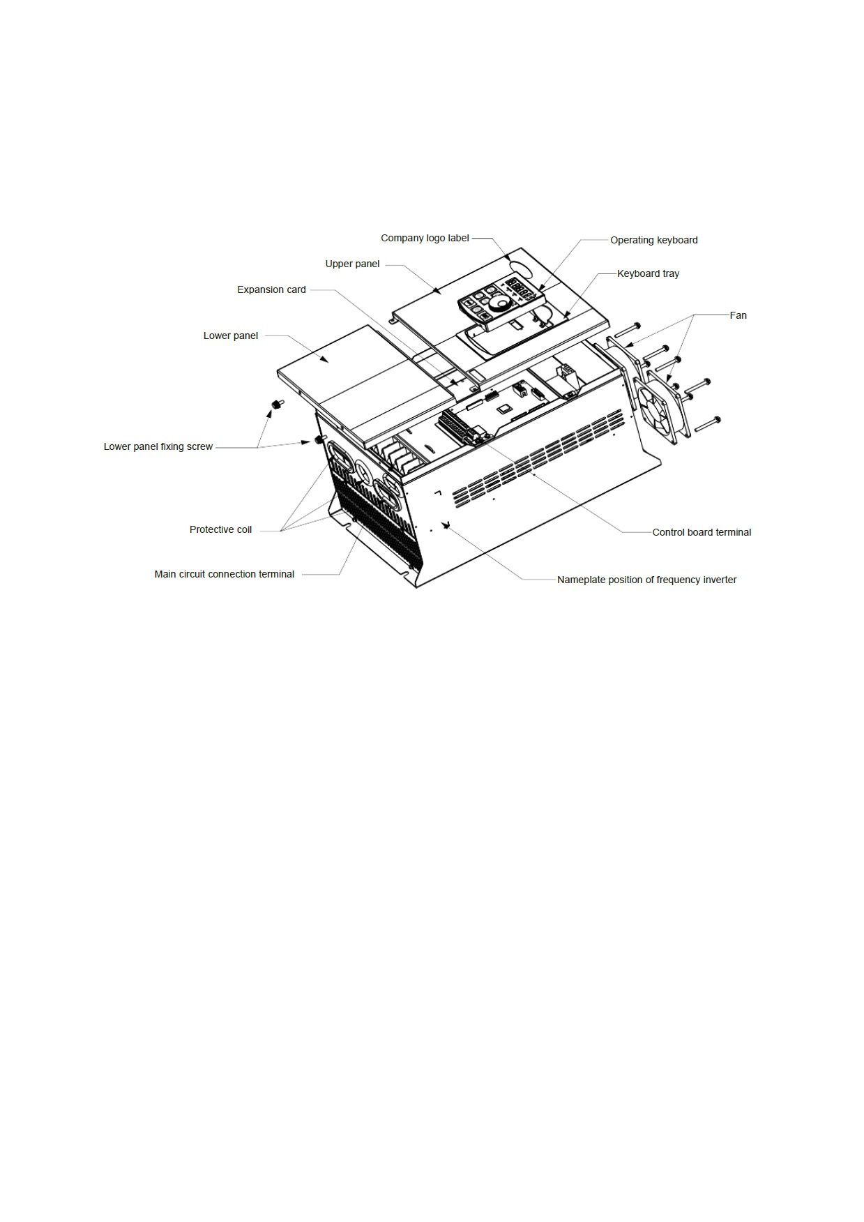
1.3 Description of components of frequency inverter
Company logo label
Fan
Lo
Lower panel fixing screw
Protec
minal
Main circuit co
er
Take HV610-022G3 as an example
7
Chapter II Installation wiring
2.1 Mechanical installation
Danger
z
Please install it on the refractory material board such as metal.
z
Installed on flammable materials, there is a risk of fire.
z
When two or more frequency inverters are installed in the same control cabinet please set
up a cooling fan and keeps the air temperature at the air inlet below 40 °C.
z
Due to overheating, fire and other accidents will occur.
Caution
z
Please support the bottom of the machine body when carrying. Please use the machine
with lifting rings. For machines that do not have rings, do not only take panels to prevent
injury.
Please install the frequency inverter in the following application places and maintain the appropriate conditions.
2.1.1 Installation Conditions
1) It is the best to have a well ventilated room.
2) Ambient temperature - 30 °C ~ + 40 °C, bare machine with - 30 °C ~ 50 °C.
3) The humidity is less than 90 % RH, and there is no water splashing or dripping.
4) The installation foundation is firm and not easy to be vibrated, and its vibration is not more than 0.5g.
5) Avoid direct sunlight.
6) Avoid installing in places with corrosive and combustible gases in the air.
7) Avoid installing in places with dust, oil stain and polymetallic dust in the air.
8) Avoid installing in places with electromagnetic interference sources.
9) Below 1000 meters above sea level. High altitude areas should be reduced in use, or the ambient
temperature should be reduced by 0.5 °C for every 100 meters above sea level.
8
2.1.2 Installation Space
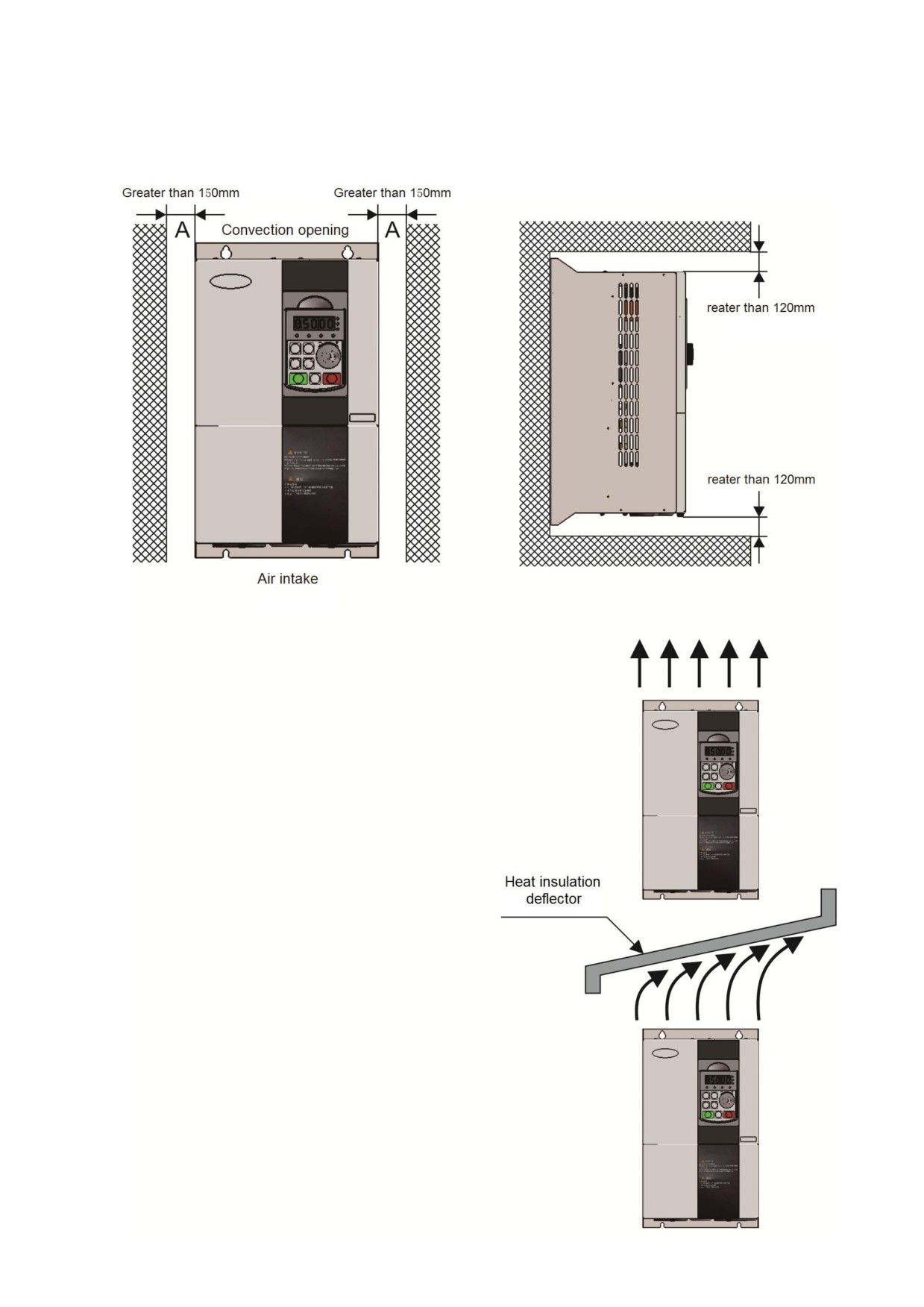
The installation diagram of the frequency inverter is as follows:
Monomer installation: the size of A is larger than 150
mm, because the upper and lower directions are air ducts,
the space distance should be increased.
When installing up and down: when installing the
frequency inverter up and down, please press the heat
insulation baffle as shown in the figure on the right.
The mechanical installation needs to pay attention to
the heat dissipation problem, so please pay attention to
the following points:
z Please install the frequency inverter vertically so
that heat can be dissipated upwards. If there are more
frequency inverters in the cabinet, it is better to install
them in parallel. For occasions requiring mounting up and
down, please refer to the schematic diagram on the right
side to install the heat insulation deflector.
z For applications with metal dust, it is recommended
to install the radiator outside the cabinet. At this time, the
space inside the fully sealed cabinet should be as large as
possible.
z Mounting bracket must be flame retardant material
9
2.2 Electrical Installation
Danger
z
Before wiring, please make sure that the input power supply is cut OFF to avoid electric
shock and fire.
z
To ensure safety, grounding terminals must be reliably grounded according to the
specification requirements.
z
Do not connect the input power supply to the U, V, and W terminals of the output by
mistake.
Caution
z
Please confirm whether the AC power supply is consistent with the rated input voltage of
the frequency inverter
z
Do not connect the electromagnetic switch and contactor to the frequency inverter input
circuit.
z
Before peripheral equipment is connected to the frequency inverter, it must be confirmed
that its insulation to ground is in good condition.
z
Do not conduct insulation withstand voltage test on the frequency inverter so as not to
damage the devices inside the machine.
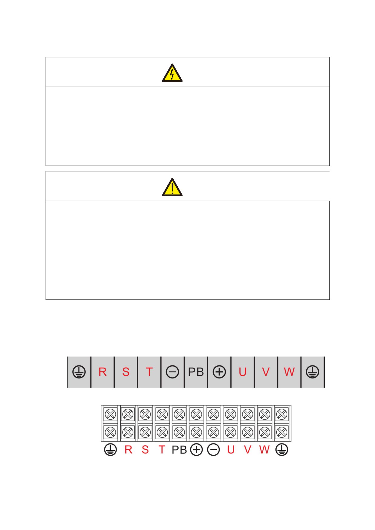
2.2.1 Frequency inverter main circuit terminal description
1) Main loop terminals below 22kw:
2)30kw / 37kw frequency inverter main circuit terminal:
10
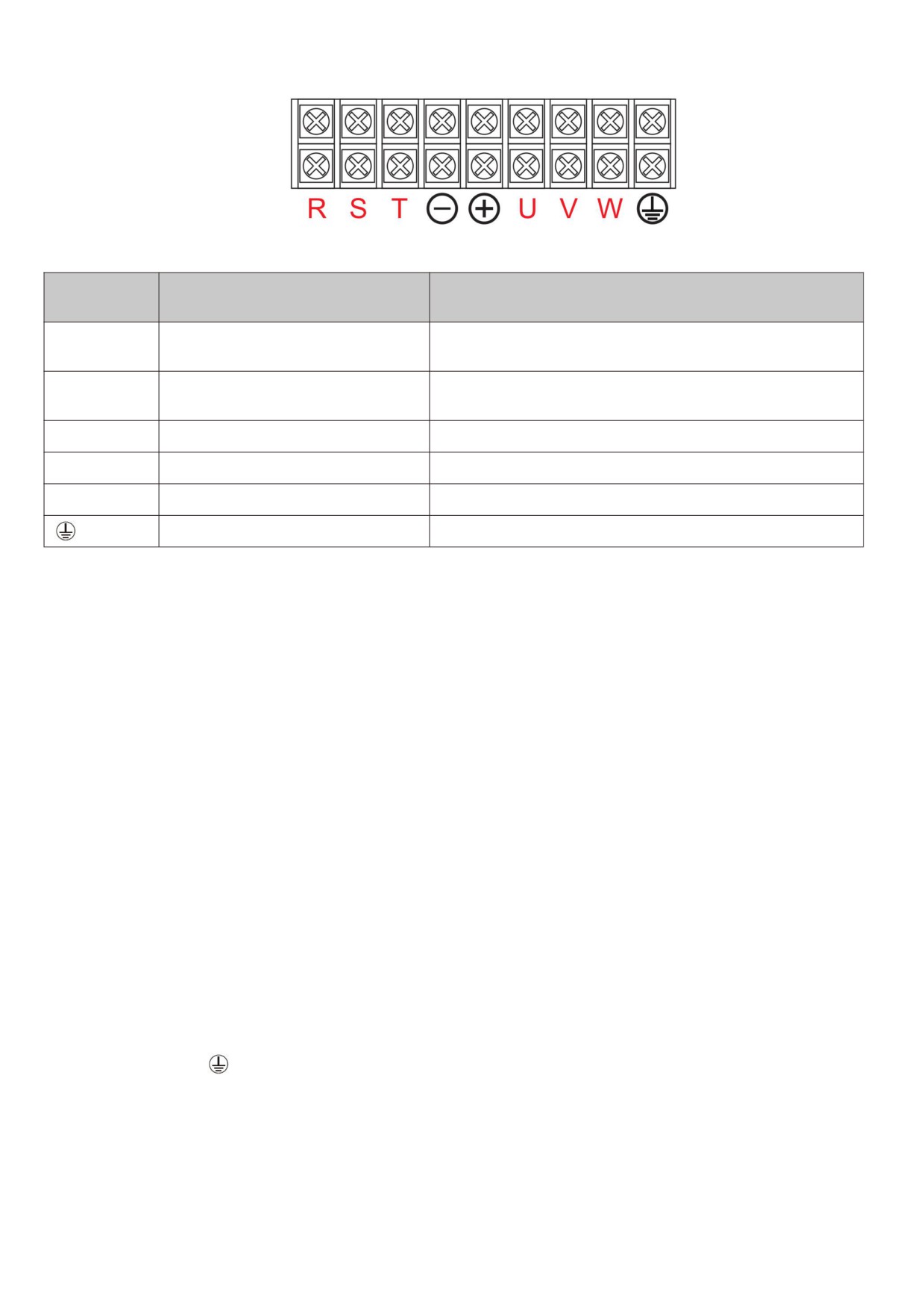
3) Main loop terminal of frequency inverter of 45kw and above:
Description of main circuit terminal of three-phase frequency inverter
Terminal
Name
Description
marking
Three-phase power supply input
R,S,T
Connection point for AC input three-phase power supply
terminal
Negative and positive terminals of
㊀,㊉
Common DC bus input point
DC bus
㊉,PB
Brake resistor connection terminal
Brake resistance connection point
㊉,P+
DC reactor connection terminal
U,V,W
frequency inverter output terminal
Connecting three-phase motor
Earth terminal
Earth terminal
2.2.2 Main circuit wiring method and wiring matters needing attention:
z
Input power supply R, S, T: input side wiring of frequency inverter, no phase sequence requirements.
z
Terminals ⊕ and Θ DC bus: please note that there is still a high residual voltage in the DC bus just after the
power failure, so it must wait at least 15 minutes later, or confirm that the voltage is less than 36 V before
touching, otherwise there is danger of electric shock.
z
When selecting an external brake unit, pay attention to the positive and negative polarity, which cannot be
reversed, otherwise, the frequency inverter will be damaged or even damaged by fire. In order to prevent stray
inductance from affecting the braking effect, the wiring length of the braking unit should not exceed 5m.
Twisted pair or tight double wire should be used for parallel preparation, and non-inductive resistance should
also be used for braking resistance.
z
Brake resistance connection terminals ⊕, PB : 22kW G type machines and the following specifications are
models with built-in brake function. The wiring precautions for the brake resistance are the same as those for the
output side U, V, and W: the frequency inverter capacitors or surge absorbers cannot be connected to the output
side of the frequency inverter, otherwise, the frequency inverter will often be protected or even damaged. When
the motor cable is too long, due to the influence of the distributed capacitance, it is easy to generate electrical
resonance, thus causing the motor insulation to be damaged or causing a large leakage current to cause over
current protection of the frequency inverter. When the length of the motor cable is greater than 100 m, an AC
output reactor must be installed.
z
Earthling terminal
: the terminal must be reliably grounded, and the resistance value of grounding wire must
be less than 0.1Ω. Failure to do so will result in work of equipment is abnormal or even damaged Do not share
the earthling terminal with the N terminal of the zero line of the power supply.
z
See [2.2.4 inverter standard wiring diagram] for wiring method].
z
Frequency inverter on/off operation should avoid frequent power-up and power-down operations (less than twice
per minute) or direct start-up operations of the frequency inverter through contactors. Refer to the following table
for air switch, contactor and conductor section.
11
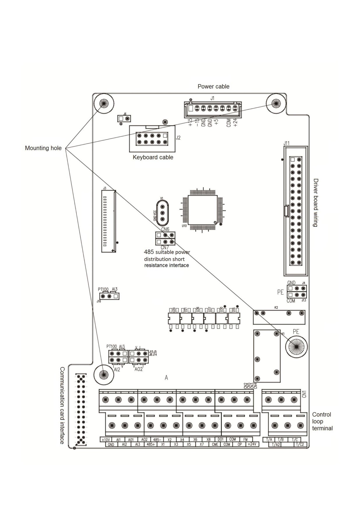
2.2.3 Frequency inverter control loop terminal description
12
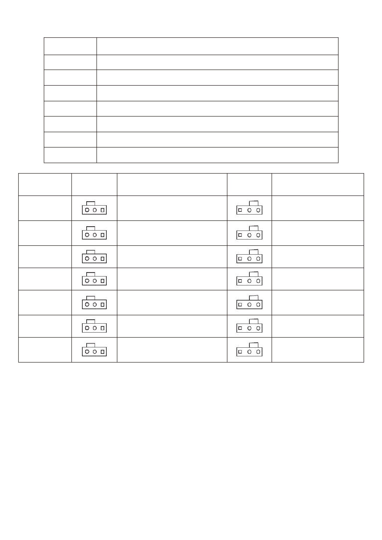
HV610 jumper description: and its function table
Jumper number
Description
J4
GND ground terminal
J5
AO1 output terminal selection - voltage / current
J14
AO2 output terminal selection - voltage / current
J13
COM ground terminal
J8
AI2 analog input terminal selection - voltage / current
J15 & J16
AI3 analog input terminal selection - temperature /AI, to be used in combination
CN6 & CN7
485 communication terminal resistance, need to be used in combination
Jumper serial
Jumper
Functional Description
Jumper
Functional Description
number
position
position
J4
0.1 u F is connected between
-
GND and PE
J5
AO1 analog DC 0 ~ 10 v output
AO1 analog DC 0 ~ 20 m a
output
J8
AI2 analog DC 4 m a ~ 20 m a
AI2 analog DC 0~ 10V
J13
0.1 u f between COM and PE
-
J14
AO2 analog 4 m A ~ 20m A
AO2 analog DC 0~ 10
V
output
output
J15 & J16
AI3 terminal is analog DC
AI3 terminal for PT100 input
0V~ 10 V
CN6 & CN7
Connect 485 communication
Terminal resistance not
terminal resistance
connected
13

Terminal
Category
Terminal name
Functional Description
symbol
External provide
+ 10v power supply the maximum output
External
current is 10mA, which is generally used as the working power
+10V-GND
connection + 10v
supply for external potentiometer and the resistance value of
power supply
potentiometer ranges will be from 2.5k ~ 5kΩ
External provide + 24v power supply, generally used as working
External
power supply for digital input and output terminals and
Power supply
+24V-COM
connection + 24v
maximum output current for external sensor power supply:
power supply
200mA
Select + 24V or OP connection through the short connector 1
External power
on the control panel, and the factory defaults to
+
24v
OP
input terminal
connection. When X1 ~ X7 are driven by external signals, OP
needs to be connected to external power supply.
Analog input
1. Input voltage range: DC 0V ~ 10V
AI1-GND
terminal 1
2. Input impedance: 22kΩ
1. Input range : DC 0V~10V/4mA~20mA , determined by the
Analog input
selection of AI2 jumper on the control panel.
AI2-GND
terminal 2
2. Input impedance: 22kΩ for voltage input and 500Ω for current
Analog input
input.
1. Optical coupling isolation input can accept differential voltage
Analog input
input, current input, temperature detection resistance input
AI3-GND
terminal 3
2. Input range:DC ±10V or ±(4~20mA),determined by the
selection of AI3 jumper on the control panel.
1. Optical coupling isolation is compatible with bipolar input
X1~X8
Digital input
2. Input impedance: 2.4kΩ
3. Voltage range during level input: 9V~30V
Digital input
Besides the features of X1~X8, it can also be used as a
High-speed pulse
X5
high-speed pulse input channel. Highest input frequency:
input terminal
100kHz; Voltage range: 9V~30V
The AO1 jumper on the control board determines the voltage or
AO1-GND
Analog output 1
current output. Output voltage range: 0V ~ 10V output current
range: 0mA ~ 20mA
Analog output
The AO2 jumper on the control board determines the voltage or
AO2-GND
Analog output 2
current output. Output voltage range: 0V ~ 10V output current
range: 0mA ~ 20mA
Optical coupling isolation, bipolar open collector output voltage
range: 0V ~ 24V output current range: 0mA ~ 20mA
Note: CME of digital output location is internally isolated from
com of digital input location, but at the factory it is shorted to
DO-CME
Digital output 1
COM via short connector 2CME on the control board (DO1 is
driven by + 24v by default at this time). When DO1 is driven by
Digital output
an external power supply, the short connector
2 must be
unplugged.
Constrained by function code F4 - 00 " FM terminal output
High speed pulse
mode selection" as high-speed pulse output, the highest
FM- COM
output
frequency is 100 kHz; When it is exported as open collector, it is
the same as DO1 specification.
Rs485
Communication
Input and output signal terminals of Modbus - RTU protocol
485+ 485-
communication
interface
communication
interface terminal
Normally closed
T/A-T/B
Contact drive capability:
terminal
Relay output
AC250V, 3A, COSø=0.4.
Normally open
DC 30V, 1A
T/A-T/C
terminal
14
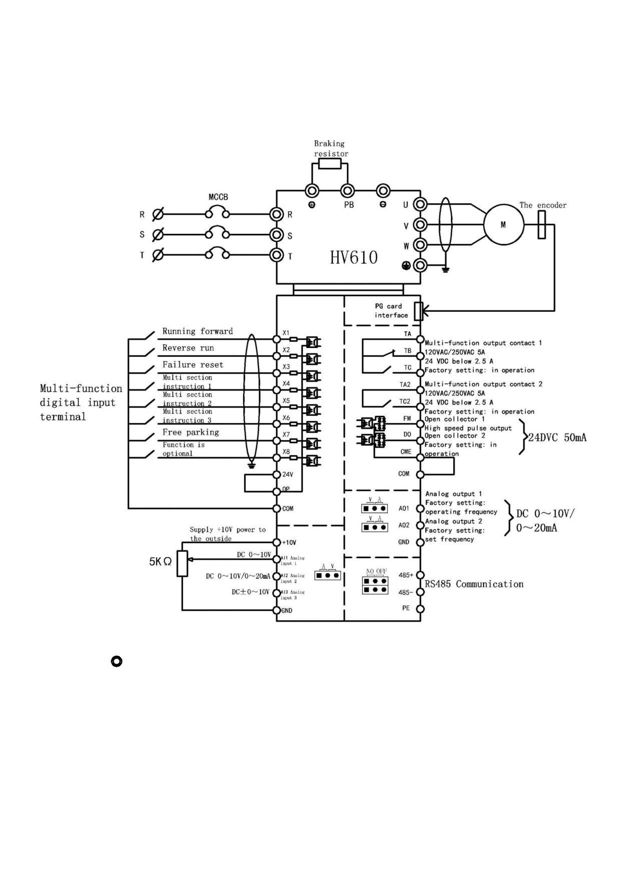
2.2.4 Standard wiring diagram of frequency inverter
Precautions:
1) Terminal
means main circuit terminal and O means control circuit terminal.
15
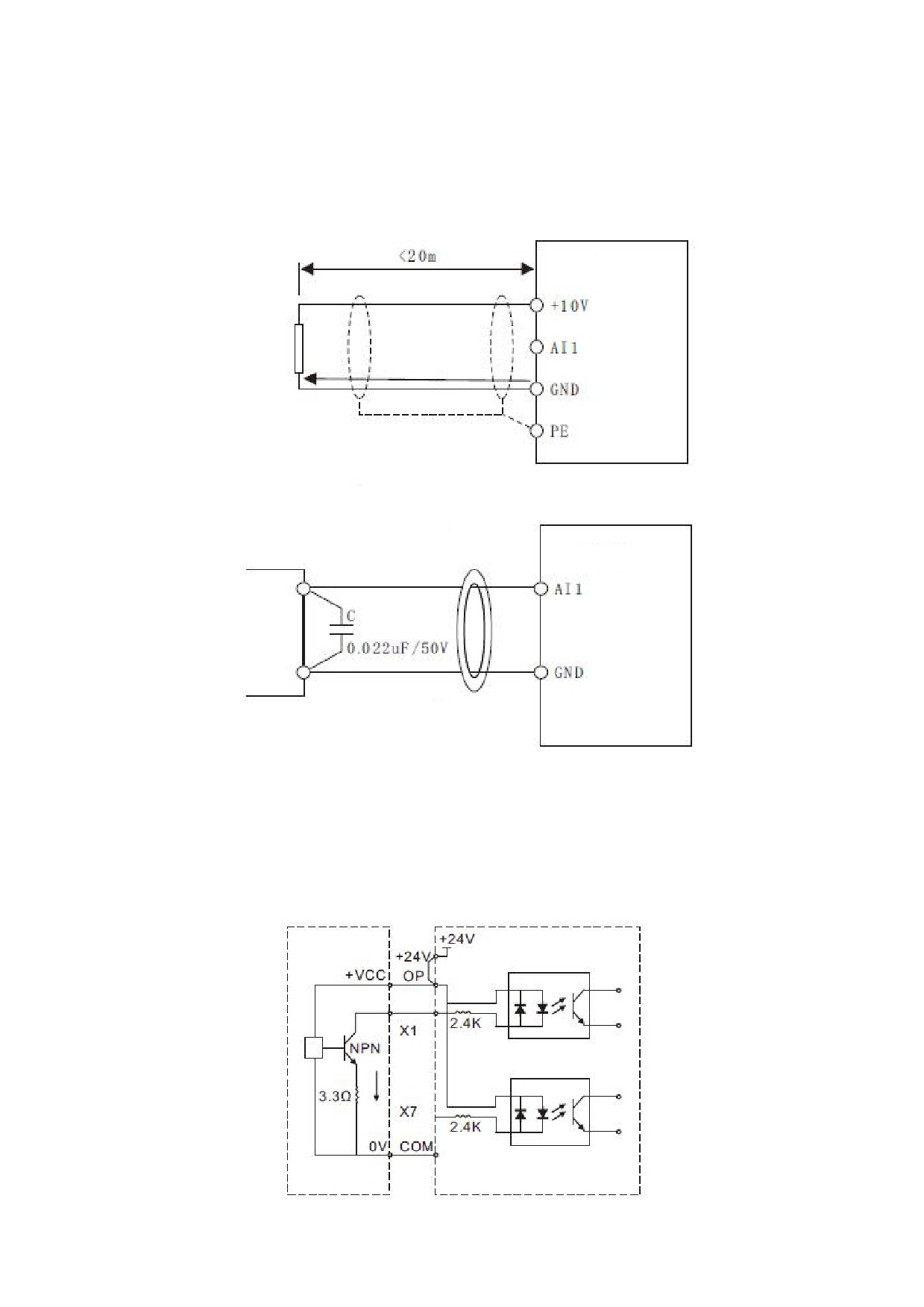
2.2.5 Control circuit wiring mode
a) Analog input terminal because weak analog voltage signals are particularly susceptible to external
interference, shielded cables are generally required, and the wiring distance should be as short as possible, not
exceeding 20m. As shown in the figure, when some analog signals are seriously disturbed, filter capacitors or ferrite
cores need to be added to the analog signal source side:
HV610
Potentiometer
Wiring diagram of analog input terminal
Pass through or in the same
direction 2 - 3 turn in the
same direction
HV610
Ferrite magnetic ring
Schematic diagram of processing and wiring for analog input terminals
b) Digital input terminal: Shielded cables are generally required, and the wiring distance should be as short as
possible, not exceeding 20m. When active driving mode is selected, necessary filtering measures should be taken
for crosstalk of power supply. It is recommended to use contact control square.
z
Leakage wiring
Signal
External controller
Frequency inverter control panel
Leakage (NPN) connection mode
16
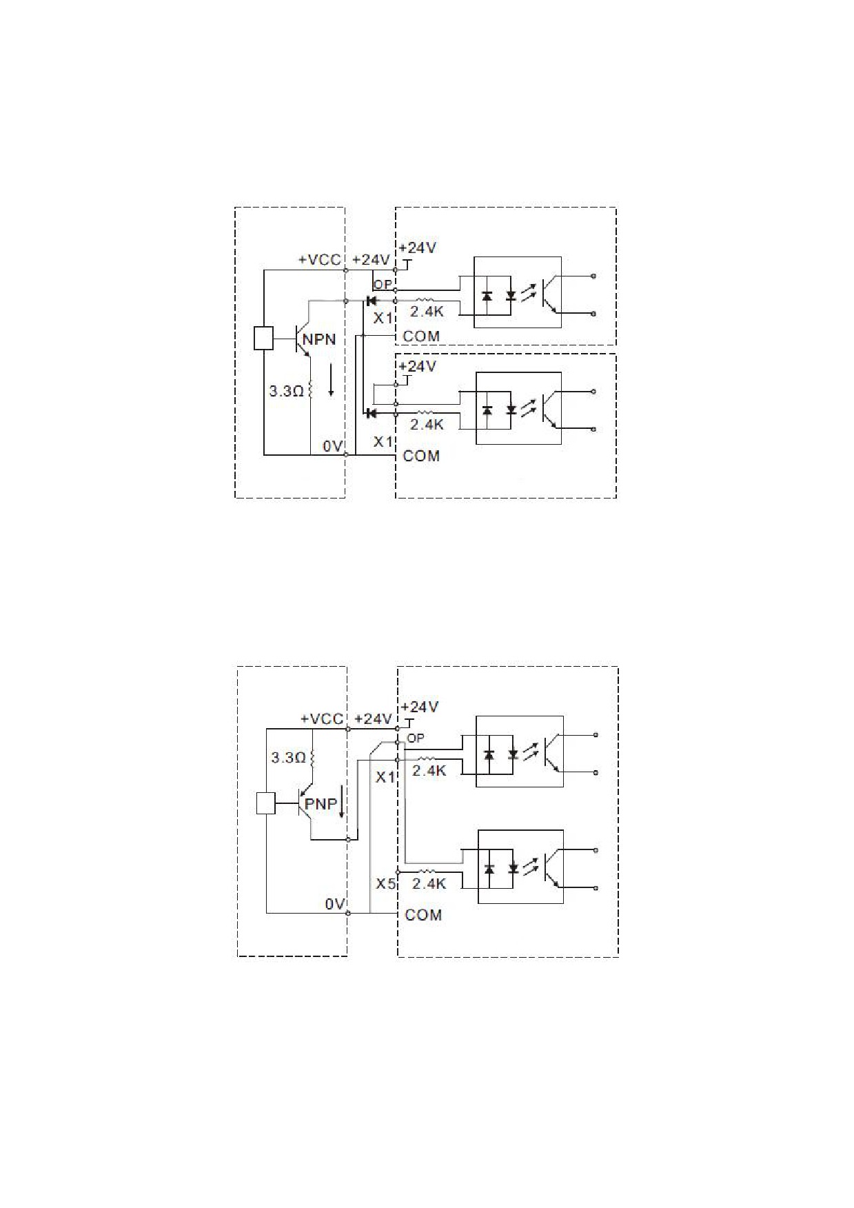
This is one of the most common wiring methods. If an external power supply is used, the short connector
between + 24V and OP and the short connector between COM and CME must be removed. The positive electrode of
the external power supply is connected to OP and the negative electrode of the external power supply is connected
to CME, and the external trigger signal is connected to the corresponding DI.
Frequency 1 inverter control panel
Signal
External controller
Frequency 2 inverter control panel
Multiple frequency inverters digital input and connection leakage type connection mode
Multiple frequency inverters digital input terminals cannot be connected and used, otherwise it may cause
incorrect operation of the input terminals. If it is needed that the input terminals of different frequency inverters are
connected in parallel, the diode is connected in series at the X terminal and the wiring is as shown above and the
diode needs to meet IF>10mA,UF<1V
Signal
External controller
Frequency inverter control panel
Source type (PNP) wiring mode
This wiring mode must remove the short connectors of +24v and OP, and connect +24v to the common terminal
of the external controller together, COM and OP are connected together at the same time. If an external power
supply is used, the short connector between COM and CME must also be removed,and the external trigger signal is
connected to the corresponding DI.
17
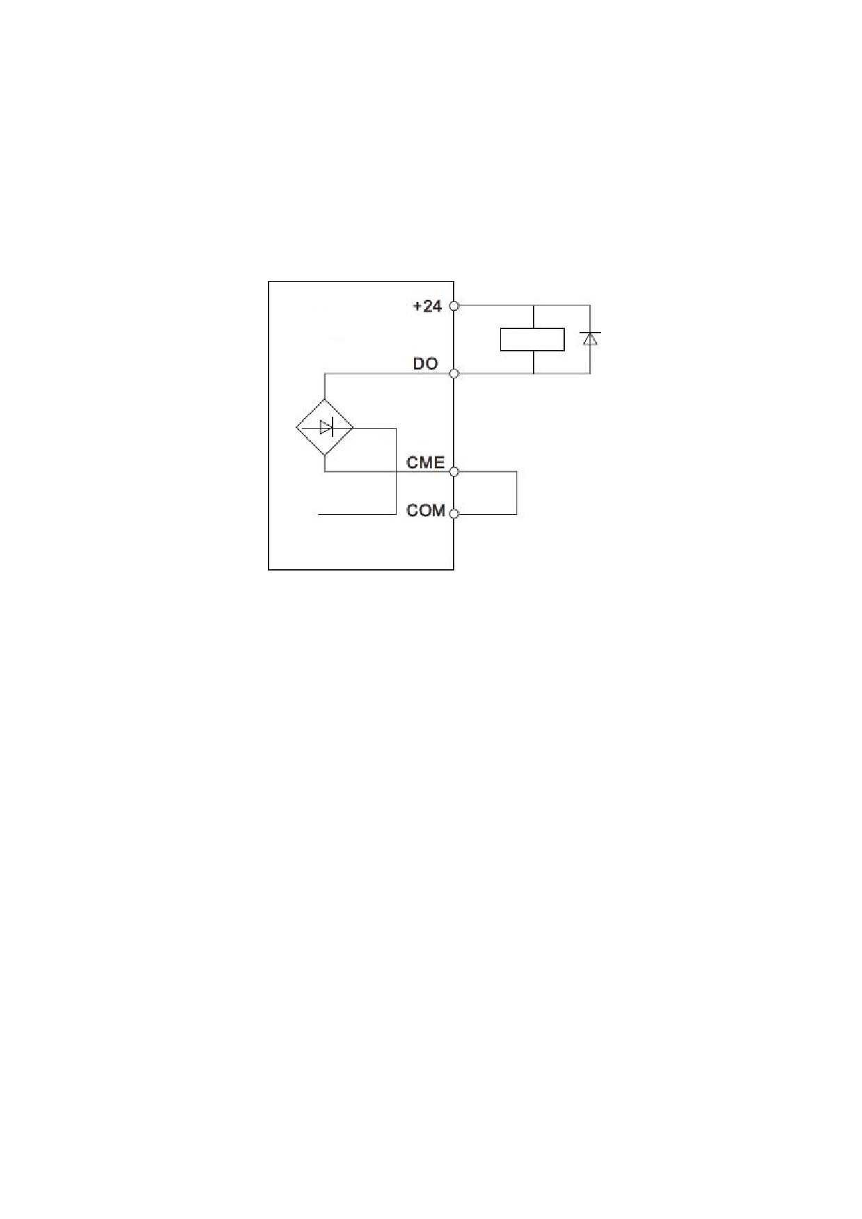
c) Digital output terminal: When the digital output terminal needs to drive the relay, absorption diodes should be
installed on both sides of the relay coil. Otherwise, it is easy to cause damage to the DC 24V power supply and the
driving capacity is not more than 50mA.
Note: as shown in the figure, the polarity of the absorption diode must be installed correctly. Otherwise,
when the digital output terminal has output, the DC 24V power supply will be burnt out immediately.
HV610
Relay
Diode
18
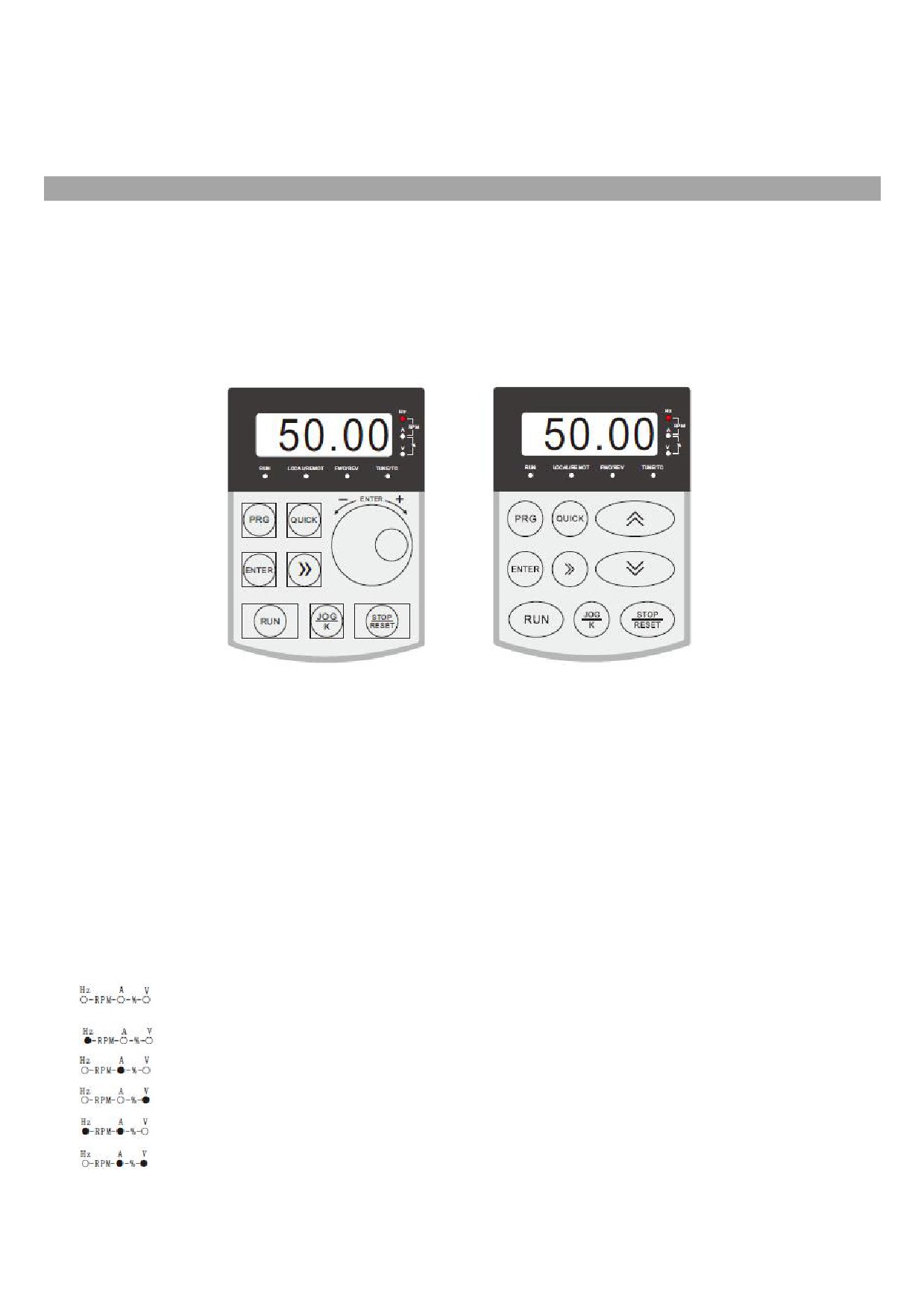
Chapter III Process operation
3.1 Operation keyboard and display interface
The operating keyboard of the series of frequency inverters can modify the functional parameters of the
frequency inverter, monitor the working state of the frequency inverter, and control the operation of the frequency
inverter (starting and stopping). Its appearance and functional area are shown in the following figure:
3.2
Indicator light indicates run
RUN: When the light is on, it indicates that the frequency inverter is in operation, and when the light is off, it
indicates that the frequency inverter is in shutdown state
LOCAL/REMOT: Keyboard operation, terminal operation and remote operation
(communication control)
indicator light
FWD/REV: Positive and negative rotation indicator light, which indicates that it is in reverse rotation when the
light is on
TUNE/TC: Tuning / torque control / fault indicator light, light on indicates torque control mode, light slow flashing
indicates tuning state, and light flash indicates fault state.
The unit indicator lamp is used to indicate the unit of the current display data (○ marks off, ●
marks on). There are the following units:
Hz frequency unit
A current unit
V voltage unit
RMP rotational speed unit
% percentage
Total of 5 - bit LED displays can display the set frequency, output frequency, various monitoring data and alarm
codes, etc.
19
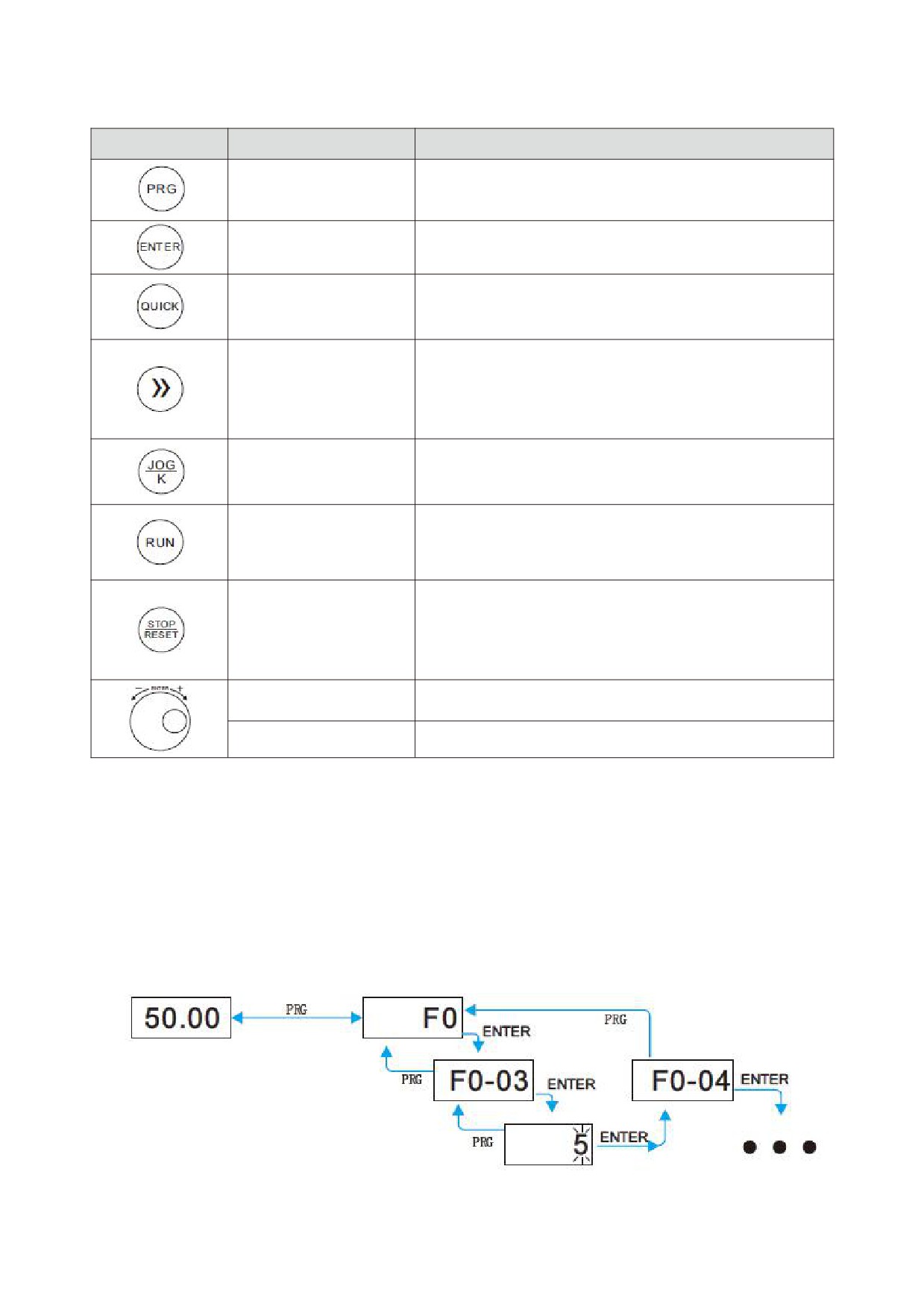
3.3
key function description
Key
Key name
Functionalities
Enter or exit the first-level menu and view the function
Menu key
sequence code
Enter the menu screen step by step and set parameters
Set key
for confirmation
Switch different menu modes according to F0 - 43
Menu mode select key
median value ( the default is a menu mode )
Under the shutdown display interface and the operation
display interface, the display parameters can be
Shift key
selected according to the loop. When modifying a
parameter, you can select the modification bit of the
Multifunction selection
According to F0 - 07, function switching can be defined
key
as command source or fast direction switching.
When it is set to keyboard control, forward rotation
Run key
operation instruction will be issued to start the
frequency inverter operation.
When running, pressing this key can be used to stop the
running operation. When the fault alarm is on, it can be
Stop / reset key
used to reset the operation. And the characteristics of
the key are restricted by the function code F0 - 08.
Increment key
Increment of data or function code
Descending key
Decrements of data or function code
3.4 Methods of checking and modifying function codes
The operation panel of this series of frequency inverters uses a three-level menu structure to set parameters
and other operations.
The three-level menus are: function parameter group (I - level menu) → function code (II - level menu) →
function code setting value (level III menu).
State parameter
Level I menu
When flashing, press // to modify
(Default screen)
(Function code group
number selection)
Toggle
Return
Enter
Level II menu
(Function code serial
Enter
number selection)
Return
Enter
Next function code
Level III menu
serial number
(Function code parameter
Give up
Save
value setting)
Description: press PRG key or enter key to return to the level II menu when operating the level II menu. The
difference between the two is: press enter to save the setting parameters and return to the secondary menu, and
20
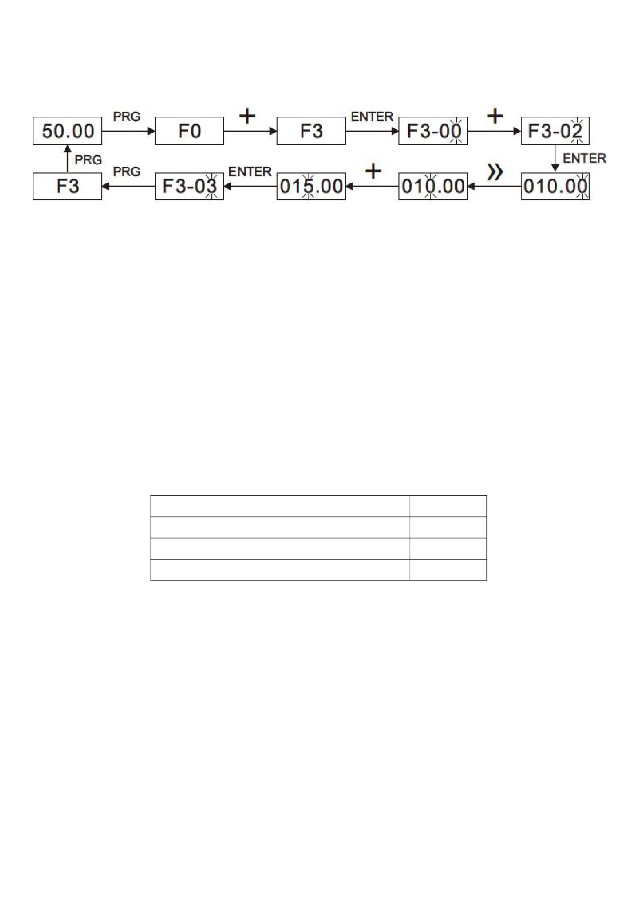
automatically transfer to the next function code; while pressing PRG key is to abandon the current parameter
modification and directly return to the secondary menu of the current function code serial number.
Example: example of setting function code F3 - 02 to 15.00 Hz from 10.00 Hz
In the level III menu state, if the parameter does not flash, it indicates that the function code cannot be modified.
Possible reasons are:
This function code is an unmodified parameter, such as frequency inverter type, actual detection parameter,
operation record parameter, etc.
This function code cannot be modified in the running state. It can only be modified after shutdown.
3.5 Two quick search modes for function code parameters there
Are many function codes in this series. In order to facilitate quick search by users, the frequency inverter also
provides two quick search methods for function codes:
1) Selecting and customizing common function codes and users, up to 30 of which can be customized, to form a
user-defined code function code set; the user determines the function parameters to be displayed through the FE
group
2) Automatically arranges the function codes different from the factory values and the frequency inverters for
quick selection by the user;
This provides three function code lookup methods, the display code of each parameter display method is:
Parameter display mode
Display
Function parameter mode
--F--
User - customized parameter method
--U-
The method for changing parameters by the users
--C-
The display modes of the three function codes are switched by the quick key on the panel ( F0 - 43 is set to 11 ),
and the search or modification method after entering the function codes of each group is the same as that of the
previous keyboard operation:
3.6 Commissioning
The series of frequency inverters has three operation control modes, which including keyboard control, terminal
control and RS - 485 control. Its control can be selected by setting the function code F0 - 02.
Through keyboard operation, the function code F0 - 02 = 0, i.e. the panel start-stop control mode, presses the
run key on the keyboard, and the frequency inverter starts to run ( the run indicator lights up ); When the frequency
inverter is running, press the stop key on the keyboard to stop the frequency inverter ( the run indicator goes out )
3.7 Motor characteristic parameter setting and self - learning
When the frequency inverter operates in the “vector control" (F0 - 01 = 0 or 1) mode, it is highly dependent on
accurate motor parameters. This is one of the important differences from the “VF control" (F0 - 01 = 2) mode. In order
21
for the frequency inverter to have good driving performance and operating efficiency, the frequency inverter must
obtain the preparation parameters of the controlled motor.
Motor 1 parameter
Parameter description
Description
Rated power / voltage / current / frequency / speed of
Model parameters, manual
F1-01 F1-05
motor
input
Equivalent stator resistance, inductance, rotor
F1-06 F1-20
Tuning parameter
inductance, etc. inside the motor
Methods for obtaining the internal electrical parameters of the controlled motor by the frequency inverter include
dynamic identification, static identification, manual input of motor parameters, etc.
Identification method
Application
Identification effect
Suitable for asynchronous motors. Occasions where the
No
- load dynamic
motor and the application system are conveniently
Best
identification
separated
On
- load dynamic
Suitable for asynchronous motors. Where the motor is
May
identification
not easily separated from the application system
It is only suitable for asynchronous motors, where it is
Static identification
difficult to separate the motor from the load and dynamic
Poor
identification of operation is not allowed
It is only suitable for asynchronous motors. When the
motor is difficult to separate from the application system,
Manually
enter
the parameters of the same type of electric machine
May
parameters
successfully identified by the frequency inverter are
copied and input into the corresponding function codes
of F1-00~F1-10
Automatic tuning of motor parameters (motor self - learning) steps are as follows:
The following explains the parameter identification method of the default motor
1 as an example. The
identification method of the motor 2 is the same as that of the default motor 1, except that the function code number
needs to be changed in a targeted way:
z
If the motor can be completely disconnected from the load, under the condition of power failure, the motor
can be mechanically separated from the load so that the motor can rotate freely without load.
z
After power on, first select the frequency inverter command source (F0 - 02) as the operation panel
command channel.
z
Accurately input the nameplate parameters of the motor (for example, F1-00 ~ F1-05). Please input the
parameters of the lower surface according to the actual parameters of the motor (according to the current
motor selection)
z
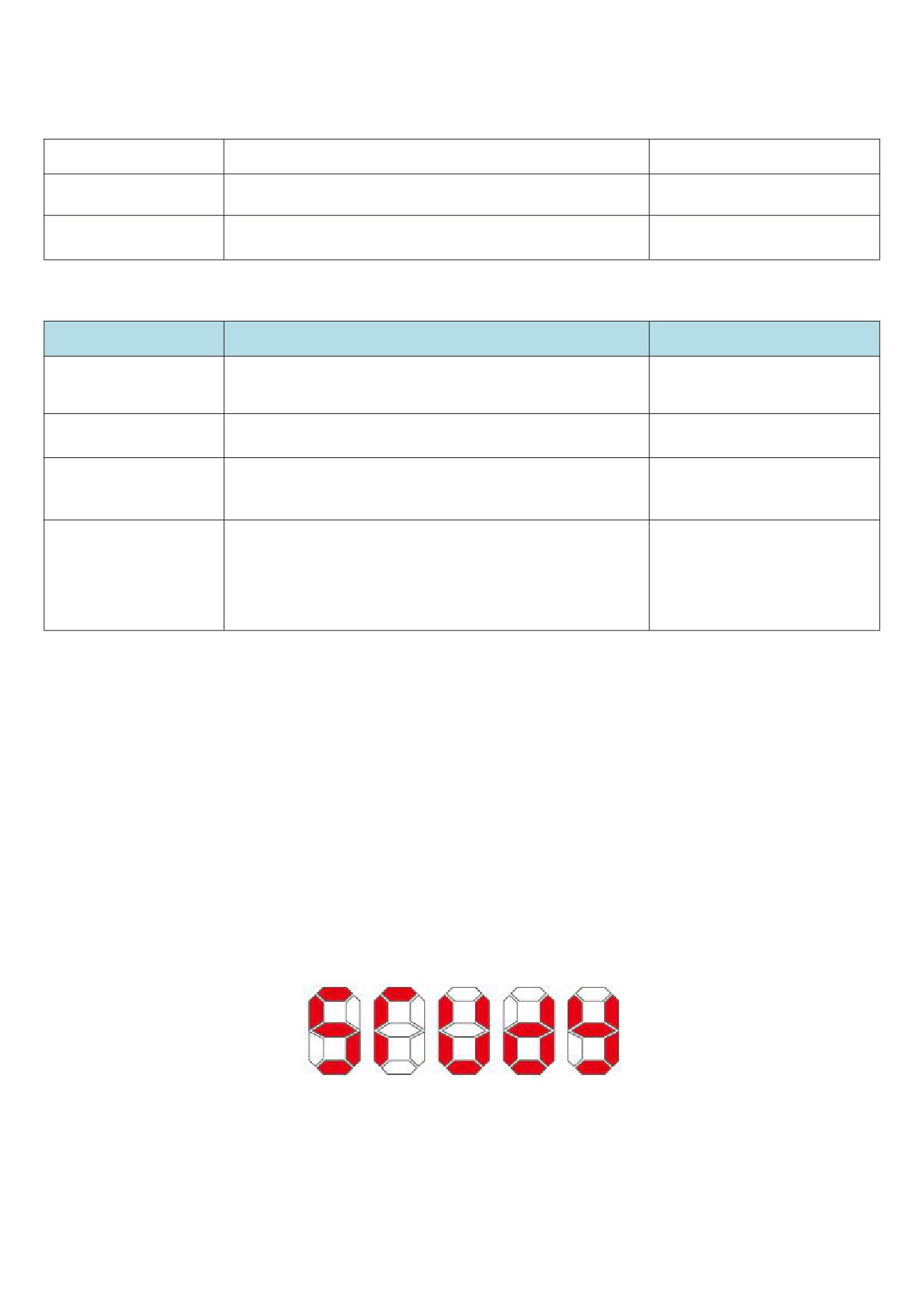
If it is an asynchronous motor, then F1 - 29 (tuning selection, for motor 2, it should be FB- 29 function code)
please select 2 (asynchronous motor fully tuned), press enter to confirm, at this point, the keyboard shows
STUDY, as shown in the following figure:
Then press the run key on the panel, the frequency inverter will drive the motor to accelerate and decelerate,
rotate forward and backward, the operation indicator light will illuminate, and the operation duration will be
recognized for about 2 minutes. When the above display information disappears, the normal parameter display state
will be returned, indicating that the tuning is completed. After the complete tuning, the frequency inverter will
automatically calculate the following parameters of the motor:
F1 - 06: Asynchronous motor stator resistance
F1 - 07: Asynchronous motor rotor resistance
22
F1 - 08: Induction motor leakage inductance
F1 - 09: Induction motor mutual inductance resistance
F1 - 10: Asynchronous motor no-load current
If the motor cannot be completely disconnected from the load, F1 - 29 (motor 2 is FB - 29) please select 1
(asynchronous motor is still tuned), and then press the run key on the panel to start the motor parameter
identification operation.
23

Chapter IV Functional parameters
F0 - 46 is set to a value other than 0, i.e. the parameter protection password is set. In the function parameter mode
and the user change parameter mode, the parameter menu cannot be entered until the password is correctly entered.
To cancel the password, F0 - 46 needs to be set to 0.
Group F and group P are basic functional parameters, and group U is monitoring functional parameters.
4.1 Summary of basic functional parameters
Function
Factory
Communica
Name
Setting range
code
value
tion address
F0 group basic functions
Bits: monitoring group U0
0: Not displayed
1: Display
F0-00
Menu mode selection
11
F000H
Ten digits: special parameter group P
0: Not displayed
1: Display
0: No PG open loop vector control
F0-01
Control operation mode
1: PG closed loop vector control
2
F001H
2: V/F control
0: Operation panel
Run command channel
F0-02
1: Terminals
0
F002H
selection
2: Communication
0: Number setting 1
1: Number setting 2
2: AI1
3: AI2
Main frequency source X
4: AI3
F0-03
1
F003H
selection
5: X5 pulse given
6: Multi-segment instruction
7: Simple PLC
8: PID
9: Communication given
0: Allowed
F0-04
Anti - reverse selection
1: Forbidden (0 frequency operation when
0
F004H
reverse command is applied)
0: Standard
Phase sequence
F0-05
1: Carry out phase sequence exchange.
0
F005H
selection
(rotation direction changes)
0: Allowed (when the power supply is turned on
and there is an operation command, the
Operation selection
operation will start.)
F0-06
0
F006H
when power is on
1: Prohibit (even if there is an operation
command while the power supply is on, the
motor selection is also prohibited.)
0: JOG.K is invalid
1: Operation panel command channel and
remote command channel ( terminal command
JOG.K key function
channel or communication command channel )
F0-07
0
F007H
selection
switch
2: Forward and reverse switching
3: JOG forward
4: Reverse JOG
24

Function
Factory
Communica
Name
Setting range
code
value
tion address
0: STOP / RES key stop function is valid only in
STOP/RESET key
keyboard operation mode
F0-08
1
F008H
function
1: STOP / RES key stop function is valid in any
operation mode
F0-09
Preset frequency
0.00Hz ~ maximum frequency ( F0
-
16
)
50.00Hz
F009H
0.00s~650.00s(F0-12=2)
Model
F0-10
Acceleration time 1
0.0s~6500.0s(F0-12=1)
determin
F00AH
0s~65000s(F0-12=0)
ation
0.00s~650.00s(F0-12=2)
Model
F0-11
Deceleration time 1
0.0s~6500.0s(F0-12=1)
determin
F00BH
0s~65000s(F0-12=0)
ation
0: 1 second
Acceleration /
F0-12
1: 0.1 second
1
F00CH
deceleration time unit
2: 0.01 second
Acceleration and
0: maximum frequency ( F0 - 12
)
F0-13
deceleration time
1: set frequency
0
F00DH
reference frequency
2: 100Hz
0: slow down and stop
F0-14
Shutdown mode
0
F00EH
1: free parking
F0-15
Droop control
0.00Hz~10.00Hz
0.00Hz
F00FH
50.00Hz~500.00Hz(F0-25=2)
F0-16
Maximum frequency
50.00Hz
F010H
50.0Hz~3200.0Hz(F0-25=1)
0: F0 - 18 settings
1: AI1
2: AI2
F0-17
Upper frequency source
0
F011H
3: AI3
4: X5 pulse setting
5: Communication given
Lower frequency F0 - 20 ~ maximum frequency
F0-18
Upper limiting frequency
50.00Hz
F012H
F0 - 16
F0-19
Upper frequency offset
0.00Hz ~ maximum frequency F0 - 16
0.00Hz
F013H
F0-20
Lower limit frequency
0.00Hz ~ upper frequency F0 - 18
0.00Hz
F014H
Operating mode with set
0: The following limited frequency operation
F0-21
frequency lower than
1: Shutdown
0
F015H
lower limit frequency
2: Zero speed operation
Model
F0-22
Carrier frequency
0.5kHz~16.0kHz
determin
F016H
ation
Carrier frequency adjusts
0: No
F0-23
1
F017H
with load
1: Yes
LED shutdown operation
0: Shutdown operation display separated
F0-24
0
F018H
display selection
1: Stop operation display does not separate
1: One decimal point
F0-25
Frequency decimal point
2
F019H
2: Two decimal points
Digital setting frequency
0: No memory
F0-26
shutdown memory
1
F01AH
1: Memory
selection
25
Function
Factory
Communica
Name
Setting range
code
value
tion address
Runtime frequency
0: Operating frequency
F0-27
command UP / DOWN
1
F01BH
1: Set frequency
reference
0: Motor 1
F0-28
Motor selection
0
F01CH
1: Motor 2
Auxiliary frequency
F0-29
Same as F0 - 03 ( main frequency source X )
0
F01DH
source Y
Base value of auxiliary
0: Relative to maximum frequency
F0-30
frequency Y range during
0
F01EH
1: Relative to frequency source x
superposition
Auxiliary frequency Y
F0-31
range during
0% - 150%
100%
F01FH
superposition
Bits: frequency selection
0: Main frequency x
1: Main and auxiliary operation results ( the
operation relationship is defined by ten - digit
confirmation )
2: Switch between main frequency X and
auxiliary frequency Y.
3: Switching between main frequency X and
main and auxiliary operation results
F0-32
Frequency superposition
00
F020H
4. The auxiliary frequency Y is cut OFF from the
result of the main and auxiliary operations
change
10 Bits: frequency primary and secondary
operation relation
0: Primary + secondary
1: Primary and secondary
2: Maximum value of both
3: Minimum of both
Auxiliary frequency
F0-33
source offset frequency
0.00Hz ~ maximum frequency F0 - 16
0.00Hz
F021H
during superposition
Bits: operation panel command binding
frequency source selection
0: Unbound
1: Number setting
2: AI1
3: AI2
4: AI3
Command source
5: X5 pulse quantity setting
F0-34
bundling frequency
0000
F022H
6: Multi-segment instruction
source
7: Simple PLC
8: PID
9: Communication given
Ten bits: terminal command binding frequency
source selection
Hundred bits: communication command binding
frequency source selection
0: Fan running when running
F0-35
Cooling fan control
0
F023H
1: The fan is running all the time
Forward and reverse
F0-36
0.0s~3000.0s
0.0s
F024H
dead time
0000~FFFF
Tens
Ones
Parameter 1 displayed at
Operating frequency
F0-37
H401F
F025H
run time
Setting frequency
Bus bar voltage
Output voltage
Output current
Output power
Output torque
X output state
26
//////////////////////