HSD7-E Series AC Servo Drive. User's Manual (Version: V0.1) - page 6
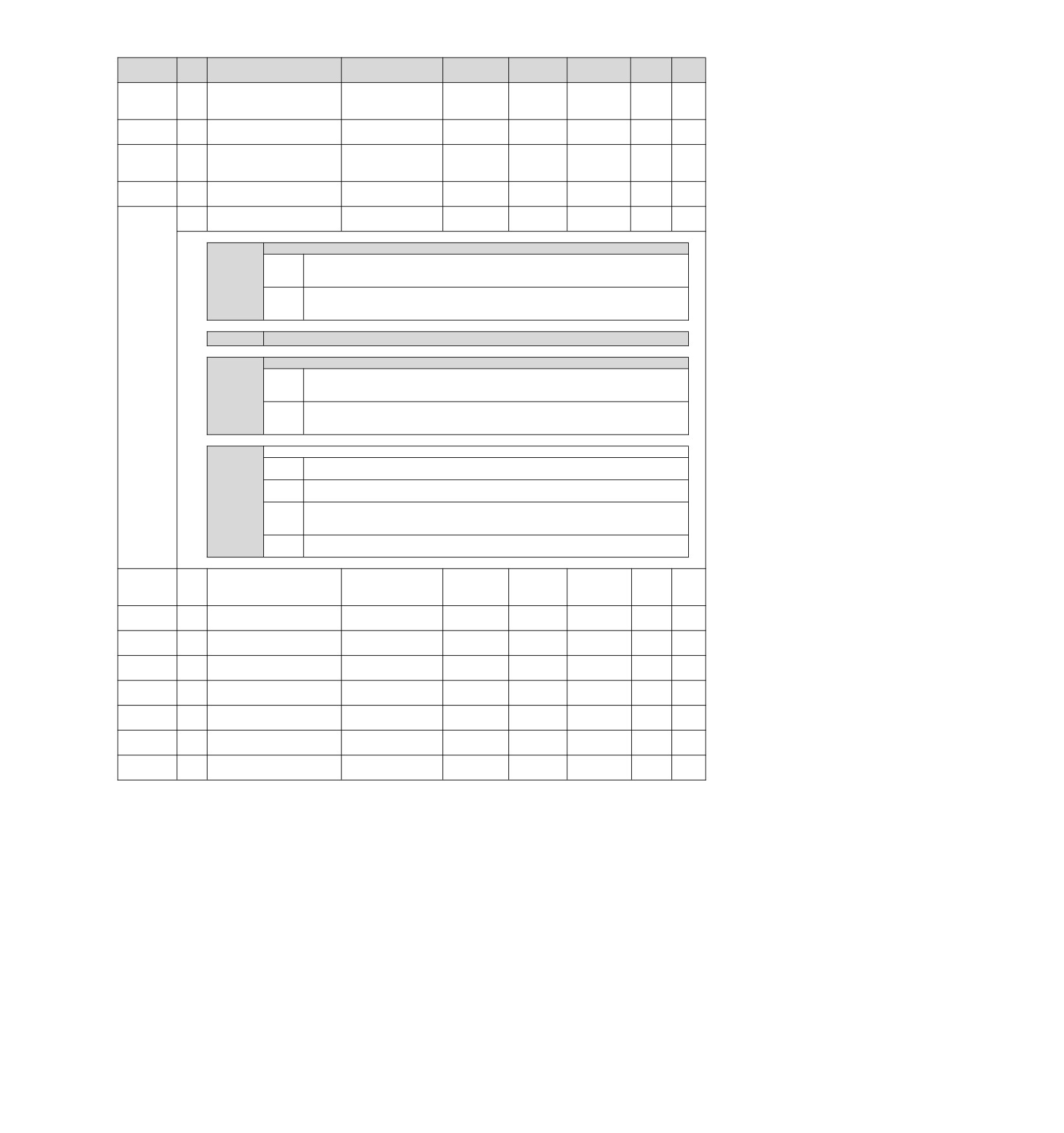
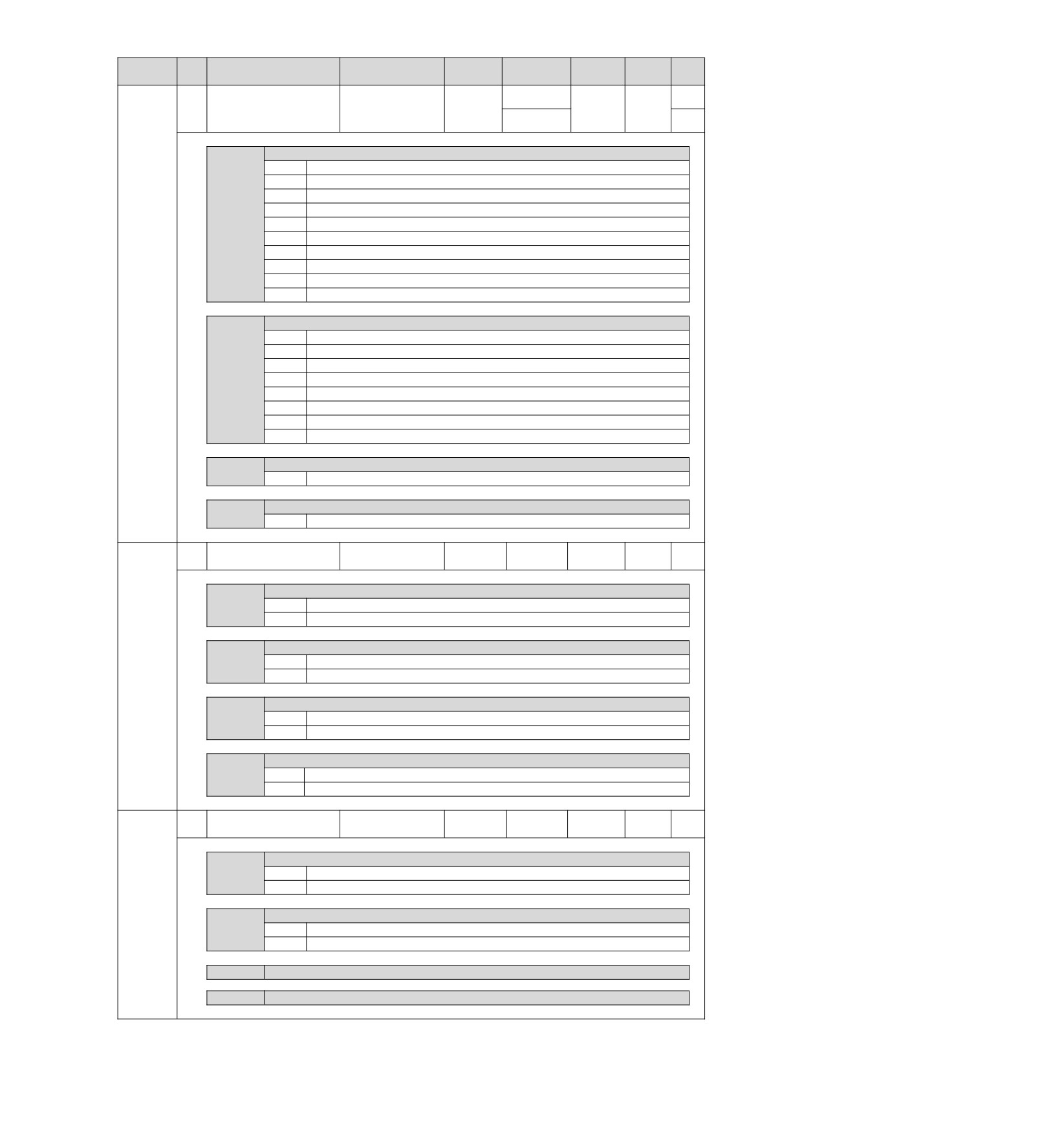
Factory
Available
Catego
Pn No.
Size
Name
Setting range
Setting Unit
Model
setting
time
ry
When main loop voltage
Effective
Pn425
2
drops
0~1000
1 ms
100
Setup
immediately
Torque limit release time
Torque feedforward moving
Effective
Pn426
2
0~5100
0.1 ms
0
Setup
average time
immediately
Velocity
fluctuation
Effective
Adjust
Pn427
2
compensation
effective
0~10000
1 min-1
0
immediately
ment
velocity
Scan torque command
Effective
Adjust
Pn456
2
0~800
1%
15
amplitude
immediately
ment
Notch filter adjustment
Effective
Adjust
2
0000~0101
-
0101
switch 1
immediately
ment
n.X
Notch filter adjustment option 1
In the process of performing automatic adjustment
(without upper command),
0
automatic adjustment (with upper command) and custom adjustment, the notch filter
of the 1st stage will not be adjusted automatically.
In the process of performing automatic adjustment
(without upper command),
1
automatic adjustment (with upper command) and custom adjustment, the notch filter
of the 1st stage is automatically adjusted.
n.X
Appointment parameters (do not change it)
n.X
Notch filter adjustment option 2
In the process of performing automatic adjustment
(without upper command),
Pn460
0
automatic adjustment (with upper command) and custom adjustment, the notch filter
of the 2nd stage is automatically adjusted.
In the process of performing automatic adjustment
(without upper command),
1
automatic adjustment (with upper command) and custom adjustment, the notch filter
of the 2nd stage is automatically adjusted.
n.X
Notch filter adjustment option 3
When the adjustment-free is invalid (manual gain), the notch filters of the 1st and 2nd
0
segments will not be automatically adjusted.
When no adjustment is effective (manual gain), the notch filters of the 1st and 2nd
1
segments are automatically adjusted. (suitable for belt mechanism)
When no adjustment is effective (manual gain), the notch filters of the 1st and 2nd
2
segments are automatically adjusted. (Suitable for ball screw mechanism or linear
servo motor)
When no adjustment is effective (manual gain), the notch filters of the 1st and 2nd
3
segments are automatically adjusted. (Rigid Body System)
Velocity
fluctuation
Effective
Adjust
Pn49F
2
compensation
effective
0~10000
1 mm/s
0
immediately
ment
velocity
Effective
Pn501
2
Zero position fixing value
0~10000
1 min-1
10
Setup
immediately
Effective
Pn502
2
Rotation detection value
1~10000
1 min-1
20
Setup
immediately
Speed consistent signal
Effective
Pn503
2
0~100
1 min-1
10
Setup
output range
immediately
Brake command-
Effective
Pn506
2
0~50
10 ms
0
Setup
Servo OFF delay time
immediately
Brake command output
Effective
Pn507
2
0~10000
1 min-1
100
Setup
speed value
immediately
Servo OFF-
Effective
Pn508
2
10~100
1 min-1
50
Setup
Brake Command Wait Time
immediately
Effective
Pn509
2
Instant stop hold time
20~50000
10 ms
20
Setup
immediately
95
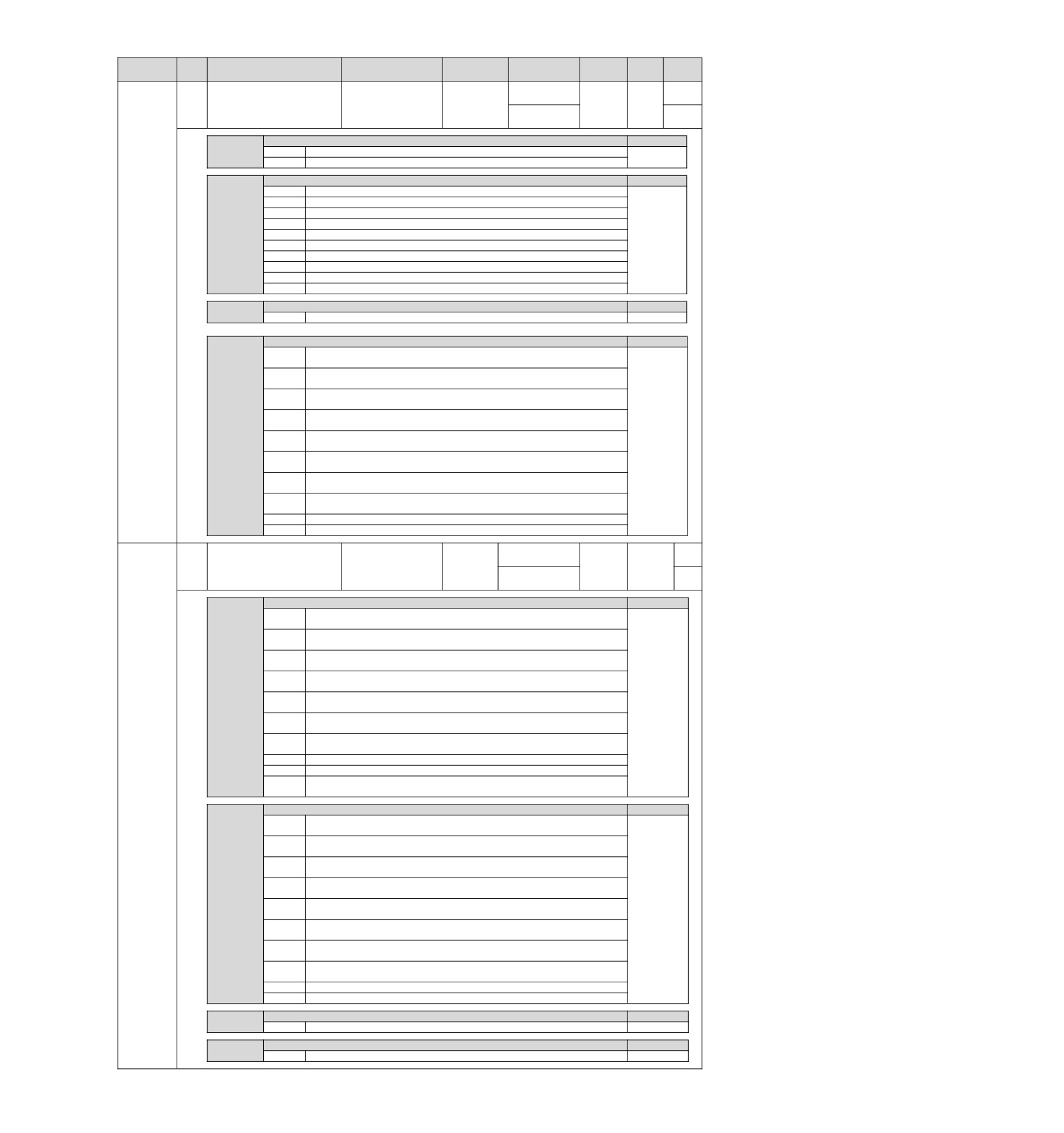
Factory
Available
Categ
Pn No.
Size
Name
Setting range
Setting Unit
Model
setting
time
ory
1801
(axis A)
P
5841
(axis b)
Power
2
Input signal selection 1
0000~9991
-
Setup
0801 (axis A)
restart
B
0841 (axis b)
n.X
Allocation mode of input signals
Remarks
0
Appointment Parameters (Do Not Set)
1
According to different signals.
n.X
Allocation of servo ON input (/S-ON) signal
Remarks
0
CN1-IN0 takes effect when the input signal is ON.
1
CN1-IN1 takes effect when the input signal is ON.
2
CN1-IN2 takes effect when the input signal is ON.
3
CN1-IN3 takes effect when the input signal is ON.
4
CN1-IN4 takes effect when the input signal is ON.
5
CN1-IN5 takes effect when the input signal is ON.
6
CN1-IN6 takes effect when the input signal is ON.
7
CN1-IN7 takes effect when the input signal is ON.
8
Fixed the signal as "invalid" all the time.
9
Set the signal to "active" at all times.
n.X
P action command input (/P-CON) signal distribution
Remarks
Pn50A
0~9
Same distribution as servo on input (/S-ON) signal.
n.X
Prohibit forward rotation side drive input (P-OT) signal allocation
Remarks
When the input signal of CN1-IN0 is ON (closed), forward rotation side
0
drive can be performed.
When the input signal of CN1-IN1 is ON (closed), forward rotation side
1
drive can be performed.
When the input signal of CN1-IN2 is ON (closed), forward rotation side
2
drive can be performed.
When the input signal of CN1-IN3 is ON (closed), forward rotation side
3
drive can be performed.
When the input signal of CN1-IN4 is ON (closed), forward rotation side
4
drive can be performed.
When the input signal of CN1-IN5 is ON (closed), forward rotation side
5
drive can be performed.
When the input signal of CN1-IN6 is ON (closed), forward rotation side
6
drive can be performed.
When the input signal of CN1-IN7 is ON (closed), forward rotation side
7
drive can be performed.
8
The signal is always fixed as "forward rotation side drivable".
9
The signal is always fixed as "No Forward Turn Side Drive".
8832
(axis A)
P
8876
(axis b)
Power
2
Input signal selection 2
0000~9999
-
Setup
8881
(axis A)
restart
B
8885
(axis b)
n.X
Prohibit reverse rotation side drive input (P-OT) signal allocation
Remarks
When the input signal of CN1-IN0 is ON (closed), reverse rotation side
0
drive can be performed.
When the input signal of CN1-IN1 is ON (closed), reverse rotation side
1
drive can be performed.
When the input signal of CN1-IN2 is ON (closed), reverse rotation side
2
drive can be performed.
When the input signal of CN1-IN3 is ON (closed), reverse rotation side
3
drive can be performed.
When the input signal of CN1-IN4 is ON (closed), reverse rotation side
4
drive can be performed.
When the input signal of CN1-IN5 is ON (closed), reverse rotation side
5
drive can be performed.
When the input signal of CN1-IN6 is ON (closed), reverse rotation side
6
drive can be performed.
7
The signal is always fixed as "No reversal Turn Side Drive".
8
The signal is always fixed as "reverse rotation side drivable".
When the input signal of CN1-IN0 is OFF (cut off), reverse rotation side
9
drive can be performed.
Pn50B
n.X
Assignment of Alarm Reset Input (/ALM-RST) Signal
Remarks
The input signal of CN1-IN0 is valid from the edge of OFF(cut off) to
0
ON(closed).
The input signal of CN1-IN1 is valid from the edge of OFF(cut off) to
1
ON(closed).
The input signal of CN1-IN2 is valid from the edge of OFF(cut off) to
2
ON(closed).
The input signal of CN1-IN3 is valid from the edge of OFF(cut off) to
3
ON(closed).
The input signal of CN1-IN4 is valid from the edge of OFF(cut off) to
4
ON(closed).
The input signal of CN1-IN5 is valid from the edge of OFF(cut off) to
5
ON(closed).
The input signal of CN1-IN6 is valid from the edge of OFF(cut off) to
6
ON(closed).
The input signal of CN1-IN7 is valid from the edge of OFF(cut off) to
7
ON(closed).
8
Fixed the signal as "invalid" all the time.
9
Appointment Parameters (Do Not Set)
n.X
Distribution of external torque limit input(/P-CL) signal on forward rotation side)
Remarks
0~9
Same distribution as servo on input (/S-ON) signal.
n.X
Distribution of external torque limit input(/P-CL) signal on reverse rotation side)
Remarks
0~9
Same distribution as servo on input (/S-ON) signal.
96
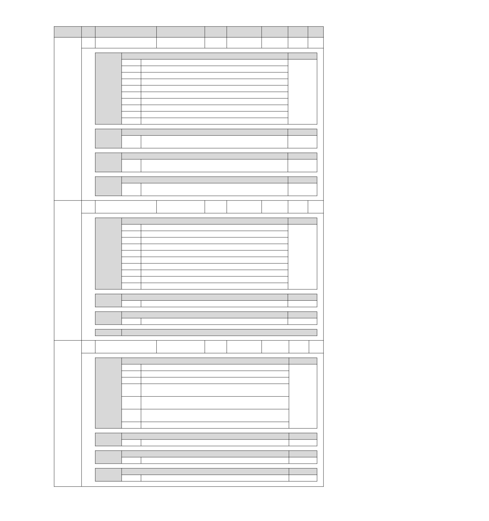
Setting
Available
Categor
Rema
Pn No.
Size
Name
Setting range
Factory setting
Unit
time
y
rks
Power
2
Input signal selection 3
0000~9999
-
8888
Setup
-
restart
n.X
Distribution of motor rotation direction switching input (/SPD-D) signal
Remarks
0
CN1-IN0 takes effect when the input signal is ON.
1
CN1-IN1 takes effect when the input signal is ON.
2
CN1-IN2 takes effect when the input signal is ON.
3
CN1-IN3 takes effect when the input signal is ON.
4
CN1-IN4 takes effect when the input signal is ON.
5
CN1-IN5 takes effect when the input signal is ON.
6
CN1-IN6 takes effect when the input signal is ON.
7
CN1-IN7 takes effect when the input signal is ON.
8
Fixed the signal as "invalid" all the time.
Pn50C
9
Set the signal to "active" at all times.
n.X
Internal setting speed switching input (/SPD-A) signal distribution
Remarks
The distribution of signals is the same as that of motor rotation
0~9
direction switching input (/SPD-D).
n.X
Rotation detection output(/TGON) signal distribution
Remarks
The distribution of signals is the same as that of motor rotation
0~9
direction switching input (/SPD-D).
n.X
The control mode switches the distribution of input (/C-SEL) signals
Remarks
The distribution of signals is the same as that of motor rotation direction
0~9
switching input (/SPD-D).
Power
2
Input signal selection 4
0000~0999
-
0888
Setup
-
restart
n.X
Zero position fixing input signals
Remarks
0
CN1-IN0 takes effect when the input signal is ON.
1
CN1-IN1 takes effect when the input signal is ON.
2
CN1-IN2 takes effect when the input signal is ON.
3
CN1-IN3 takes effect when the input signal is ON.
4
CN1-IN4 takes effect when the input signal is ON.
5
CN1-IN5 takes effect when the input signal is ON.
6
CN1-IN6 takes effect when the input signal is ON.
Pn50D
7
CN1-IN7 takes effect when the input signal is ON.
8
Fixed the signal as "invalid" all the time.
9
Set the signal to "active" at all times.
n.X
The command pulse prohibits the distribution of the input (/INHIBIT) signal
Remarks
0~9
Same distribution as zero position fixing input signals
n.X
Distribution of gain switching input(/ G-SEL) signals
Remarks
0~9
Same distribution as zero position fixing input signals
n.X
Appointment parameters (do not change it)
6611
(axis A)
Power
2
Output signal selection 1
0000~6666
-
Setup
-
6644
(axis b)
restart
n.X
Positing complete output(/COIN) signal distribution
Remarks
0
The above signals are output from CN1-OUT0 (7, 8) output terminals.
1
The above signals are output from CN1-OUT1 (9, 10) output terminals.
2
The above signals are output from CN1-OUT2 (11, 12) output terminals.
The above signals are output from CN1-OUT3 (32, 33) output
3
terminals.
The above signals are output from CN1-OUT4 (34, 35) output
4
terminals.
Pn50E
The above signals are output from CN1-OUT5 (36, 37) output
5
terminals.
6
Invalid (not using the above signal output).
n.X
Distribution of speed consistent output (/V-CMP) signal
Remarks
0~6
Same as positing complete output(/COIN) signal distribution
n.X
Rotation detection output(/TGON) signal distribution
Remarks
0~6
Same as positing complete output(/COIN) signal distribution
n.X
Distribution of servo ready output (/S-RDY) signal
Remarks
0~6
Same as positing complete output(/COIN) signal distribution
97
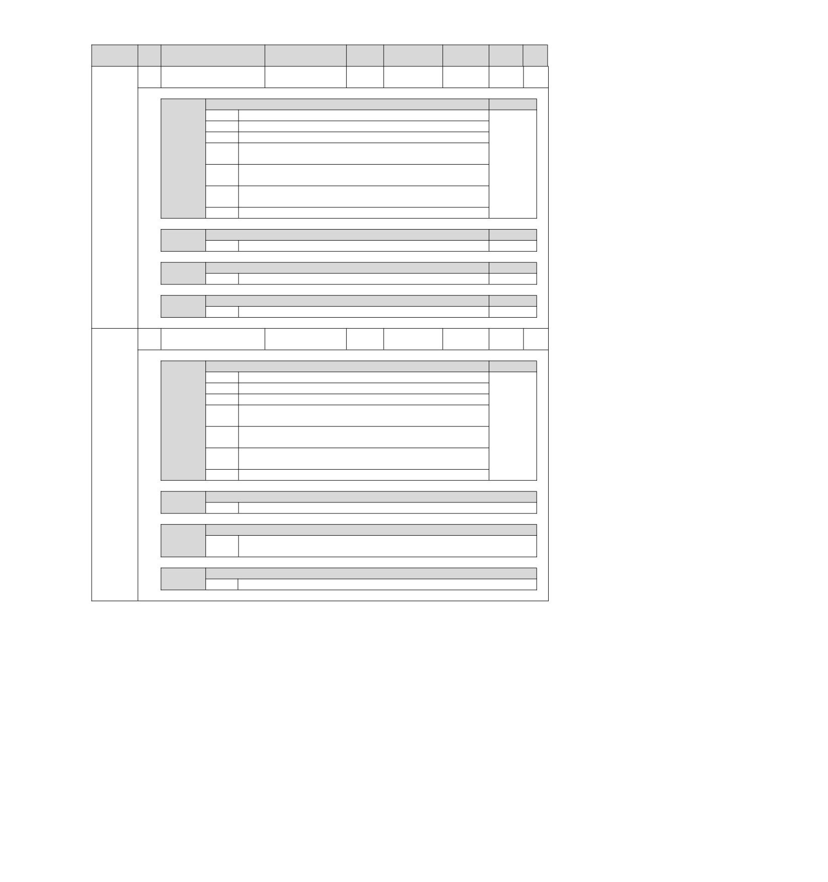
Setting
Available
Categor
Rem
Pn No.
Size
Name
Setting range
Factory setting
Unit
time
y
arks
6611
(axis A)
Power
2
Output signal selection 2
0000~6666
-
Setup
-
6644
(axis b)
restart
n.X
Distribution of torque limit detection output (/CLT) signal
Remarks
0
The above signals are output from CN1-OUT0 (7, 8) output terminals.
1
The above signals are output from CN1-OUT1 (9, 10) output terminals.
2
The above signals are output from CN1-OUT2 (11, 12) output terminals.
The above signals are output from CN1-OUT3 (32, 33) output
3
terminals.
The above signals are output from CN1-OUT4 (34, 35) output
4
terminals.
The above signals are output from CN1-OUT5 (36, 37) output
Pn50F
5
terminals.
6
Invalid (not using the above signal output).
n.X
Distribution of speed limit detection output (/VLT) signal
Remarks
0~6
Same as distribution of torque limit detection output (/CLT) signal
n.X
Distribution of brake control output (/BK) signal
Remarks
0~6
Same as distribution of torque limit detection output (/CLT) signal
n.X
Distribution of warning output (/WARN) signal
Remarks
0~6
Same as distribution of torque limit detection output (/CLT) signal
0666 (axis A)
Power
2
Output signal selection 3
0000~6666
-
Setup
-
3666
(axis b)
restart
n.X
Distribution of position nearby output (/NEAR) signal
Remarks
0
The above signals are output from CN1-OUT0 (7, 8) output terminals.
1
The above signals are output from CN1-OUT1 (9, 10) output terminals.
2
The above signals are output from CN1-OUT2 (11, 12) output terminals.
The above signals are output from CN1-OUT3 (32, 33) output
3
terminals.
The above signals are output from CN1-OUT4 (34, 35) output
4
terminals.
The above signals are output from CN1-OUT5 (36, 37) output
5
Pn510
terminals.
6
Invalid (not using the above signal output).
n.X
Distribution of output (/PGC) signal by encoder C pulse
0~6
Same as distribution of torque limit detection output (/CLT) signal
n.X
Distribution of command pulse input multiplication switching output (/PSELA) Signal
Same as distribution of position nearby output(/NEAR) signal the normal power
0~6
supply OFF
n.X
Distribution of Alarm output (ALM) signal
0~6
Same as distribution of torque limit detection output (/CLT) signal
98
Setting
Factory
Available
Categor
Pn No.
Size
Name
Setting range
Model
Unit
setting
time
y
8888
P
Power
2
Input signal selection 4
0000~9999
-
Setup
8836
(axis A)
restart
B
8872
(axis b)
n.X
Distribution of input (/DEC) signal of origin reset deceleration switch
0
CN1-IN0 takes effect when the input signal is ON.
1
CN1-IN1 takes effect when the input signal is ON.
2
CN1-IN2 takes effect when the input signal is ON.
3
CN1-IN3 takes effect when the input signal is ON.
4
CN1-IN4 takes effect when the input signal is ON.
5
CN1-IN5 takes effect when the input signal is ON.
6
CN1-IN6 takes effect when the input signal is ON.
7
CN1-IN7 takes effect when the input signal is ON.
8
Fixed the signal as "invalid" all the time.
9
Set the signal to "active" at all times.
Pn511
n.X
Distribution of external latch input 1 (/EXT1) signal
0~4
Fixed the signal as "invalid" all the time.
5
CN1-IN5 takes effect when the input signal is ON.
6
CN1-IN6 takes effect when the input signal is ON.
7
CN1-IN7 takes effect when the input signal is ON.
8~C
Fixed the signal as "invalid" all the time.
D
CN1-IN5 is valid when the input signal is OFF(cut off).
E
CN1-IN6 is valid when the input signal is OFF(cut off).
F
CN1-IN7 is valid when the input signal is OFF(cut off).
n.X
Distribution of external latch input 2 (/EXT2) signal
0~F
Same distribution as external latch input 1(/EXT1) signal.
n.X
Distribution of external latch input 3 (/EXT3) signal
0~F
Same distribution as external latch input 1(/EXT1) signal.
Output
signal inversion
Power
2
0000~1111
-
0000
Setup
-
setting 0
restart
n.X
CN1-OUT0 (7, 8) terminal output signal inversion
0
Not reverse signal.
1
Reverses the signal.
n.X
CN1-OUT1 (9, 10) terminal output signal inversion
0
Not reverse signal.
Pn512
1
Reverses the signal.
n.X
CN1-OUT2 (11, 12) terminal output signal inversion
0
Not reverse signal.
1
Reverses the signal.
n.X
CN1-OUT3 (32, 33) terminal output signal inversion
0
Not reverse signal.
1
Reverses the signal.
Output
signal inversion
Power
2
0000~0011
-
0000
Setup
-
setting 1
restart
n.X
CN1-OUT4 (34, 35) terminal output signal inversion
0
Not reverse signal.
1
Reverses the signal.
Pn513
n.X
CN1-OUT5 (36, 37) terminal output signal inversion
0
Not reverse signal.
1
Reverses the signal.
n.X
Appointment parameters (do not change it)
n.X
Appointment parameters (do not change it)
99
Factory
Available
Categor
Rema
Pn No.
Size
Name
Setting range
Setting Unit
setting
time
y
rks
Power
2
Output signal selection 5
0000~9999
-
0000
Setup
-
restart
n.X
Appointment parameters (do not change it)
n.X
Distribution of command pulse input multiplication switching input (/PSEL)
Signal
0
CN1-IN0 takes effect when the input signal is ON.
1
CN1-IN1 takes effect when the input signal is ON.
2
CN1-IN2 takes effect when the input signal is ON.
3
CN1-IN3 takes effect when the input signal is ON.
Pn515
4
CN1-IN4 takes effect when the input signal is ON.
5
CN1-IN5 takes effect when the input signal is ON.
6
CN1-IN6 takes effect when the input signal is ON.
7
CN1-IN7 takes effect when the input signal is ON.
8
Fixed the signal as "invalid" all the time.
9
Set the signal to "active" at all times.
n.X
Appointment parameters (do not change it)
n.X
Appointment parameters (do not change it)
Power
2
Input signal selection 6
0000~9999
-
8888
Setup
-
restart
n.X
Distribution of forced stop input (FSTP) signal
Remarks
When the input signal of CN1-IN0 is ON (closed), drive can be
0
performed.
When the input signal of CN1-IN1 is ON (closed), drive can be
1
performed.
When the input signal of CN1-IN2 is ON (closed), drive can be
2
performed.
When the input signal of CN1-IN3 is ON (closed), drive can be
3
performed.
When the input signal of CN1-IN4 is ON (closed), drive can be
Pn516
4
performed.
When the input signal of CN1-IN5 is ON (closed), drive can be
5
performed.
When the input signal of CN1-IN6 is ON (closed), drive can be
6
performed.
7
CN1-IN7 takes effect when the input signal is ON.
8
Fixed the signal as "invalid" all the time.
9
Set the signal to "active" at all times.
n.X
Appointment parameters (do not change it)
n.X
Appointment parameters (do not change it)
Input
signal
inversion
Power
2
0000~1111
-
0000
Setup
-
setting 0
restart
n.X
CN1-IN0 terminal input signal inversion
0
Not reverse signal.
1
Reverses the signal.
n.X
CN1-IN1 terminal input signal inversion
0
Not reverse signal.
Pn517
1
Reverses the signal.
n.X
CN1-IN2 terminal input signal inversion
0
Not reverse signal.
1
Reverses the signal.
n.X
CN1-IN3 terminal input signal inversion
0
Not reverse signal.
1
Reverses the signal.
100
Factory
Available
Categor
Pn No.
Size
Name
Setting range
Setting Unit
Model
setting
time
y
Input
signal
inversion
Power
2
0000~1111
-
0000
Setup
-
setting 2
restart
n.X
CN1-IN4 terminal input signal inversion
0
Not reverse signal.
1
Reverses the signal.
n.X
CN1-IN5 terminal input signal inversion
0
Not reverse signal.
Pn518
1
Reverses the signal.
n.X
CN1-IN6 terminal input signal inversion
0
Not reverse signal.
1
Reverses the signal.
n.X
CN1-IN7 terminal input signal inversion
0
Not reverse signal.
1
Reverses the signal.
Between
motor-load
1
position
Effective
Pn51B
4
0~1073741824
Command
1000
Setup
Excessive
deviation
immediately
unit
detected value
Warning
value
for
Effective
Pn51E
2
excessive
position
10~100
1%
100
Setup
immediately
deviation
1
Position deviation is too
Effective
Pn520
4
1~1073741823
Command
5242880
Setup
large warning value
immediately
unit
1
Positioning
completion
Effective
Pn522
4
0~1073741824
Command
7
Setup
amplitude
immediately
unit
1
107374182
Effective
Pn524
4
NEAR signal range
1~1073741824
Command
Setup
4
immediately
unit
Warning
value
for
1
Effective
Pn526
4
excessive
position
1~1073741823
Command
5242880
Setup
immediately
deviation when servo ON
unit
Warning
value
for
Effective
Pn528
2
excessive
position
10~100
1%
100
Setup
immediately
deviation when servo ON
The speed limit value when
Effective
Pn529
2
0~10000
1 min-1
10000
Setup
the servo ON
immediately
The product value of
1
Effective
Adjust
Pn52A
2
circle of full closed loop
0~100
1%
20
immediately
ment
rotation
Effective
Pn52B
2
Overload warning value
1~100
1%
20
Setup
immediately
Motor overload detection
Power
Pn52C
2
base current decreases
10~100
1%
100
Setup
restart
ratings
Monitoring display when
Effective
Pn52F
2
0000~0FFF
-
0FFF
Setup
power is turned on
immediately
Program JOG run class
Effective
2
0000~0005
-
0000
Setup
switch
immediately
n.X
Program JOG run parameter
0
(waiting time Pn535→ forward movement Pn531) * number of movements Pn536
1
(waiting time Pn535→ reverse movement Pn531) * number of movements Pn536
(waiting time Pn535→ forward movement Pn531) * number of movements Pn536
2
(waiting time Pn535→ reverse movement Pn531) * number of movements Pn536
(waiting time Pn535→ reverse movement Pn531) * number of movements Pn536
3
(waiting time Pn535→ forward movement Pn531) * number of movements Pn536
Pn530
(waiting time Pn535→ forward movement Pn531→ waiting time Pn535→ reverse
4
movement Pn531)× number of movements Pn536
(wait time Pn535→ reverse movement Pn531→ wait time Pn535→ forward
5
movement Pn531)× movement times Pn536
n.X
Appointment parameters (do not change it)
n.X
Appointment parameters (do not change it)
n.X
Appointment parameters (do not change it)
1
Program JOG move
Effective
Pn531
4
0~1073741824
Command
32768
Setup
distance
immediately
unit
Program JOG movement
Effective
Pn533
2
1~10000
1 min-1
500
Setup
speed
immediately
Program JOG acceleration
Effective
Pn534
2
2~10000
1 ms
100
Setup
and deceleration time
immediately
Effective
Pn535
2
Program JOG wait time
0~10000
1 ms
100
Setup
immediately
Number of program JOG
Effective
Pn536
2
0~1000
Times
1
Setup
moves
immediately
101
Factory
Available
Categ
Remar
Pn No.
Size
Name
Setting range
Setting Unit
setting
time
ory
ks
Track the specified alert
Effective
Pn548
2
0000〜FFFF
-
0000
Setup
number
immediately
Residual
vibration
Effective
Pn560
2
1~3000
0.1%
400
Setup
detection amplitude
immediately
Effective
Pn561
2
Overshoot detection value
0~100
1%
100
Setup
immediately
Regenerative resistance
Depending on the
Effective
Pn600
2
10W
0
Setup
capacity *2
model*3
immediately
Power
Pn601
2
DB resistance capacity
0~65535
10J
0
Setup
restart
Regenerative
resistor
Effective
Pn603
2
0~65535
10 mΩ
0
Setup
value
immediately
Power
Pn604
2
DB resistance value
0~65535
10 mΩ
0
Setup
restart
Power
2
Communication control
0000~1FF3
-
1040
Setup
-
restart
n.X
MECHATROLINK communication inspection mask (for debugging)
0
Usually
1
Ignore communication exceptions (A.E60).
2
Ignore WDT exception (A.E50).
At the same time, the communication anomaly (A.E60) and WDT anomaly (A.E50)
3
are ignored.
n.X
Warning check mask
0
Usually
1
Ignore data setting warning (A.94).
2
Ignore the command warning (A.95).
3
Ignore A.94, A.95
4
Ignore communication warnings (A.96).
5
Ignore A.94, A.96
Pn800
6
Ignore A.95, A.96
7
Ignore A.94, A.95, A.96
8
Ignore data setting warnings (A.97A, A.97b).
9
Ignore A.94, A.97A, A.97b
A
Ignore A.95, A.97A, A.97b
B
Ignore A.94, A.95, A.97A, A.97b.
C
Ignore A.96, A.97A, A.97b
D
Ignore A.94, A.96, A.97A, A.97b.
E
Ignore A.95, A.96, A.97A, A.97b.
F
Ignore A.94, A.95, A96, A.97A, A.97b.
n.X
Appointment parameters (do not change it)
n.X
Warning auto clear selection (for debugging) *6
0
Warning hold (for commissioning)
M3
1
Warning auto clear (MECHATROLINK-III specification)
Function
selection
Effective
2
application
6
0000~0103
-
0003
Setup
immediately
(soft LS)
n.X
Soft limit function
0
Set the soft limit on both sides to be valid.
1
Set the forward turning side soft limit to be invalid.
2
Set the reverse side soft limit to be invalid.
3
Set the soft limit on both sides to be invalid
Pn801
n.X
Appointment parameters (do not change it)
n.X
Soft limit check by command
0
No command soft limit check
1
There is command soft limit check
n.X
Appointment parameters (do not change it)
1
Effective
Pn803
2
Origin position range
0~250
Command
10
Setup
immediately
unit
1
-1073741823~
107374182
Effective
Pn804
4
Forward side soft limit
Command
Setup
1073741823
3
immediately
unit
1
-1073741823~
-107374182
Effective
Pn806
4
Reverse side soft limit
Command
Setup
1073741823
3
immediately
unit
Pn808
1
Effective
Absolute value encoder
-1073741823~
4
Command
0
immediately
Setup
origin position deviation
1073741823
*4
unit
102
Factory
Available
Categ
Rema
Pn No.
Size
Name
Setting range
Setting Unit
setting
time
ory
rks
10000
Effective
Pn80A
Section
1
linear
2
1~65535
Command
100
immediately
Setup
acceleration parameters
*5
unit/s2
Pn80B
10000
Effective
Section
2
linear
2
1~65535
Command
100
immediately
Setup
acceleration parameters
*5
unit/s2
10000
Effective
Pn80C
Accelerating
parameter
2
0~65535
Command
0
immediately
Setup
switching speed
*5
unit/s2
Pn80D
10000
Effective
Section
1
linear
2
1~65535
Command
100
immediately
Setup
deceleration parameters
*5
unit/s2
10000
Effective
Pn80E
Section
2
linear
2
1~65535
Command
100
immediately
Setup
deceleration parameters
*5
unit/s2
10000
Effective
Deceleration
parameter
Pn80F
2
0~65535
Command
0
immediately
Setup
switching speed
*5
unit/s2
Exponential
function
10000
Effective
Pn810
2
acceleration
and
0~65535
Command
0
Setup
immediately
deceleration bias
unit/s2
Parameters of exponential
function
during
Effective
Pn811
2
0~5100
0.1 ms
0
Setup
acceleration
and
immediately
deceleration
Effective
Pn812
2
Average moving time
0~5100
0.1 ms
0
Setup
immediately
1
External positioning final
-1073741823~
Effective
Pn814
4
Command
100
Setup
movement distance
1073741823
immediately
unit
Setting of origin reset
Effective
*7
2
0000~0001
-
0000
Setup
mode
immediately
n.X
Origin reversion direction
0
Set to forward direction.
1
Set to reverse direction.
Pn816
M2
n.X Appointment parameters (do not change it)
n.X Appointment parameters (do not change it)
n.X Appointment parameters (do not change it)
10000
Effective
Home reset approach
Pn817*8
2
0~65535
Command
50
immediately
Setup
speed 1
*5
unit/s2
10000
Effective
Home reset approach
Pn818
2
0~65535
Command
5
immediately
Setup
speed 2
*5
unit/s2
1
Origin reset final move
-1073741823~
Effective
Pn819
4
Command
100
Setup
distance
1073741823
immediately
unit
Input signal monitoring
Effective
*7
2
0000~7777
-
0000
Setup
Selection
immediately
n.X
IO-12 allocation
0
No distribution
1
Monitor CN1-IN0 input terminals.
2
Monitor CN1-IN1 input terminals.
3
Monitor CN1-IN2 input terminals.
4
Monitor CN1-IN3 input terminals.
5
Monitor CN1-IN4 input terminals.
Pn81E
6
Monitor CN1-IN5 input terminals.
M2
7
Monitor CN1-IN6 input terminals.
n.X
IO-13 allocation
0~7
The allocation is the same as IO-12.
n.X
IO-14 allocation
0~7
The allocation is the same as IO-12.
n.X
IO-15 allocation
0~7
The allocation is the same as IO-12.
103
Factory
Available
Categor
Remar
Pn No.
Size
Name
Setting range
Setting Unit
setting
time
y
ks
Power
*7
2
Allocation command data
0000~1111
-
0010
Setup
restart
n.X
OPTION area function allocation
0
Invalidates OPTION area function assignment.
1
Make OPTION area function allocation valid.
Pn81F
n.X
Location control command TFF/TLIM function allocation
M2
0
Make allocation invalid.
1
Make allocation valid.
n.X
Appointment parameters (do not change it)
n.X
Appointment parameters (do not change it)
1
Latchable
range
on
-2147483648~
Effective
Pn820
4
Command
0
Setup
forward rotation side
2147483647
immediately
unit
1
Reversible side lockable
-2147483648~
Effective
Pn822
4
Command
0
Setup
range
2147483647
immediately
unit
Option
monitoring
1
Effective
2
0000〜FFFF
-
0000
Setup
selection
immediately
Setting value
Monitoring function
High speed surveillance area
0000H
Motor speed [1000000H/ overspeed detection speed]
0001H
Speed command [1000000H/ overspeed detection speed]
0002H
Torque [1000000H/ maximum torque]
0003H
Position deviation (lower 32 bits) [command unit]
0004H
Position deviation (upper 32 bits) [command unit]
000AH
Encoder count value (lower 32 bits) [command unit]
000BH
Encoder count value (high order 32 bits) [command unit]
000CH
FPG count value (lower 32 bits) [command unit]
000DH
FPG count value (upper 32 bits) [command unit]
Low speed monitoring area
0010H
Un000: revolving speed of motor [min-1]
0011H
Un001: speed command [min-1]
0012H
Un002: torque command[%]
Un003: rotation angle 1[ encoder pulse]
0013H
Number of encoder pulses from the origin of encoder 1 circle:
10 decimal display
Un004: rotation angle 2 [deg]
0014H
Angle from origin of magnetic pole (electrical angle)
0015H
Un005: input signal Input signal monitoring
0016H
Un006: monitoring of the output signal
0017H
Un007: input command pulse speed [min-1]
Pn824
0018H
Un008: position deviation [command unit]
M3
0019H
Un009: cumulative load rate [%]
001AH
Un00A: regeneration load rate [%]
001BH
Un00b: DB resistor power consumption [%]
001CH
Un00C: input command pulse counter [command unit]
001DH
Un00D: feedback pulse counter [encoder pulse]
001EH
Un00E: full closed loop feedback pulse counter [external encoder resolution]
0023H
Start turn coil number data "Rev"
0024H
Initial increment data [pulse]
0040H
Un025: servo drive setting environment monitoring
0041H
Un026: servo motor setting environmental monitoring
0042H
Un027: built-in FAN life consumption rate
0043H
Un028: capacitor life consumption rate
0044H
Un029: life consumption rate of anti-impact circuit
0045H
Un02A: DB loop life consumption rate
0046H
Un032: instant power
0047H
Un033: power consumption
0048H
Un034: cumulative power consumption
Communication module only
0080H
Feedback latch position LPOS1 previous value [encoder pulse]
0081H
Feedback latch position LPOS2 previous value [encoder pulse]
0084H
Continuous latch status(EX STATUS)
Common to all fields
Beyond the
Appointment parameters (do not change it)
above
104
Factory
Available
Categ
Remar
Pn No.
Size
Name
Setting range
Setting Unit
setting
time
ory
ks
Option
monitoring
2
Effective
2
0000〜FFFF
-
0000
Setup
selection
immediately
Pn825
Setting value
Monitoring function
0000H~
Same as option monitoring 1.
0084H
10000
Effective
Stop
using
linear
Pn827
2
1~65535
Command
100
immediatel
Setup
deceleration parameter 1
unit/s2
y*5
SVOFF wait time
Effective
Pn829
2
(when deceleration stops
0~65535
10 ms
0
immediatel
Setup
SVOFF)
y*5
OPTION bit field function
Power
*7
2
0000~1E1E
-
1813
Setup
allocation
restart
n.X
ACCFIL allocation (OPTION)
0
Set ACCFIL to be bits 0 and 1.
1
Set ACCFIL to be bits 1 and 2.
2
Set ACCFIL to be bits 2 and 3.
3
Set ACCFIL to be bits 3 and 4.
4
Set ACCFIL to be bits 4 and 5.
5
Set ACCFIL to be bits 5 and 6.
6
Set ACCFIL to be bits 6 and 7.
7
Set ACCFIL to be bits 7 and 8.
8
Set ACCFIL to be bits 8 and 9.
9
Set ACCFIL to be bits 9 and 10.
A
Set ACCFIL to be bits 10 and 11.
Pn82A
B
Set ACCFIL to be bits 11 and 12.
M2
C
Set ACCFIL to be bits 12 and 13.
D
Set ACCFIL to be bits 13 and 14.
E
Set ACCFIL to be bits 14 and 15.
n.X
Valid/invalid selection of ACCFIL allocation
0
Make ACCFIL bit allocation invalid.
1
Make ACCFIL bit allocation valid.
n.X
Allocation of G_SEL(OPTION)
0~E
The allocation is the same as ACCFIL.
n.X
Valid/invalid selection of G_SEL allocation
0
Make G_SEL bit allocation invalid.
1
Make G_SEL bit allocation valid.
OPTION area function
Power
*7
2
0000~1F1F
-
1D1C
Setup
allocation 2
restart
n.X
V_PPI allocation (OPTION)
0
Set V_PPI to bit 0.
1
Set V_PPI to bit 1.
2
Set V_PPI to bit 2.
3
Set V_PPI to bit 3.
4
Set V_PPI to bit 4.
5
Set V_PPI to bit 5.
6
Set V_PPI to bit 6.
7
Set V_PPI to bit 7.
8
Set V_PPI to bit 8.
9
Set V_PPI to bit 9.
A
Set V_PPI to bit 10.
Pn82B
B
Set V_PPI to bit 11.
M2
C
Set V_PPI to bit 12.
D
Set V_PPI to bit 13.
E
Set V_PPI to bit 14.
F
Set V_PPI to bit 15.
n.X
Valid/invalid selection of V_PPI allocation
0
Make V_PPI bit allocation invalid.
1
Make V_PPI bit allocation valid.
n.X
Allocation of P_PI_CLR(OPTION)
0~F
The allocation is the same as V_PPI.
n.X
Valid/invalid selection of V_PPI allocation
0
Make P_PI_CLR bit allocation invalid.
1
Make P_PI_CLR bit allocation valid.
105
Factory
Available
Categor
Rema
Pn No.
Size
Name
Setting range
Setting Unit
setting
time
y
rks
OPTION area function
Power
*7
2
0000~1F1F
-
1F1E
Setup
allocation
3
restart
n.X
Allocation of P_CL(OPTION)
0~F
The allocation is the same as V_PPI.
n.X
Valid/invalid selection of P_CL allocation
0
Make P_CL bit allocation invalid.
Pn82C
1
Make P_CL bit allocation valid.
M2
n.X
Allocation of N_CL(OPTION)
0~F
The allocation is the same as V_PPI.
n.X
Valid/invalid selection of N_CL allocation
0
Make N_CL bit allocation invalid.
1
Make N_CL bit allocation valid.
OPTION area function
Power
*7
2
0000~1F1C
-
0000
Setup
allocation
4
restart
n.X
Allocation of BANK_SEL1(OPTION)
0
Set BANK_SEL1 to be bits 0~3.
1
Set BANK_SEL1 to be bits 1~4.
2
Set BANK_SEL1 to be bits 2~5.
3
Set BANK_SEL1 to be bits 3~6.
4
Set BANK_SEL1 to be bits 4~7.
5
Set BANK_SEL1 to be bits 5~8.
6
Set BANK_SEL1 to be bits 6~9.
7
Set BANK_SEL1 to be bits 7~10.
8
Set BANK_SEL1 to be bits 8~11.
9
Set BANK_SEL1 to be bits 9~12.
Pn82D
M2
A
Set BANK_SEL1 to be bits 10~13.
B
Set BANK_SEL1 to be bits 11~14.
C
Set BANK_SEL1 to be bits 12~15.
n.X
Valid/invalid selection of BANK_SEL1 allocation
0
Make BANK_SEL1 bit allocation invalid.
1
Make BANK_SEL1 bit allocation valid.
n.X
Allocation of LT_DISABLE(OPTION)
0~F
The allocation is the same as V_PPI.
n.X
Valid/invalid selection of LT_DISABLE allocation
0
Make LT_DISABLE bit allocation invalid.
1
Make LT_DISABLE allocation valid
OPTION area function
Power
*7
2
0000~1F1C
-
0000
Setup
allocation
4
restart
n.X
Appointment parameters (do not change it)
n.X
Appointment parameters (do not change it)
n.X
Allocation of OUT_SIGNAL(OPTION)
0
Set OUT_SIGNAL to be bits 0 ~ 2.
1
Set OUT_SIGNAL to be bits 1 ~ 3.
2
Set OUT_SIGNAL to be bits 2 ~ 4.
3
Set OUT_SIGNAL to be bits 3 ~ 5.
4
Set OUT_SIGNAL to be bits 4 ~ 6.
Pn82E
5
Set OUT_SIGNAL to be bits 5 ~ 7.
M2
6
Set OUT_SIGNAL to be bits 6 ~ 8.
7
Set OUT_SIGNAL to be bits 7 ~ 9.
8
Set OUT_SIGNAL to be bits 8 ~ 10.
9
Set OUT_SIGNAL to be bits 9 ~ 11.
A
Set OUT_SIGNAL to be bits 10 ~ 12.
B
Set OUT_SIGNAL to be bits 11 ~ 13.
C
Set OUT_SIGNAL to be bits 12 ~ 14.
D
Set OUT_SIGNAL to be bits 13 ~ 15.
n.X
Valid/invalid selection of OUT_SIGNAL allocation
0
Make OUT_SIGNAL bit allocation invalid.
1
Make OUT_SIGNAL bit allocation valid.
106
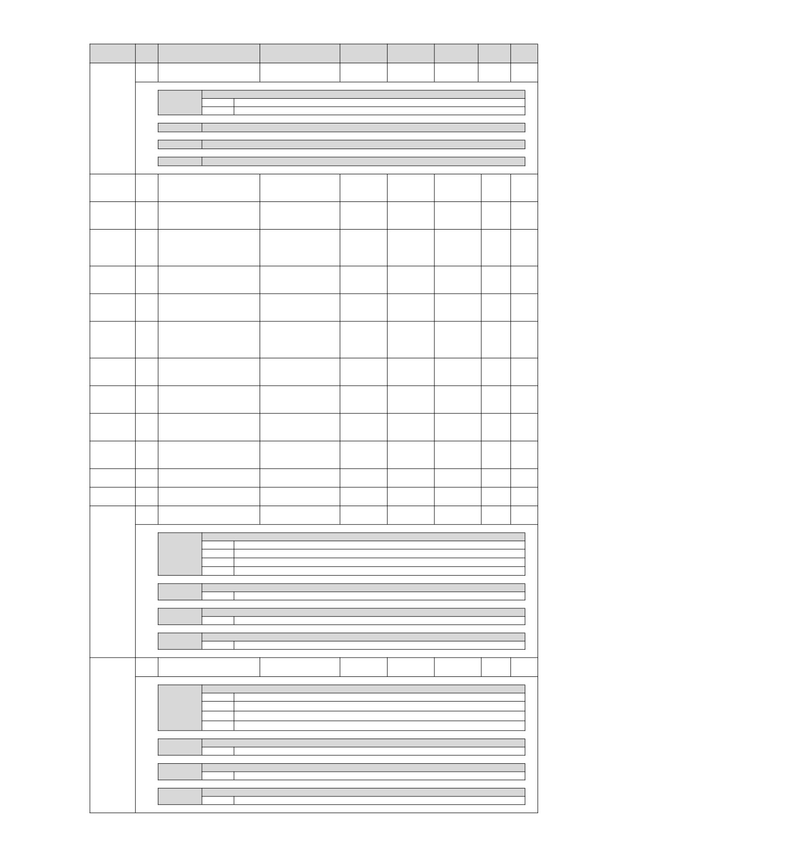
Factory
Available
Categor
Rema
Pn No.
Size
Name
Setting range
Setting Unit
setting
time
y
rks
Power
-
2
Motion setting
0000~0001
-
0000
Setup
restart
n.X
Selection of linear acceleration and deceleration parameters
0
Pn80A~Pn80F, Pn827 are used. (the settings of Pn834 ~ Pn840 are invalid)
1
Pn834~ Pn840 are used. (Pn80A~Pn80F, Pn827 setting invalid)
Pn833
n.X Appointment parameters (do not change it)
n.X Appointment parameters (do not change it)
n.X Appointment parameters (do not change it)
10000
Effective
Section
1
linear
Pn834
4
1~20971520
Command
100
immediately
Setup
acceleration parameter 2
*5
unit/s2
10000
Effective
Section
2
linear
Pn836
4
1~20971520
Command
100
immediately
Setup
acceleration parameter 2
*5
unit/s2
1
Effective
Accelerating
parameter
Command
Pn838
4
0~2097152000
0
immediately
Setup
switching speed 2
unit
*5
/s
10000
Effective
Section
1
linear
Pn83A
4
1~20971520
Command
100
immediately
Setup
deceleration parameter 2
*5
unit/s2
10000
Effective
Section
2
linear
Pn83C
4
1~20971520
Command
100
immediately
Setup
deceleration parameter 2
*5
unit/s2
1
Effective
Deceleration
parameter
Command
Pn83E
4
0~2097152000
0
immediately
Setup
switching speed 2
unit
*5
/s
10000
Effective
Stop
using
linear
Pn840
4
1~20971520
Command
100
immediately
Setup
deceleration parameter 2
*5
unit/s2
100
Effective
Home reset approach
Pn842*8
4
0~20971520
Command
0
immediately
Setup
speed 1 2nd
*5
unit/s
100
Effective
Home reset approach
Pn844
4
0~20971520
Command
0
immediately
Setup
speed 2 2nd
*5
unit/s
POSING command S word
Effective
Pn846
2
acceleration/deceleration
0~50
1%
0
immediately
Setup
-
ratio
*5
Effective
Pn850
2
Latch sequence number
0~8
-
0
Setup
immediately
Number of consecutive
Effective
Pn851
2
0~255
-
0
Setup
latch sequences
immediately
Latch sequence control 1-
Effective
2
0000~3333
-
0000
Setup
4 setting
immediately
n.X
Rotation direction selection
0
C Phase
1
EXT 1 signal
2
EXT 2 signal
3
EXT 3 signal
Pn852
n.X
Latch sequence 2 signal selection
0~3
Same as latch sequence control 1
signal selection.
n.X
Latch sequence 3 signal selection
0~3
Same as latch sequence control 1
signal selection.
n.X
Latch sequence 4 signal selection
0~3
Same as latch sequence control 1
signal selection.
Latch sequence control 5-
Effective
-
2
0000~3333
-
0000
Setup
8 setting
immediately
n.X
Latch sequence 5 signal selection
0
C Phase
1
EXT 1 signal
2
EXT 2 signal
3
EXT 3 signal
Pn853
n.X
Latch sequence 6 signal selection
0~3
Same as latch sequence control 5
signal selection.
n.X
Latch sequence 7 signal selection
0~3
Same as latch sequence control 5
signal selection.
n.X
Latch sequence 8 signal selection
0~3
Same as latch sequence control 5
signal selection.
107
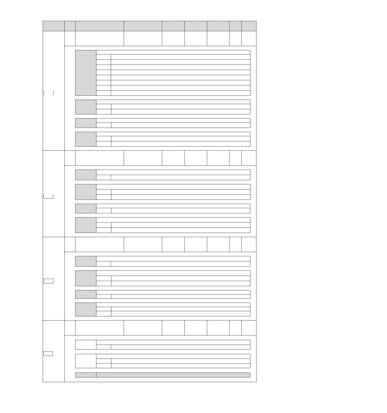
Factory
Available
Categ
Remar
Pn No.
Size
Name
Setting range
Setting Unit
setting
time
ory
ks
SVCMD_IO
(input signal
Effective
2
monitoring)
0000~1717
-
0000
Setup
immediately
Distribution function 1
n.X
Allocation of input signal monitoring for CN1-IN0 (SVCMD_IO)
0
Set CN1-13 input signal monitoring to bit 24 (IO_STS1).
1
Set CN1-13 input signal monitoring to bit 25 (IO_STS2).
2
Set CN1-13 input signal monitoring to bit 26 (IO_STS3).
3
Set CN1-13 input signal monitoring to bit 27 (IO_STS4).
4
Set CN1-13 input signal monitoring to bit 28 (IO_STS5).
5
Set CN1-13 input signal monitoring to bit 29 (IO_STS6).
Pn860
6
Set CN1-13 input signal monitoring to bit 30 (IO_STS7).
M3
7
Set CN1-13 input signal monitoring to bit 31 (IO_STS8).
n.X
Valid/Invalid Selection of Input Signal Monitoring for CN1-IN0
0
Make CN1-IN0 input terminal bit allocation invalid.
1
Make CN1-IN0 input terminal bit allocation valid.
n.X
Allocation of input signal monitoring for CN1-IN1 (SVCMD_IO)
0~7
The allocation is the same as CN1-IN0.
n.X
Valid/Invalid Selection of Input Signal Monitoring for CN1-IN1
0
Make CN1-IN1 input terminal bit allocation invalid.
1
Make CN1-IN1 input terminal bit allocation valid.
SVCMD_IO
(input signal
Effective
2
monitoring)
0000~1717
-
0000
Setup
immediately
Distribution function 2
n.X
Allocation of input signal monitoring for CN1-IN2 (SVCMD_IO)
0~7
The allocation is the same as CN1-IN0.
n.X
Valid/Invalid Selection of Input Signal Monitoring for CN1-IN2
Pn861
0
Make CN1-IN2 input terminal bit allocation invalid.
M3
1
Make CN1-IN2 input terminal bit allocation valid.
n.X
Allocation of input signal monitoring for CN1-IN3 (SVCMD_IO)
0~7
The allocation is the same as CN1-IN0.
n.X
Valid/Invalid Selection of Input Signal Monitoring for CN1-IN3
0
Make CN1-IN3 input terminal bit allocation invalid.
1
Make CN1-IN3 input terminal bit allocation valid.
SVCMD_IO
(input signal
Effective
2
monitoring)
0000~1717
-
0000
Setup
immediately
Distribution function 3
n.X
Allocation of input signal monitoring for CN1-IN4 (SVCMD_IO)
0~7
The allocation is the same as CN1-IN0.
n.X
Valid/Invalid Selection of Input Signal Monitoring for CN1-IN4
Pn862
0
Make CN1-IN4 input terminal bit allocation invalid.
M3
1
Make CN1-IN4 input terminal bit allocation valid.
n.X
Allocation of input signal monitoring for CN1-IN5 (SVCMD_IO)
0~7
The allocation is the same as CN1-13.
n.X
Valid/Invalid Selection of Input Signal Monitoring for CN1-IN5
0
Make CN1-IN5 input terminal bit allocation invalid.
1
Make CN1-IN5 input terminal bit allocation valid.
SVCMD_IO
(input signal
Effective
2
monitoring)
0000~1717
-
0000
Setup
immediately
Distribution function 4
n.X
Allocation of input signal monitoring for CN1-IN6 (SVCMD_IO)
0~7
The allocation is the same as CN1-IN0.
Pn863
M3
n.X
Valid/Invalid Selection of Input Signal Monitoring for CN1-IN6
0
Make CN1-IN6 input terminal bit allocation invalid.
1
Make CN1-IN6 input terminal bit allocation valid.
n.X X
Appointment parameters (do not change it)
108
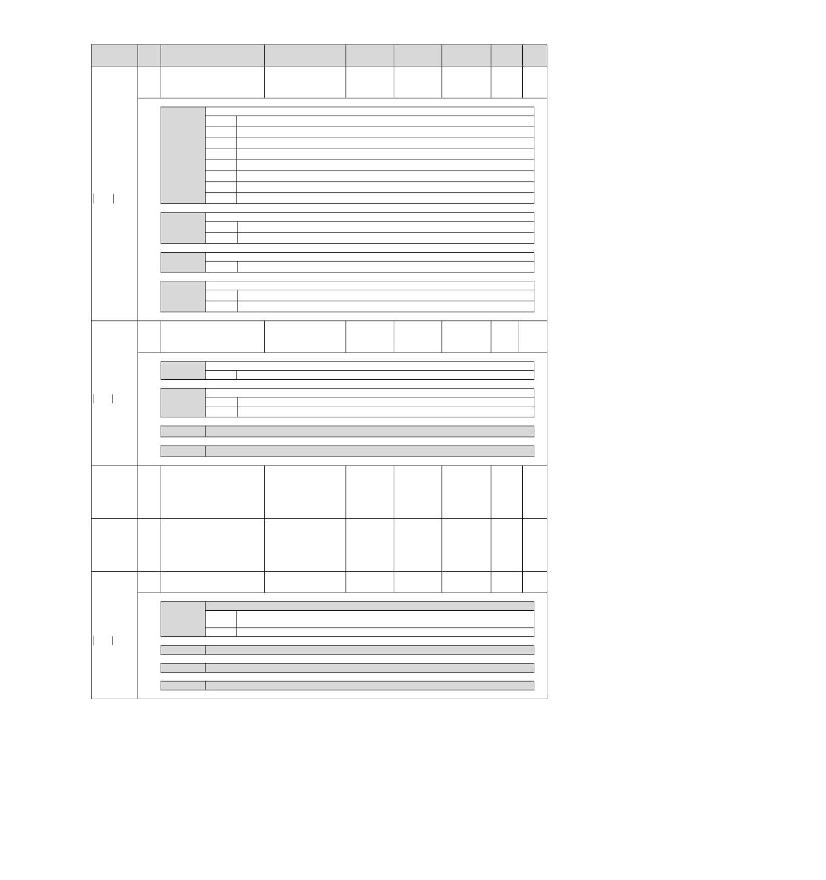
Factory
Available
Catego
Rem
Pn No.
Size
Name
Setting range
Setting Unit
setting
time
ry
arks
SVCMD_IO (output signal
Effective
2
monitoring)
0000~1717
-
0000
Setup
immediately
Distribution function 1
n.X
Distribution of output signal monitoring for CN1-OUT1 (SVCMD-IO)
0
Set CN1-OUT1 output terminal monitoring to D24 (IO1_ STS1).
1
Set CN1-OUT1 output terminal monitoring to D25 (IO1_ STS1).
2
Set CN1-OUT1 output terminal monitoring to D26 (IO1_ STS1).
3
Set CN1-OUT1 output terminal monitoring to D27 (IO1_ STS1).
4
Set CN1-OUT1 output terminal monitoring to D28 (IO1_ STS1).
5
Set CN1-OUT1 output terminal monitoring to D29 (IO1_ STS1).
Pn868
6
Set CN1-OUT1 output terminal monitoring to D30 (IO1_ STS1).
M3
7
Set CN1-OUT1 output terminal monitoring to D31 (IO1_ STS1).
n.X
Output signal monitoring selection for CN1-OUT1
0
Make CN 1-OUT1 output terminal monitoring allocation invalid.
1
Make CN1 - OUT1 output terminal monitoring allocation valid.
n.X
Distribution of output signal monitoring for CN1-OUT2 (SVCMD-IO)
0~7
The allocation is the same as CN1-OUT1.
n.X
Output signal monitoring selection for CN1-OUT2
0
Make CN 1-OUT2 output terminal monitoring allocation invalid.
1
Make CN1 - OUT2 output terminal monitoring allocation valid.
SVCMD_IO (output signal
Effective
2
monitoring)
0000~1717
-
0000
Setup
immediately
Distribution function 2
n.X
Distribution (SVCMD-IO)of output signal monitoring for CN1-OUT3
0~7
The allocation is the same allocation of CN1-OUT1.
Pn869
n.X
Output signal monitoring selection for CN1-OUT3
M3
0
Make CN1-OUT3 output terminal monitoring allocation invalid.
1
Make CN1 - OUT3 output terminal monitoring allocation valid.
n.X
Appointment parameters (do not change it)
n.X
Appointment parameters (do not change it)
Transmission cycle setting
monitoring
Effective
Pn882
2
[0.25 µs]
0〜FFFF
-
0
Setup
-
immediately
(for maintenance, viewing
only)
Communication
cycle
setting monitoring
Effective
Pn883
2
[xTransmission period]
0~32
-
0
Setup
-
immediately
(for maintenance, viewing
only)
Effective
2
Communication control 2
0000~0001
-
0000
Setup
immediately
n.X
Setting of brake signal in abnormal MECHATROLINK communication
When MECHATROLINK communication is abnormal, the set state is maintained
0
through BRK _ ON and BRK _ OFF commands.
Pn884
1
When MECHATROLINK communication is abnormal, set the brake to active.
M3
n.X Appointment parameters (do not change it)
n.X Appointment parameters (do not change it)
n.X Appointment parameters (do not change it)
*1. Percentage relative to rated torque of motor.
*2. Generally set to "0". The capacity value (W) of the regenerative resistor is set when the external regenerative resistor is used.
*3. The upper limit value is the maximum output capacity (W) applicable to servo drive.
*4. Valid parameters only for MECHATROLINK-III standard servo configuration file.
*5. SENS_ON takes effect.
*6. Changes in actions will affect command output, so please change in the state of command stop (DEN=1).
*7. The value is updated only when the command is stopped (DEN=1).
*8. Parameters valid only when MECHATROLINK-II is compatible with configuration files.
109
Chapter 11 Operation of Debugging Software (iWatch+)
The following functions can be realized online by using the upper computer software (iWatch+):
• Parameter management: parameter setting and adjustment
• State monitoring: monitoring the working state and relevant data of the servo system
• Tracking: tracking the servo power supply, command, output current and other related data
• Auxiliary debugging: realize various functions of online auxiliary debugging servo with upper computer
11.1 Connection and login of iWath+ debugging software
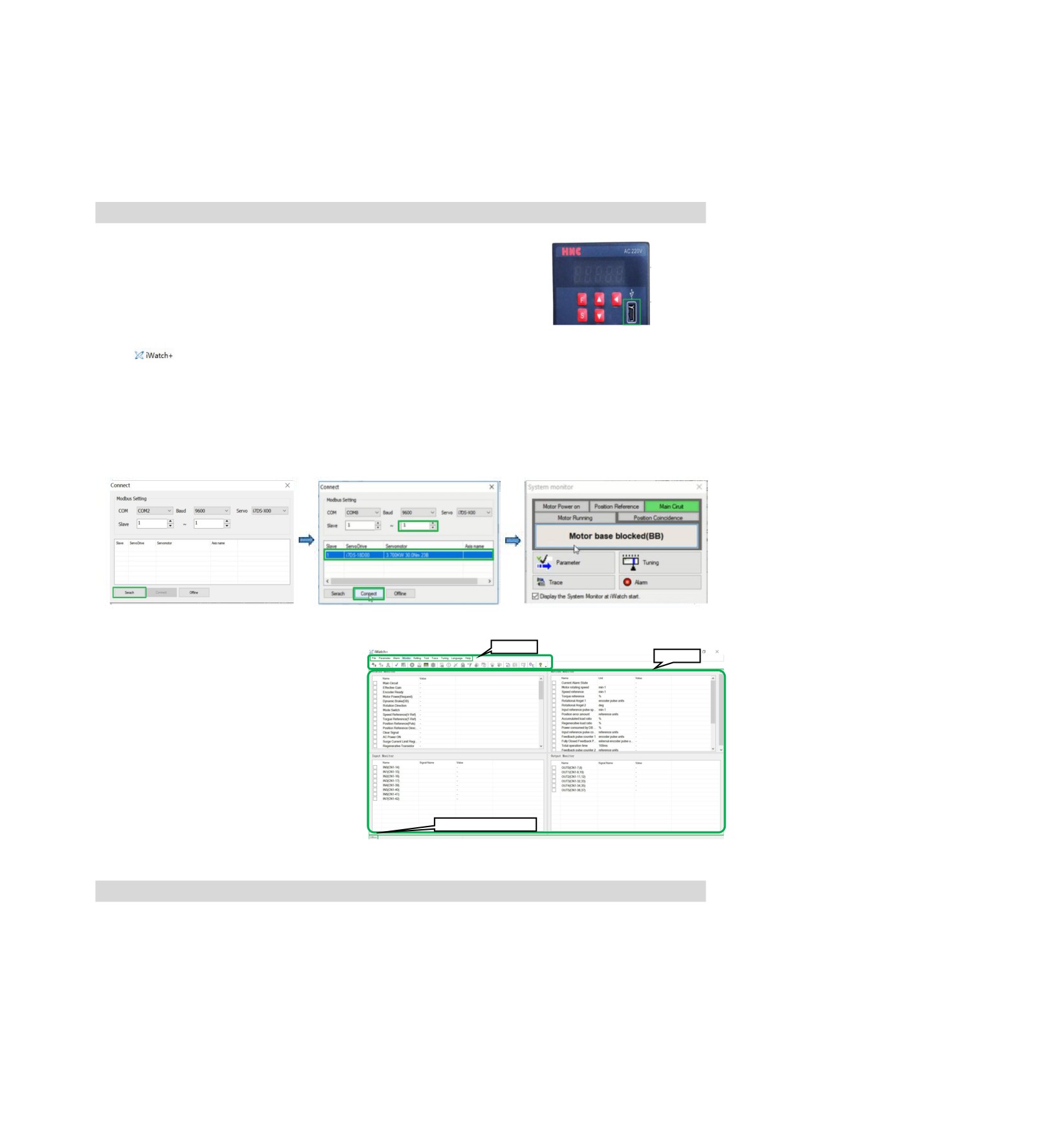
1. Install iWatch+ debugging software on PC
2. The PC is connected to the Mini USB interface on the servo driver panel
operator through a USB connection line. The communication interface is
shown in the right figure.
3. After the communication lines are correctly connected, execute iWatch+ debugging software (icon) on
the PC.
After displaying the [User Login] window, click the [Search] button (Figure 1).
(Two-axis drive selects slave station addresses 1 ~ 2, and the searched address 1 is the drive A axis and
address 2 is the drive B axis)
4. After the [Connect] window is displayed, select the searched drive address 1 or address 2, and then click
the [Connect] button (Figure 2).
5. The [system monitoring] shortcut window (Figure 3) and the [iWatch+] debugging window (Figure 4) will be
displayed after successful connection.
Figure 1
Figure 2
Figure 3
Shortcut
Monitoring
At this time, iWatch+ debugging software is
successfully connected.
yIn the [iWatch+] debugging window, various
states of servo can be selectively monitored
in each window.
yIn the menu bar of the [iWatch+] debugging
Communication status
window, you can click the shortcut button for
debugging to enter the debugging interface.
11.2 Automatic adjustment (no upper command)
Automatic adjustment (no upper command) refers to the function that the servo unit performs automatic
operation (reciprocating motion of forward rotation and reverse rotation) without issuing a command from the
upper device and adjusts according to mechanical characteristics during operation.
The automatic adjustment items are as follows.
• Moment of inertia ratio
• Gain adjustment (speed loop gain, position loop gain, etc.)
• Filter adjustment (torque command filter, notch filter)
• Friction compensation
• Type A vibration suppression control
• Vibration abatement
110
The following describes the adjustment of automatic adjustment (no upper command).
• The automatic adjustment (without a bit command) is based on the set speed loop gain (Pn100). If vibration
occurs at the beginning of the adjustment, the correct adjustment cannot be made. Please reduce the speed
loop gain (Pn100) until it stops vibrating and adjust.
• When the adjustment-free function is valid (Pn170 = n. 1 [factory setting]), automatic adjustment (no
upper command) cannot be performed. Please set the adjustment-free function to invalid (Pn170 = n.
0) and adjust.
• After performing the automatic adjustment (without the upper command), change the load state of the
machine or the transmission mechanism, etc. When setting the "Estimated Moment of Inertia" again to
perform the automatic adjustment (without the upper command), please set the following parameters. If the
automatic adjustment is performed in a state other than the following (no upper command), mechanical
vibration and mechanical damage may be caused.
Pn140 = n. 0 (without model tracking control)
Pn160 = n. 0 (type a vibration suppression control is not used)
Pn408=n.000 (no friction compensation, 1st and 2nd notch filters used)
(Note) If the above parameters are not displayed when using the digital operator, please select the
settings (PN00B = n. 1) to display all parameters and switch on the power again.
■ Confirmation before execution
Be sure to confirm the following settings before performing the automatic adjustment (no upper command).
• The main circuit power supply must be ON.
• No over-travel is allowed.
• Must be in servo OFF state.
• Not for torque control.
• The gain switch selection switch must be manual gain switch (Pn139 = n. 0).
• Gain 1 must have been selected.
• No motor test function selection must be invalid (Pn00C = n. 0).
• No alarm or warning shall be generated.
• Hardware Base Blocking (HWBB) function must be invalid.
• The write inhibit setting of the parameter must not be set to "write inhibit"
• The adjustment-free function must be set to invalid (Pn170=n. 0) or "estimated moment of inertia"
when the adjustment-free function is set to valid (Pn170 = n. 1)
• The mode selection must be set to 1 when executing in the state of speed control
Operating Steps
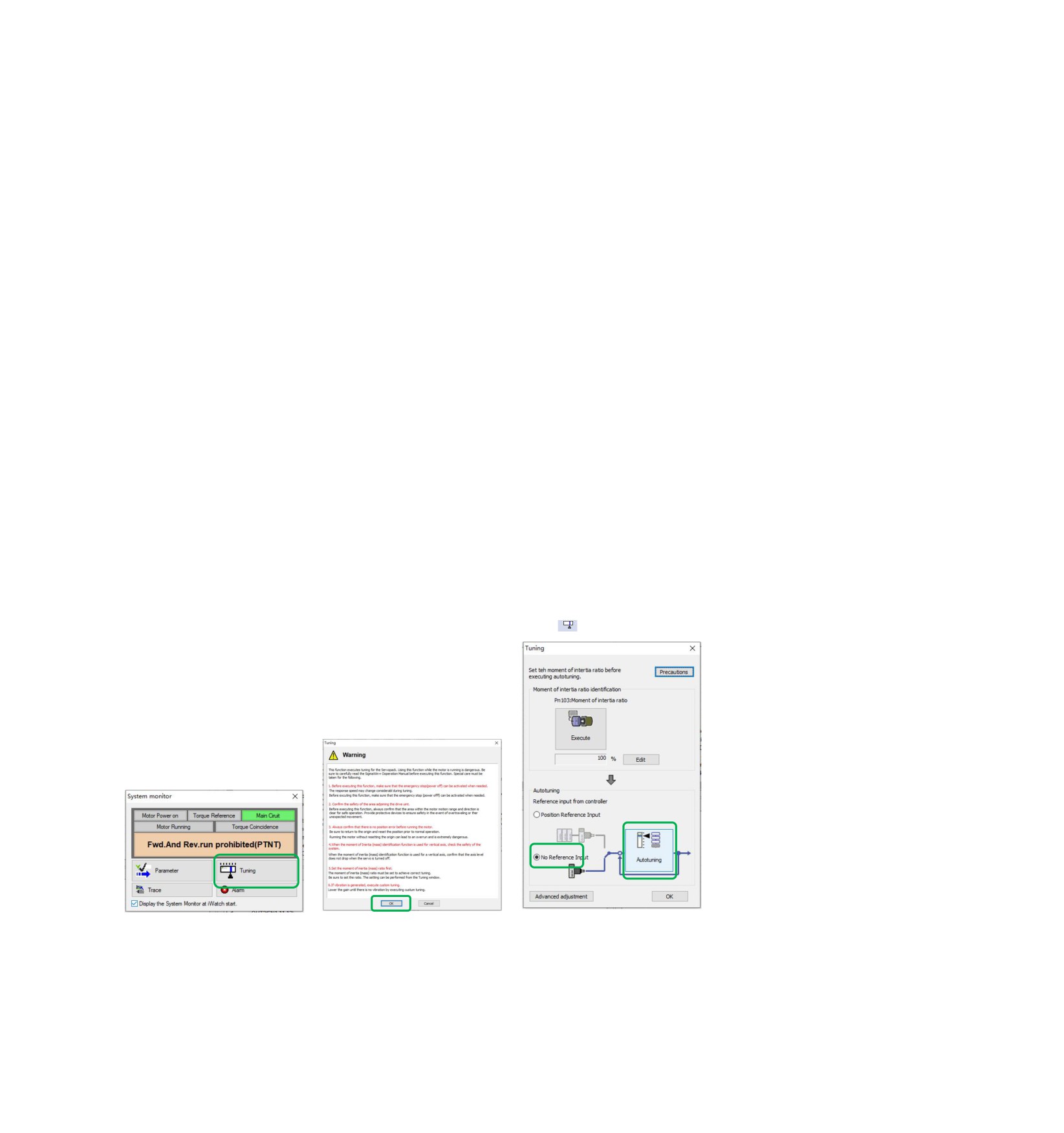
1. Confirm that the rotational inertia ratio (Pn103) has been correctly set.
2. Connect the servo driver and click the "Tune" button in the working area of the iWatch+ [System Detection]
window (Figure 5).
Or click the tune shortcut button (icon) from the shortcut menu of the [iWatch+]
debug window.
3. Enter the [Tuning] window and click the [Execute] button (Figure 6).
4. Enter the [Tuning Axis] window (Figure 7)
Select the [Auto Tuning] group
Select [No Reference Input]
Click the [Auto Tuning] button
Figure 5
Figure 6
Figure 7
5. Enter the [Auto Tuning Setting Conditions] window (Figure 8)
Set separately
• [Select Load Moving Inertia Marker] Column
• [Mode Selection] Column
• [Institutional choice] column
• [Distance] column
• [Tuning Parameters] column
Then click [Next]
111
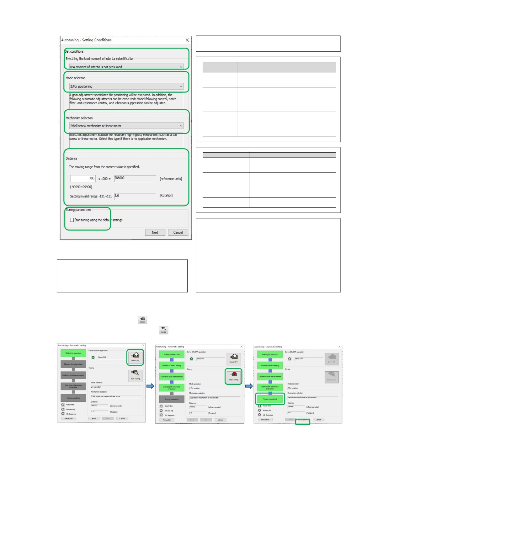
• Select the load movement inertia mark
0: No estimation of moving inertia [factory setting]
1. Estimated moment of inertia
Selection pattern
Selection
Description
pattern
Make standard gain adjustments. In addition to
1: Standard
gain adjustment, notch filter and Type A vibration
suppression are automatically adjusted.
Make special adjustment for positioning purpose.
In addition to gain adjustment, model tracking
2: Location
control, notch filter, type A vibration suppression
and vibration suppression are also automatically
adjusted.
In the positioning application, it is necessary to
3: Location
pay attention to the adjustment without overshoot.
(Pay attention
In addition to gain adjustment, notch filter, type A
not to
vibration suppression and vibration suppression
overshoot)
are automatically adjusted.
• Institutional choice
Institutional choice
Description
Adjustments suitable for less rigid
1. Belt transmission
mechanisms such as belt mechanisms are
mechanism
made.
The adjustment is suitable for high rigidity
2.
Ball
screw
mechanisms such as ball screw
mechanism or
linear
mechanisms or linear servo motors. Please
servo mechanism
select this type when there is no
corresponding organization.
3.
Rigid
body
Adjust the mechanism with higher rigidity
mechanism
such as rigid body system.
• Distance
Set the moving distance.
Movement Range:-99990000 ~+99990000 [Command Unit]
Minimum setting scale for moving distance: 1000 [command unit]
Initial settings value:
Figure 8
The rotary servo motor rotates about 3 times.
Directly drive the servo motor for about 0.3 coils
Linear servo motor approx. 90mm
Please set the value above the following value. In addition, in order to
• Tuning parameters
Specify the adjustment parameters to use.
ensure the adjustment accuracy, it is recommended to set the moving
If the
[Start Tuning with Default] check
box
is
checked,
the
distance around the initial set value.
adjustment will be performed after the adjustment parameters
The rotary servo motor rotates 0.5 coils.
return to the factory state.
Directly drive the servo motor for 0.05 coils
Linear servo motor 5mm
6. Enter the [Auto Tuning] window
Click the [Servo On] button (
icon) to energize the servo motor.
Next, click the [Start Tuning] button (
icon) to rotate the servo motor and perform adjustment.
The vibration generated in the adjustment is automatically detected and the generated vibration is optimally
set.
The executed function frame will light up after the setting is completed
7. Click the [Finish] button to return to the [Tuning Axis] window after tuning is completed.
Then, the operation of automatic adjustment (no upper command) is completed.
112
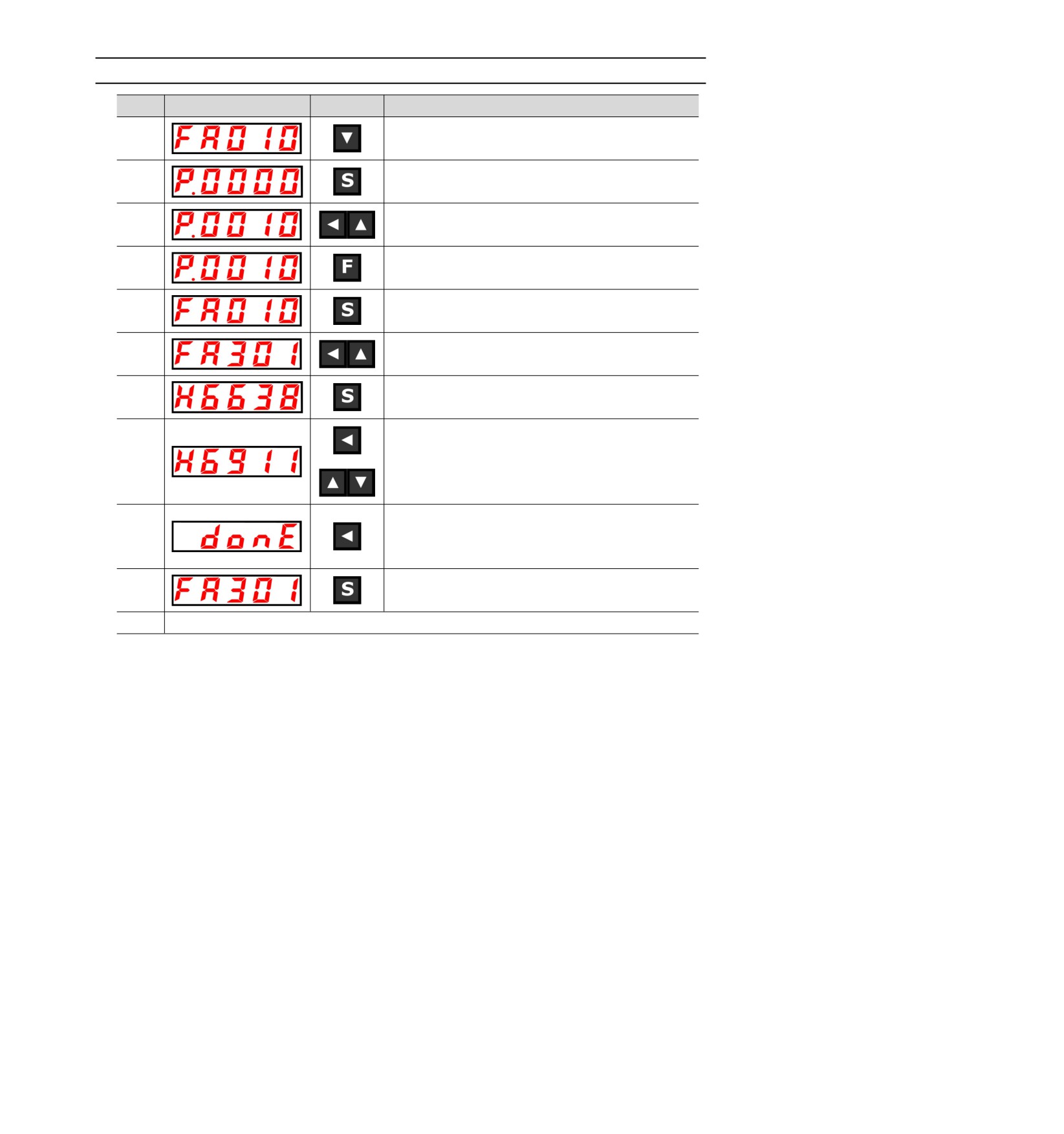
Motor code is written to encoder EEROM operation(FA301)
Step
Display
Key
Operation
1
Press the left button and UP button to display "FA010".
2
Press the S key, the display content is shown on the left.
Press the left button and UP button to enter the advanced
3
authority P.0010.
Press F to confirm the setting. After the setting is completed,
4
“donE” flashes and returns to the display on the left.
5
Press the S key to return to the "FA010" display.
6
Press the left button and the UP button to display "FA301".
7
Press the S key, the display content is shown on the left.
Set the correct motor code according to the actual model of the
8
current motor.
Press and hold the left button until "doing" is displayed; when
9
"done" flashes, it means that the motor code has been
successfully written.
10
Press the S key to return to the "FA301" display.
11
Need to restart HSD7 for all settings to take effect
113
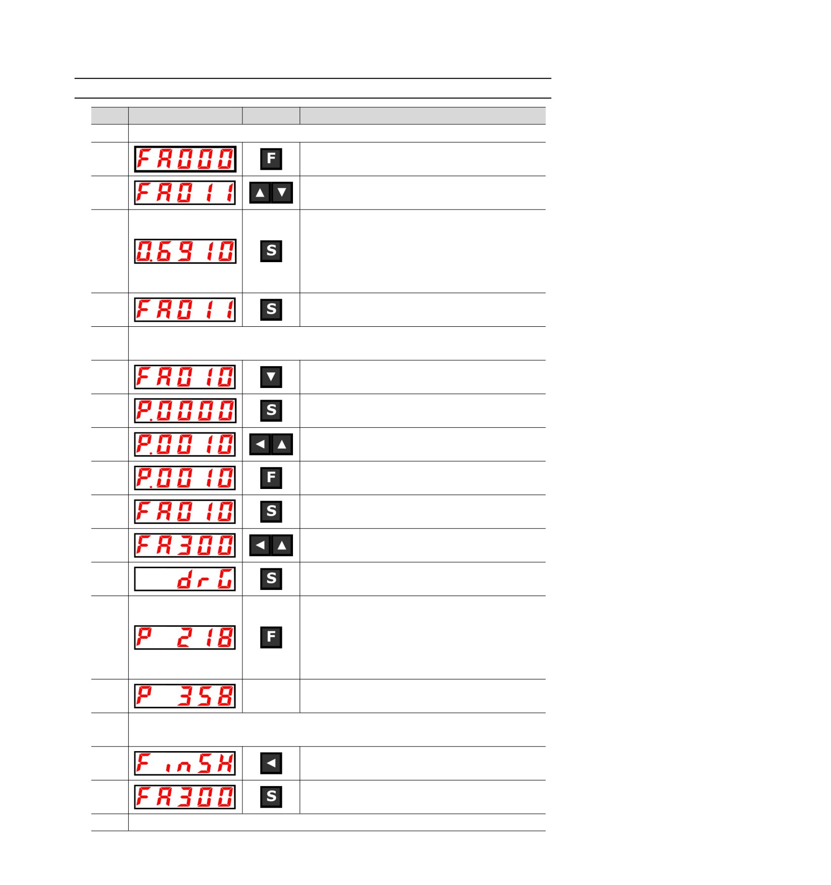
Motor zero position check and reset operation (FA300)
Step
Display
Key
Operation
1
Perform this operation, the motor must without load! ! !
2
Press F to select auxiliary function.
3
Press the UP or DOWN key to display "FA011".
Press the S key, the display content is as shown on the left,
"0.6910" means the current motor code, if the code is
4
inconsistent with the current connected motor, Please correct it
by FA301 (Operation of motor code written into encoder
EEROM) or manually set motor code by parameter.
5
Press S again to return to "FA011" display.
Make sure that the current motor code of the servo drive is the same as the motor code of the actual operating
6
motor, otherwise do not perform the subsequent steps! ! !
7
Press the DOWN key to display "FA010".
8
Press the S key, the display content is shown on the left.
Press the left button and UP button to enter the advanced
9
authority P.0010.
Press F to confirm the setting. After the setting is completed,
10
“donE” flashes and returns to the display on the left.
11
Press the S key to return to the "FA010" display.
12
Press the left button and the UP button to display "FA300".
13
Press the S key, the display content is shown on the left.
Press the F key to start the magnetic pole zero search. At this
time, the motor starts to rotate slowly, and the electrical angle
14
of the motor is displayed in real time.Note: The rotating motor
must rotate counterclockwise, otherwise the C50 alarm will
appear, please confirm the UVW wiring is correct.
After waiting for the motor to stop, the current display "358" is
15
the motor pole zero angle.
If you only want to check the motor pole angle, press S to exit; if you need to clear the motor pole zero angle
16
to the zero degree position, you can perform the following operations! !
Press and hold the left button until the digital tube displays
17
"FiniSH", and the current motor pole zero angle is set to zero.
18
Press the S key to return to the "FA300" display.
19
Need to restart HSD7 for all settings to take effect
114