Ransomes Frontline 960 (Engine Type: Perkins 404C-22T). Parts and Maintenance Manual (2002) - page 1
24598G (rev.0)
Parts and Maintenance Manual
Nomenclature Des Pieces De Rechange
& Manuel De Maintenance
Onderhouds - En Onderdelenhandleiding
Wartungsanleitung Und Stückliste
Manuale Per La Manutenzione E Dei Ricambi
Frontline 960
Series: LQ
Engine Type: Perkins 404C-22T
Product Codes: LHAM001
WARNING: If incorrectly used this machine can cause severe
injury. Those who use and maintain this machine should be
trained in its proper use, warned of its dangers and should
read the entire manual before attempting to set up, operate,
adjust or service the machine.
AVERTISSEMENT : Risque de blessures graves en cas
d’utilisation incorrecte de la machine. Les opérateurs et le
personnel d’entretien doivent être formés et conscients des
dangers encourus. Ils doivent lire avec attention le manuel
avant d’essayer de monter, d’utiliser, de régler ou maintenir la
machine.
WAARSCHUWING: Bij verkeerd gebruik kan deze machine
ernstig lichamelijk letsel veroorzaken. Degenen die de machine
gebruiken en onderhouden moeten worden getraind in het
juiste gebruik ervan, worden gewaarschuwd voor de
gevaren ervan en behoren de volledige handleiding
aandachtig te lezen alvorens de machine bedrijfs-klaar te
maken, te bedienen, af te stellen en/of te onderhouden.
WARNHINWEIS: Wenn diese Maschine nicht ordnungsgemäß
verwendet wird, können ernsthafte Verletzungen verursacht
werden. Personen, die diese Maschine verwenden und
warten, müssen in ihrer richtigen Verwendung ausgebildet
sein, auf die Gefahren aufmerksam gemacht worden sein
und die Anleitung ganz gelesen haben, bevor sie versuchen,
die Maschine aufzustellen, zu bedienen, einzustellen oder
zu warten.
AVVERTENZA: Questa macchina può causare gravi infortuni
se viene utilizzata in modo errato. Prima di accingersi ad
approntare, usare, mettere a punto o eseguire la manutenzione
di questa macchina, coloro che la utilizzano ed i responsabili
della manutenzione devono essere addestrati all’impiego della
macchina, devono essere informati dei pericoli, e devono
leggere l’intero manuale.
RJ 100 / 082002
1
CONTENTS
FRONTLINE 960 Series: LQ
MAINTENANCE AND PARTS MANUAL
GB
1
CONTENTS
2
INTRODUCTION
2.1
PRODUCT IDENTIFICATION
2
2.2
SPARES STOCKING GUIDE
2
2.3
HOW TO USE THE PARTS MANUAL
3
3
SAFETY INSTRUCTIONS
3.1
OPERATING INSTRUCTIONS
4
3.2
SAFETY SIGNS
4
3.3
STARTING THE ENGINE
4
3.4
DRIVING THE MACHINE
4
3.5
TRANSPORTING
4
3.6
LEAVING THE DRIVING POSITION
5
3.7
SLOPES
5
3.8
BLOCKED CUTTING CYLINDERS
5
3.9
ADJUSTMENTS, LUBRICATION AND MAINTENANCE
5/6
4
SPECIFICATION
4.1
ENGINE SPECIFICATION
7
4.2
MACHINE SPECIFICATION
7
4.3
DIMENSIONS
7
4.4
VIBRATION LEVEL
7
4.5
SLOPES
7
4.6
RECOMMENDED LUBRICANTS
8
4.7
CUTTING PERFORMANCE (AREA)
8
4.8
TORQUES
8
5
LUBRICATION AND MAINTENANCE
LUBRICATION AND MAINTENANCE CHARTS
9/10
5.1
ENGINE: FIRST 50 WORKING HOURS AND EVERY 250 WORKING HOURS
11
5.2
MACHINE: LUBRICATE THE FOLLOWING POINTS WITH SHELL
DARINA R2 GREASE WEEKLY (EVERY 40 WORKING HOURS):
11
5.3
MACHINE: EVERY 400 WORKING HOURS
12
5.4
HYDRAULIC TEST PORTS
13
5.5
ENGINE MAINTENANCE: EVERY 250 HRS
14
5.6
ENGINE MAINTENANCE: EVERY 400 HRS
15
5.7
MACHINE MAINTENANCE
15
5.8
END OF SEASON SERVICING
16
6
ADJUSTMENTS
6.1
SPEED LIMITER
17
6.2
REAR WHEEL TOE-IN
17
6.3
ALTERNATOR
17
7
CUTTER DECK ADJUSTMENTS
7.1
CUTTER DECK TENSION
18
7.2
BLADE SHARPENING & REMOVAL
19
8
TROUBLESHOOTING
8.1
GENERAL
19
9
SCHEMATICS
9.1
HYDRAULIC CIRCUIT
20
9.2
ELECTRICAL CIRCUIT INSTRUMENT
21
9.3
ELECTRICALCIRCUIT MAIN
22
9.4
ELECTRICAL FUSES/RELAYS
23/24
PARTS LIST
PARTS-1
GB-1
2
INTRODUCTION
FRONTLINE 960 Series: LQ
MAINTENANCE AND PARTS MANUAL
GB
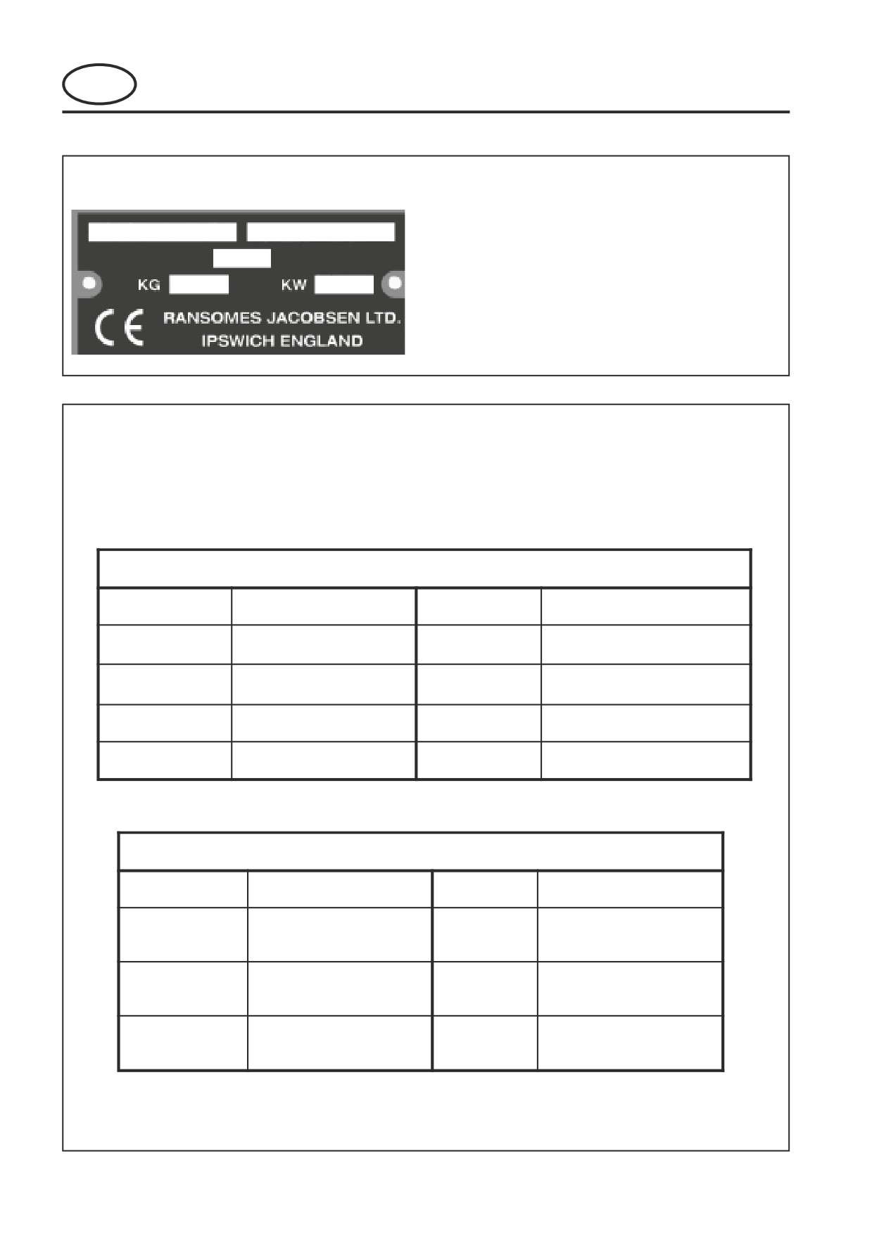
2.1 PRODUCT IDENTIFICATION
A Machine Name
A
B
B Serial Number
C
C Year of Manufacture
D Machine Weight
D
E
E Engine Power
2.2
SPARES STOCKING GUIDE
To keep your equipment fully operational and productive, Ransomes suggests you maintain a stock of the more
commonly used maintenance items. We have included part numbers for the additional support materials and
training aids.
Service Parts
Part No
Description
Part No.
Description
Engine Oil Filter
178025
Hydra
l
26560017
Engine Fuel Filter
4126806
Electric Fuel Pump
4123044
Air Cleaner Element
5001182
In-line Fuel Filter
008089620
Hydra
l
Service Support Material
Part No
Description
Part No.
Description
Machine Maintenance
Engine Parts Manual
24598G
and Parts Manual
Engine Operators
Machine Safety and
24597G
Manual
Operators Manual
Engine Service
Machine Service
-
Manual
Manual
GB-2
2
INTRODUCTION
FRONTLINE 960 Series: LQ
MAINTENANCE AND PARTS MANUAL
GB
2.3
HOW TO USE THE PARTS MANUAL
ITEM NUMBER
Each part which is identified in the illustrations has an item number. Parts which do not have an item number
may not be readily identified in the illustration but are usually closely associated with the immediately adjacent
part.
ASSEMBLIES
A complete assembly, e.g. a wheel motor or hydraulic motor or roll assembly, is listed as a complete item with
subsequent individual components listed separately.
The assembly is listed under it's part number with component parts being listed offset to the right, e.g:-
ITEM RANSOMES DESCRIPTION
QTY REMARKS
PART NO.
4295
MBG2504
BRACKET
1
4296
MBG3848
LATCH
2
4298
450865
SCREW, M8 x 20, SCKT CSK HD
2
4300
450378
NUT, M8 NYLOC
2
4301
Wl001
Set Of Wheels
1
4301.1
008162130
• Wheel & Hub Assy
1
(Rear)
4301.2
008170390
• • Tyre
1
4301.3
008161830
• • Rim
1
4301.4
008169140
• • Hub Assy.
1
4301.5
008169150
• • Cap
1
4301.6
002993010
• • Lubricator
1
4301.7
008161990
• Wheel & Tyre
2
(Front)
4301.8
008170780
• • Tyre
2
It may not be possible to illustrate every item. With certain items purchased from outside suppliers some
component parts may not be available from Ransomes and may need to be specially ordered from the supplier.
QUANTITIES
Quantities shown are for one assembly or sub-assembly.
USING THE PARTS LIST
Determine the function and application of the part required. Turn to the main index page and select the
appropriate section. Locate the part on the illustration and parts list and read off the quantity from the
appropriate MODEL column.
NUMERICAL INDEX
This is a summary of all part numbers used in the manual arranged in numerical sequence and showing the
page and item number under which the parts appear.
ORDERING OF SPARE PARTS
When ordering replacement parts, it is most important to quote the SERIAL NUMBER of the machine, PART
NUMBER, DESCRIPTION and QUANTITY required.
Spare Parts can also be ordered direct from the TEXTRON DIRECT web site at www.textrondirect.com
Any arbitrary modifications carried out on this machine may relieve the manufacturer of liability for any resulting
damage or injury.
ABBREVIATIONS
N/A Not Available
AR As Required
GB-3
3
SAFETY INSTRUCTIONS
FRONTLINE 960 Series: LQ
MAINTENANCE AND PARTS MANUAL
GB
This safety symbol indicates important safety
•
Remember that some people are deaf
messages in this manual. When you see this
or blind and that children and animals
symbol, be alert to the possibility of injury, carefully
can be unpredictable.
read the message that follows, and inform other
•
Keep travelling speeds low enough for
operators.
an emergency stop to be effective and
safe at all times, in any conditions.
3.1 OPERATING INSTRUCTIONS
•
Remove or avoid obstructions in the
•
Ensure that the instructions in this book
area to be cut, thus reducing the
are read and fully understood.
possibility of injury to yourself and/or
•
No person should be allowed to operate
bystanders.
this machine unless they are fully
•
When reversing, take special care to
acquainted with all the controls and the
ensure that the area behind is clear of
safety procedures.
obstructions and/or bystanders. DO
•
Never allow children or people unfamiliar
NOT carry passengers.
with these instructions to usethis
•
Keep in mind that the operator or user is
machine. Local regulations may restrict
responsible for accidents or hazards
the age of the operator.
occurring to other people or their
property.
3.2 SAFETY SIGNS
•
When the machine is to be parked,
•
It is essential all safety labels are kept
stored or left unattended, lower the
legible, if they are missing or illegible they
cutting means unless the transport
must be replaced. If any part of the
locks are being used.
machine is replaced and it originally
•
While mowing, always wear substantial
carried a safety label, a new label must be
footwear and long trousers. Do not
affixed to the replacement part. New
operate the equipment when barefoot or
safety labels are obtainable from
wearing open sandals.
Ransomes dealers.
•
Check the grass catcher frequently for
wear or deterioration. After striking a
3.3 STARTING THE ENGINE
foreign object. Inspect the lawnmower
•
Before starting the engine check that the
for damage and make repairs before
brakes are applied, drives are in neutral,
restarting and operating the equipment.
guards are in position and intact, and
•
If the machine starts to vibrate
bystanders are clear of the machine.
abnormally, check immediately.
•
Do not run the engine in a building without
adequate ventilation.
3.5 TRANSPORTING
•
Ensure that the cutting units are
3.4 DRIVING THE MACHINE
securely fastened in the transport
•
Before moving the machine, check to
position. Do not transport with cutting
ensure that all parts are in good working
mechanism rotating.
order, paying particular attention to
•
Drive the machine with due
brakes, tyres, steering and the security of
consideration of road and surface
cutting blades.
conditions, inclines and local
•
Replace faulty silencers, mow only in
undulations.
daylight or good artificial light
•
Sudden decelerating or braking can
•
Always observe the Highway Code both
cause the rear wheels to lift.
on and off the roads. Keep alert and
•
Remember that the stability of the rear
aware at all times. Watch out for traffic
of the machine is reduced as the fuel is
when crossing or near roadways.
used.
•
Stop the blades rotating before crossing
surfaces other than grass.
GB-4
3
SAFETY INSTRUCTIONS
FRONTLINE 960 Series: LQ
MAINTENANCE AND PARTS MANUAL
GB
3.6 LEAVING THE DRIVING POSITION
•
To reduce the fire hazard, keep the engine,
•
Park the machine on level ground.
silencer and battery compartments free of
grass, leaves or excessive grease.
•
Before leaving the driving position, stop
•
Replace worn or damaged parts for safety.
the engine and make sure all moving
•
When working underneath lifted parts or
parts are stationary. Apply brakes and
machines, make sure adequate support Is
disengage all drives. Remove the starter
provided.
key.
•
Do not dismantle the machine without
releasing or restraining forces which can
3.7 SLOPES
cause parts to move suddenly.
TAKE EXTRA CARE WHEN WORKING ON
•
Do not alter engine speed above maximum
SLOPES
quoted in Engine Specification. Do not
•
Local undulations and sinkage will change
change the engine governor settings or
the general slope. Avoid ground
overspeed the engine. Operating the engine
at excessive speed may increase the hazard
conditions which can cause the machine
of personal injury.
to slide.
•
When refuelling, STOP THE ENGINE, DO
•
Keep machine speeds low on slopes and
NOT SMOKE. Add fuel before starting the
during tight turns.
engine, never add fuel while the engine is
•
Sudden decelerating or braking can
running.
cause the rear wheels to lift. Remember
•
Use a funnel when pouring fuel from a can
there is no such thing as a “safe” slope.
into the tank.
•
Travel on grass slopes requires particular
•
Do not fill the fuel tank beyond the bottom of
care.
the filler neck.
•
Replace all fuel tank and container caps
DO NOT USE ON SLOPES GREATER THAN 15°
securely.
•
Store fuel in containers specifically designed
for this purpose.
IMPORTANT: When working on any slope set the
•
Refuel outdoors only and do not smoke while
weight transfer, if fitted to its maximum (+) setting.
refuelling.
•
If fuel is spilled, do not attempt to start the
3.8 BLOCKED CUTTING CYLINDERS
engine but move the machine away from the
•
Stop the engine and make sure all moving
area of spillage and avoid creating any
parts are stationary.
source of ignition until fuel vapours have
•
Apply brakes and disengage all drives.
dissipated.
•
Release blockages with care. Keep all parts
•
Allow the engine to cool before storing in any
of the body away from the cutting edge.
enclosure.
Beware of energy in the drive which can
•
Never store the equipment with fuel in the
cause rotation when the blockage is
tank inside a building where fumes may
released.
reach an open flame or spark.
•
Keep other people away from the cutting
•
If the fuel tank has to be drained, this should
units as rotation of one cylinder can cause
be done outdoors.
the others to rotate.
•
Do not spill fuel onto hot components.
•
When servicing batteries, DO NOT SMOKE,
3.9 ADJUSTMENTS, LUBRICATION AND
and keep naked lights away.
MAINTENANCE
•
Do not place any metal objects across the
•
Stop the engine and make sure all moving
terminals.
parts are stationary.
•
Apply brakes and disengage all drives.
•
Read all the appropriate servicing
instructions.
•
Use only the replacement parts supplied by
the original manufacturer.
•
When adjusting the cutting cylinders take
care not to get hands and feet trapped when
rotating cylinders.
•
Make sure that other people are not touching
any cutting units, as rotation of one cylinder
can cause the others to rotate.
GB-5

3
SAFETY INSTRUCTIONS
FRONTLINE 960 Series: LQ
MAINTENANCE AND PARTS MANUAL
GB
DANGER - Indicates an imminently hazardous
IMPORTANT: Transport speed is for highway
situation which, if not avoided, WILL result in
use only. Never select transport speed
death or serious injury.
on grass areas or uneven or unsurfaced
roads or tracks.
WARNING - Indicates a potentially hazardous
situation which, if not avoided, COULD result
The operating instruction for the Cutting Units are
in death or serious injury.
contained in a separate Publication.
CAUTION - Indicates a potentially hazardous
situation which, if not avoided, MAY result in
minor or moderate injury and property
damage. It may also be used to alert against
unsafe practices.
WARNING
WARNING
California Proposition 65
Engine Exhaust, some of its constituents,
Hydraulic Fluid escaping under pressure
and certain vehicle components contain or
can penetrate skin and do serious
emit chemicals known to the state of
damage. Immediate medical assistance
California to cause cancer and birth defects or
must be sought.
other reproductive harm
WARNING
WARNING
Batteries produce explosive gases and
DO NOT USE ON SLOPES GREATER THAN 15°
contain corrosive acid and supply levels
of electrical current high enough to cause
burns.
WARNING
Before releasing transport latches it is
important that all cutting units are fully raised.
1.
Park the machine on level ground.
2.
With the engine running at operating
speed raise the cutting units to their
maximum position by operating lift
levers whilst seated in the driving
position.
3.
Disengage drives, stop the engine and
make sure all moving parts are
stationary. Apply brakes and remove
the starter key.
4.
transport latches can now be released.
GB-6
4
SPECIFICATIONS
FRONTLINE 960 Series: LQ
MAINTENANCE AND PARTS MANUAL
GB
4.1
ENGINE SPECIFICATION
4.3
DIMENSIONS
Width of cut:
TYPE:
Perkins 45KW (60HP) @ 2800
9'8" Model
2.95 metres (116in)
RPM, 4 cylinder (in line) vertical
10'7" Model
3.23 metres (127in)
Diesel engine, 4 stroke, water
Overall width:
metres (in)
cooled, 2200cc (135.2 cu.in)
Overall width:
1.55 metres (61in)
with 12V electric start.
(transport)
Model:
404C-22T
Overall height:
1.35 metres (53in)
Maximum Speed:
3000 ± 25 RPM (No load)
Overall length:
3.1 metres (122in)
Idle Speed:
1250 ± 50 RPM
Overall weight of
Oil Sump Capacity:10.6 litres (18.65 Imp.pints)
machine:
Fuel:
No. 2-D Diesel fuel (ASTM D975)
9'8" Model
1554 kg (3426 lb)
10'7" Model
1577 kg (3476lb)
4.2
MACHINE SPECIFICATION
4.4
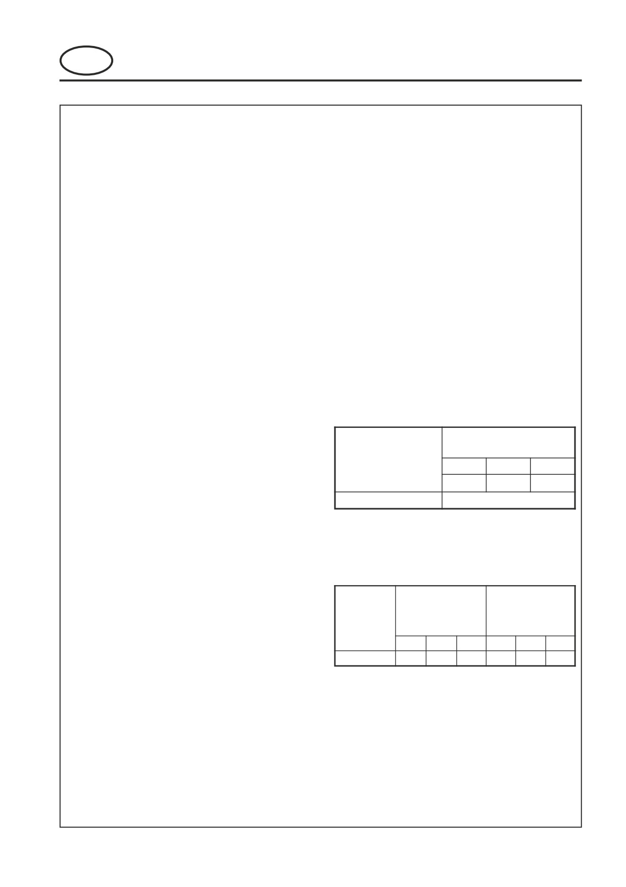
VIBRATION LEVEL
The machine was tested for whole body and hand/
Frame construction:Heavy duty formed steel chassis
arm vibration levels. The operator was seated in the
with box section frame rails.
normal operating postion with both hands on the
Cutting unit drive:
Fixed displacement hydraulic
steering mechanism. The engine was running and
motors coupled to cutting means
the cutting device was rotating with the machine
through drive belt.
stationary.
Transmission:
Full time 4-wheel drive. Direct
coupled variable displacement
Standard ISO 5349: 1986 Mechanical vibration.
pump to direct coupled 280cc
Guidelines for the measurement and the
(17.1 cu in) front, 237cc (14.5 cu
Max LH or RH
in) rear wheel motors.
FRONTLINE 960
Accelerations m/s2
Speeds:
SeriesLQ
Cutting:
0 - 12km/h (0 - 7.5 mph)
Hand / Arm Acceleration
XAeq
Y Aeq
Z Aeq
leve l
FORWARD
0.6
4
0..33
0.19
Transport:
0 - 22km/h (0 - 13.7mph)
Dominant Value
0.64
FORWARD
Reverse:
0 - 12km/h (0 - 7.5 mph)
Steering:
Hydrostatic power steering, with
assessment of human exposure to hand-transmitted
adjustable tilt steering wheel.
vibration.
Tyres:
Front -
Front - 24 x 13 - 12 4 ply rating
Standard ISO 2631-1: 1985 Evaluation of human
turf
Rear -
Rear - 20 x 10.00 - 8 6 ply rating
FRONTLIN E
turf
960
Floor Locatio n
Seat Location
SeriesLQ
Pressures:
Front tyres 20 p.s.i. (1.4 kg/cm2 )
Accelerations m/s2
Accelerations m/s2
Whole Bod y
Rear tyres 14 p.s.i. (1 kg/cm2 )
Acceleratio n
leve l
Ground pressure:
14p.s.i. (1 kg/cm2 )
x
y
z
x
y
z
Mea n
0.06
0.05
0.18
0.05
0.05
0.02
Brakes, Service:
Positive hydrostatic braking.
Parking:
Fail safe, Oil immersed wet disc
exposure to whole body vibration -- Part 1: General
brakes.
requirements.
Fuel Tank
Capacity:
45.4 litres (10 Imp. galls) 12 US
4.5
SLOPES
galls
Hydraulic Tank
DO NOT USE ON SLOPES GREATER THAN 15°
Capacity:
18.8 litres (4.14 Imp. galls) 5 US
The slope 15° was calculated using static stability
galls
measurements according to the requirements of
EN 836.
Battery:
Exide 065
GB-7
4
SPECIFICATIONS
FRONTLINE 960 Series: LQ
MAINTENANCE AND PARTS MANUAL
GB
4.6
RECOMMENDED LUBRICANTS
Engine oil:
Should be to MIL-L-2104C or to
A.P.I. Classification SE/SF/SG
grades. [10W-30]
Hydraulic Oil:
Shell Tellus 46
Grease:
Shell Darina R2, or equivilant.
4.7
CUTTING PERFORMANCE (AREA)
9'8" Model
3.2 hectares/hr. at 12 km/hr. ( 7.9 acres/hr at 7.5
mph)
10'7" Model
3.5 hectares/hr. at 12 km/hr. ( 8.65 acres/hr at 7.5
mph)
10% allowance is included for normal overlaps and
turning at the end of each cut.
4.8
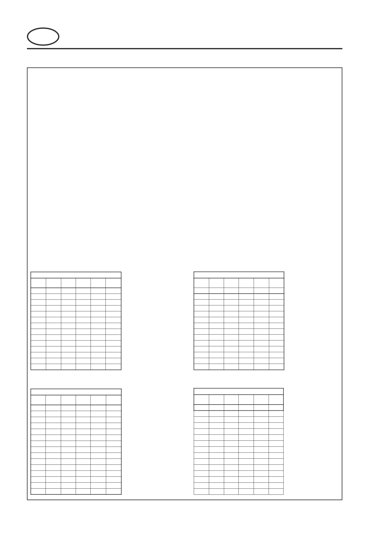
TORQUES
FINE PITCH METRIC THREAD S
CORSE PITCH METRIC THREAD S
i
GRAD E
GRAD E
GRAD E
GRAD E
GRAD E
i
GRAD E
GRAD E
GRAD E
GRAD E
GRAD E
(mm
)
1
1
(mm
)
1
1
(Nm
)
(Nm)
(Nm)
(Nm)
(Nm)
(Nm
)
(Nm)
(Nm)
(Nm)
(Nm)
6
0
0
0
0
0
6
5
6
12
17
21
8
12
16
32
45
54
8
11
15
30
42
51
10
24
31
63
88
106
10
22
30
59
84
100
12
42
57
113
159
191
12
39
52
104
146
175
14
67
90
179
252
302
14
62
82
165
232
278
16
103
137
274
385
462
16
96
129
257
362
434
20
209
279
557
783
940
20
188
251
502
706
847
22
281
375
750
1055
1266
22
256
341
683
960
1152
24
354
472
944
1327
1593
24
325
434
868
1220
1464
27
514
686
1371
1928
2314
27
476
635
1269
1785
2142
30
715
954
1908
2683
3219
30
646
862
1723
2424
2908
33
964
1286
2572
3616
4340
33
822
1097
2193
3084
3701
36
1196
1594
3189
4484
5381
36
1129
1506
3012
4235
5082
UNF THREAD S
UNC THREAD S
GRAD E
GRAD E
GRAD E
GRAD E
GRAD E
GRAD E
GRAD E
GRAD E
GRAD E
GRAD E
Dia (in)
Dia (in)
A
S
T
V
X
A
S
T
V
X
(lbf.
ft
)
(lbf.
t
(lbf.
t
(lbf.
t
(lbf.
t
(lbf.
ft
)
(lbf.
t
(lbf.
t
(lbf.
t
(lbf.
t
/
1
1
1
1
/
1
1
5/
16
2
2
2
3
5/
16
7
1
2
2
3
/
1
3
4
5
6
/
1
3
3
4
5
7/
16
2
5
6
8
9
7/
16
1
5
5
7
8
/
3
9
9
125
152
/
3
8
88
112
135
9/
16
4
131
141
179
217
9/
16
4
117
127
161
195
/
6
183
197
250
303
/
5
162
175
222
269
/
118
319
344
437
529
/
106
288
310
394
477
/
188
509
550
697
845
/
171
464
500
635
769
1
279
757
817
1036
1255
1
256
695
749
950
1152
1
/
405
1099
1186
1504
1823
1
/
363
984
1062
1347
1632
1
/
563
1529
1650
2093
2535
1
/
511
1387
1497
1899
2300
1
/
759
2061
2224
2821
3418
1
/
670
1820
1963
2490
3017
1
/
996
2703
2917
3699
4482
1
/
889
2414
2605
3303
4002
GB-8
5
LUBRICATION AND MAINTENANCE
FRONTLINE 960 Series: LQ
MAINTENANCE AND PARTS MANUAL
GB
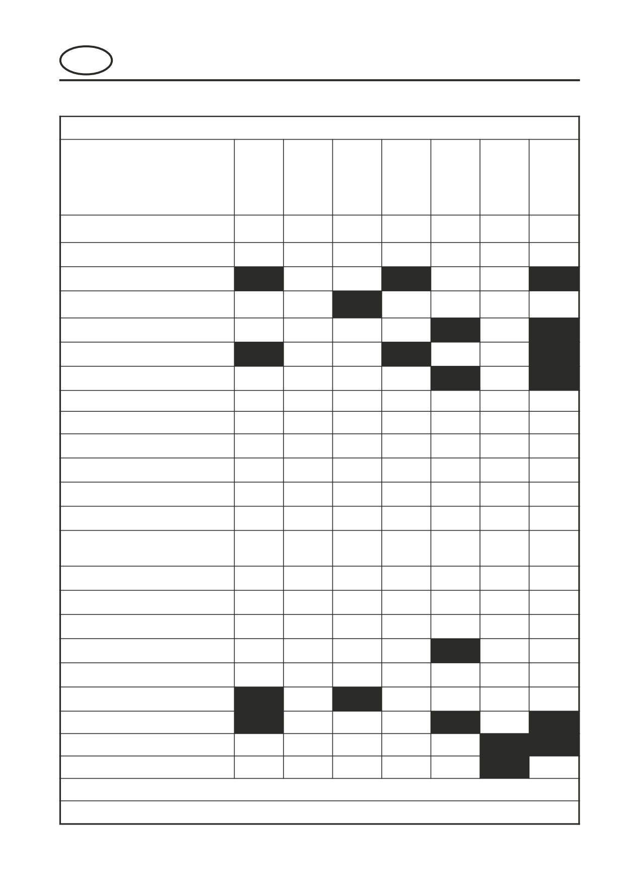
LUBRICATION AND MAINTENANCE CHART
B lack bullet points are operator checks and w hite bullet points are w orkshop maintenance procedure s
Firs t
Every
Every
Every
End
Daily
Every
5
0
250
400
600
of
50 hours
hours
hours
hours
hours
Season
ENGINE (Service As Per Engine
Manual)
C heck/Top-up Oil Leve l
z
C hange Oil
z
z
z
C lean Air Filter Element & Particle
z
Collector
C hange Air Filter Elemen t
z
z
C hange Oil Filter C artridg e
z
z
z
z
Replace Fuel Filters
z
z
MACHIN E
C heck Interlock Syste m
z
C heck/Top-up C oolant Leve l
z
C heck Tyre Pressure
z
C heck/Top-up Hydraulic Fluid
z
C heck/C lean & Remove Grass fro m
E ngine C ompartment, Pum p
z
Conpartment, Bug Screen & Radiator
C heck Nuts & Bolts For Tightnes s
z
C heck Hydraulic Fittings For Tightnes s
z
C heck Rear Wheel Toe-in
z
C heck Battery C onditio n
z
C heck Fan Belt Tensio n
z
z
C hange Hydraulic Oil & Filte r
z
z
z
z
Drain & Clean Fuel Tank
z
z
Drain & Flush Cooling System
z
*Service more often in dirty condition s
Lubricate the Grease Fittings with Shell Darina R2 grease weekly (SEE CHAR
T
)
GB-9
5
LUBRICATION AND MAINTENANCE
FRONTLINE 960 Series: LQ
MAINTENANCE AND PARTS MANUAL
GB
LUBRICATION
Fig.3
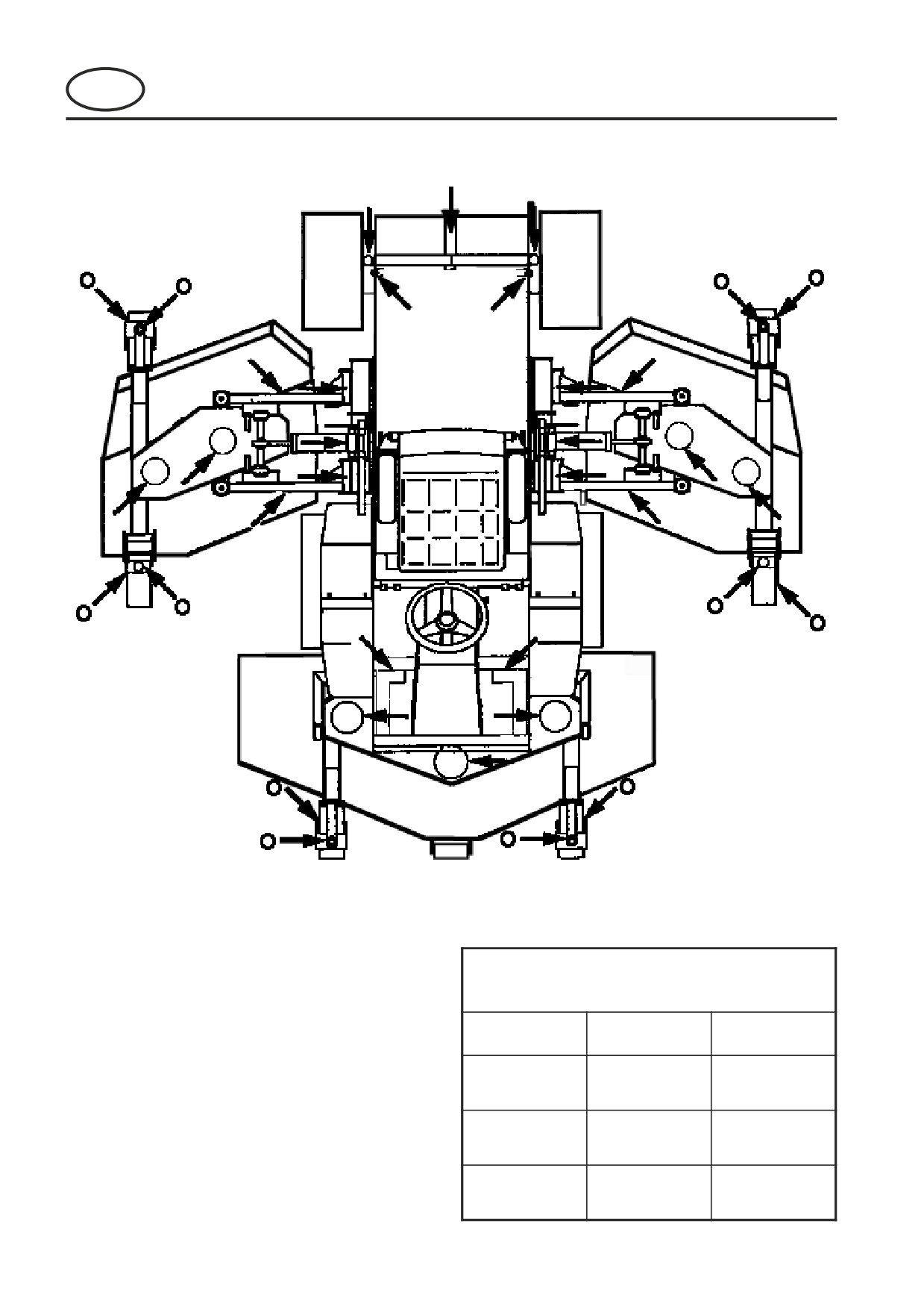
z Lubricate every 40 working hours at arrows
FLUID REQUIREMENT S
QUANTITY
TYPE
ENGINE OIL
1
10W 30 (SE/SF/SG)
(with filter)
HYDRAULIC OIL
3
ShellT
l
(with filter)
RADIATO R
5.5L
t
50% ANTI-FREEZE
COOLAN T
GB-10
5
LUBRICATION AND MAINTENANCE
FRONTLINE 960 Series: LQ
MAINTENANCE AND PARTS MANUAL
GB
LUBRICATION
5.1
ENGINE: First 50 working hours and
every 250 working hours.
Change Engine Oil.
(a)
Warm up the engine first and then shut it
off. Remove oil drain plug from the bottom
of the crankcase and wipe it off.
(b)
Replace the drain plug and fill engine with
10.6 litres of oil(with filter).
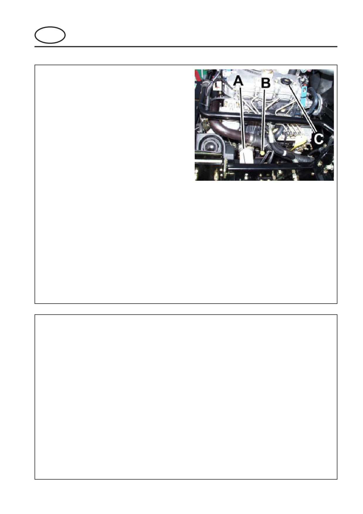
Fig.1
A Oil Fill, B Dipstick, C Oil fill
Fig.1
Change Engine Oil Filter (A)
(a)
Remove single-unit cartridge (A)
(b)
Clean area on crankcase.
(c)
Apply thin coat of oil to cartridge gasket
before installing.
(d)
Tighten filter by hand only.
(e)
Check for oil leaks around the cartridge
gasket after engine is started.
5.2
MACHINE: Lubricate the following
points. Weekly or every 40 working
hours.
1. Lubricate the following with Shell Darina R2
grease. (Fig.3)
(a)
Lift arm pivots.
(b)
Rear Axle centre pivot.
(c)
Steering rams-inner pivots.
(d)
Steering ram rod end.
(e)
Steering Track Rod, Rod End.
(f)
Lift arm yoke pivots.
(g)
Belt pulleys.
(h)
Deck Castor wheels
GB-11
5
LUBRICATION AND MAINTENANCE
FRONTLINE 960 Series: LQ
MAINTENANCE AND PARTS MANUAL
GB
LUBRICATION
5.3
MACHINE: Every400 Working Hours.
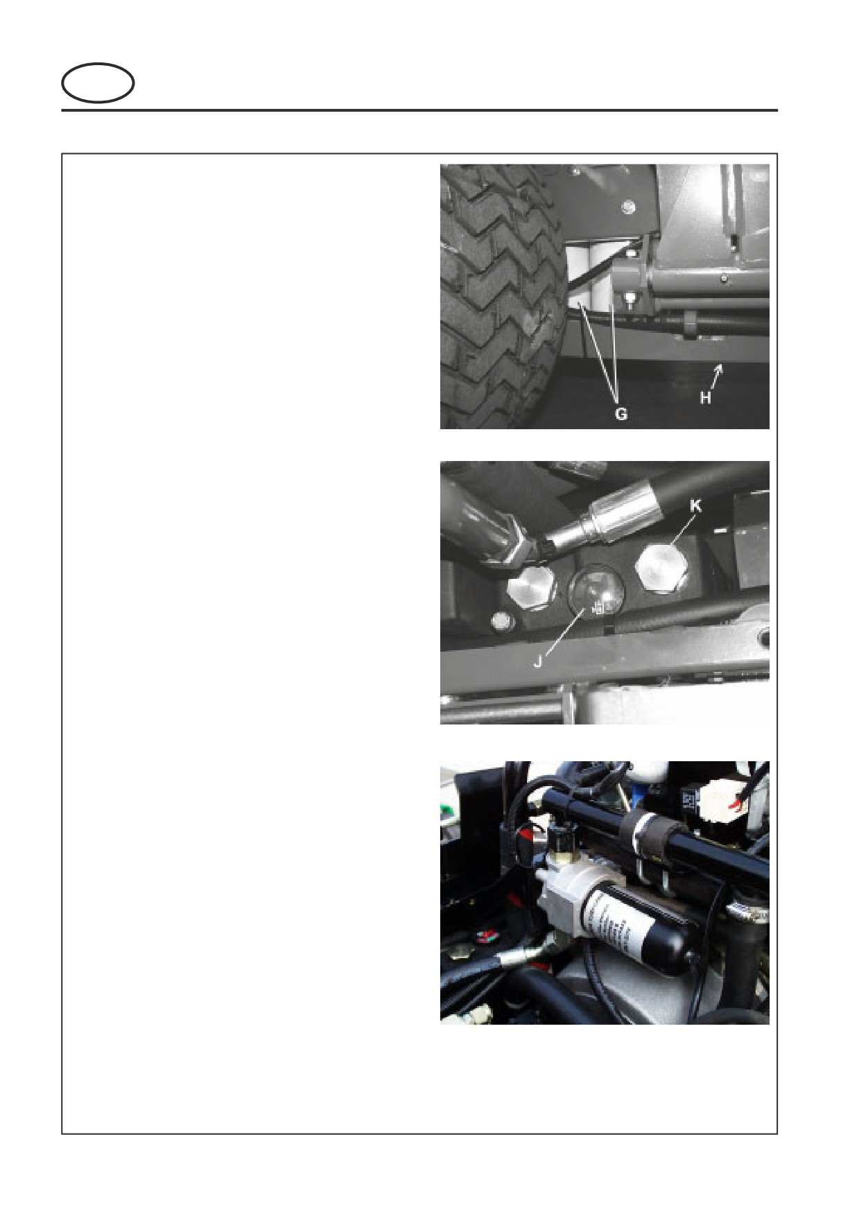
1. Drain Oil reservoir by removing drain plug H on
bottom of hydraulic oil reservoir.
2. Ensure that plug is clean and reinstall in tank.
3. Unscrew both filter elements G and discard.
4. Clean the rubber seal through which the filter
elements pass.
5. Apply a thin film of oil to the seals of the new
filters and install.
6. Remove plug K and add the recommended oil
Fig 5) until the indicator on the oil level gauge J
is centered in the green area of the gauge. Avoid
operation in either red zone as insufficient oil
could damage hydraulic components. Too much
Fig.4
oil could lead to oil overflowing the reservoir as it
heats up.
7. Reinstall plug K.
8. Start the tractor and allow to run at 1/4 throttle
for approximately 5 minutes.
9. Allow oil to cool and recheck the oil level and
adjust as required.
Hydraulic oil type requirements:
Shell Tellus 46
Fig.5
Change Hydraulic Oil Filter (CHARGE) (Fig.6)
1.
Wipe filter canister and housing to remove any dirt
present.
2.
Place a suitable drip tray under the filter.
3.
Un-screw filter canister and remove the filter
element and dispose of safely.
4.
Replace with new filter element.
5.
Coat the top outside lip of the filter canister with a
thin film of oil and refit the filter canister.
6.
Filter should be replaced before refilling hydraulic
tank.
Fig.6
GB-12
5
LUBRICATION AND MAINTENANCE
FRONTLINE 960 Series: LQ
MAINTENANCE AND PARTS MANUAL
GB
LUBRICATION
5.4
HYDRAULIC TEST PORTS
If any problems are experienced with the hydraulic
system, service ports are provided to enable
pressures to be checked.
All tests, unless stated otherwise, should be carried
out with the hydraulic oil at normal working
temperature.
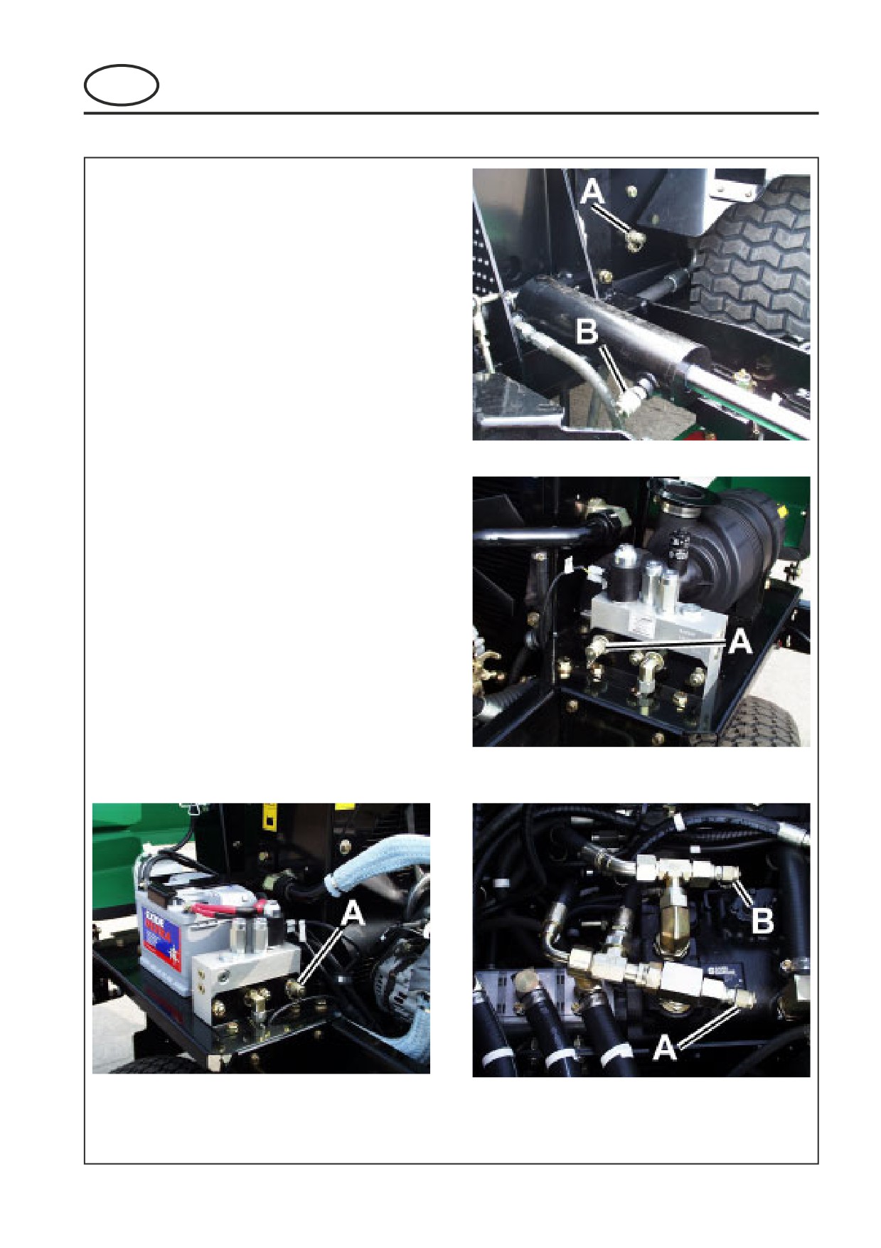
TEST PORTS (Fig.7,8,9):
1.
Front Cutter Deck Pressure: 220 bar
(3200 psi). (A(Fig.7)).
Lift Pressure : 63.5 bar (920 psi).
(B(Fig.7)).
2.
RH & LH Cutter Deck Pressure: 210 bar
Fig.7
(3045 psi). (A(Fig.8 & 9)).
3.
FWD Transmission Pressure : 250 bar
(3625 psi). (A(Fig.10)).
4.
REV Transmission Pressure : 210 bar
(3045 psi). (B (Fig.10)).
5.
Charge Pressure : 15.8 - 19.3 bar
(230-280 psi). (Either A or B(Fig.10))
NOTE: Any servicing of the hydraulic system
must be carried out by trained service
personnel.
Fig.8
Fig.9
Fig.10
GB-13
5
LUBRICATION AND MAINTENANCE
FRONTLINE 960 Series: LQ
MAINTENANCE AND PARTS MANUAL
GB
MAINTENANCE
5.5
ENGINE MAINTENANCE: Every 250 hrs
Fuel System:
Use Diesel fuel No.2-D (ASTM D975)
See engine manufacturer's manual for additional
information.
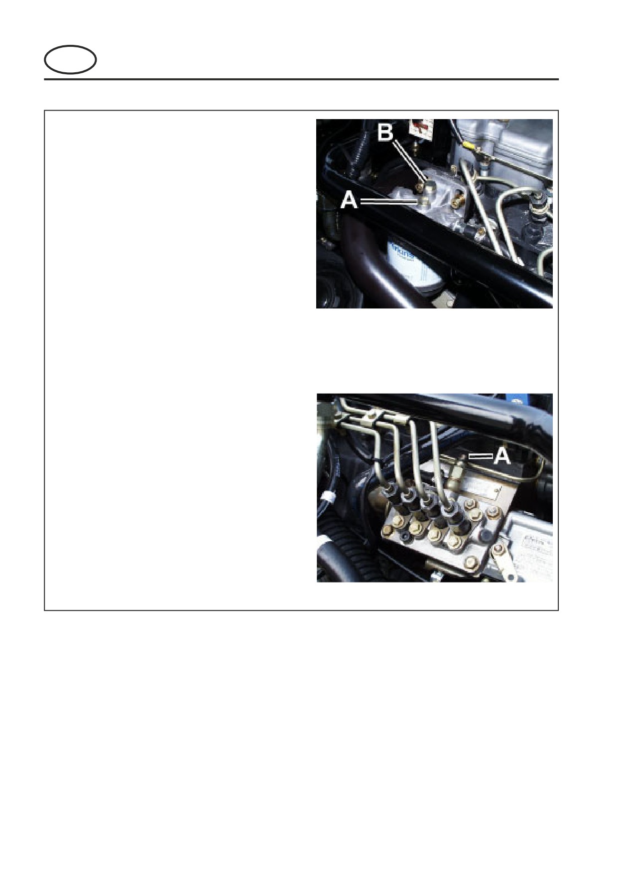
Changing fuel filter (Fig.10)
1.
Unscrew filter screw (A) from filter head.
2.
Bleed air from system as described in
section 5.5
Fig.10
Bleeding air from fuel system
1.
Turn the ignition switch to the ON position
(dont start engine)
2.
Open air vent A onto top of fuel filter to
allow air to escape.(Fig.10)
3.
Retighten air vent.
4.
Open air vent (A) on side of injector pump
to allow air to escape.(Fig.11)
5.
Retighten air vent
6.
Turn ignition to OFF.
Fig.11
GB-14
5
LUBRICATION AND MAINTENANCE
FRONTLINE 960 Series: LQ
MAINTENANCE AND PARTS MANUAL
GB
MAINTENANCE
5.6
ENGINE MAINTENANCE: Every 400 hrs
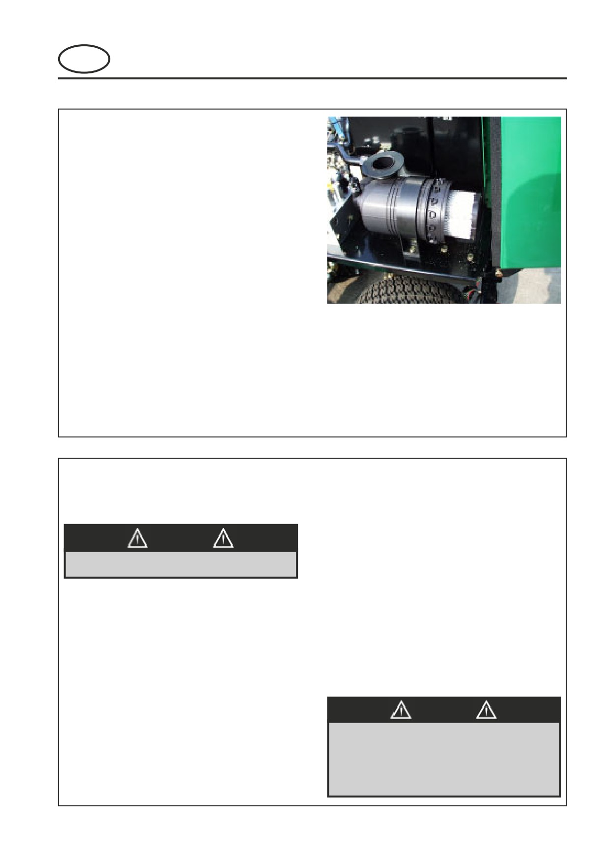
Cleaning the air filter.
To remove the cover, pull the yellow finger on the
cover towards you. Take hold of the cover firmly and
twist it to the left. Pull the cover towards you to
open the housing. Remove old filter gently , then
clean inside of the housing carefully.
Remove loose dirt from element with compressed air
working from the clean to dirty side, using
compressed air max 6 bar, with nozzle 5cm from
element. The element should be cleaned no more
than 6 times. In any case we recommend replacing
the main element once a year irrespective of how
many times it has been cleaned.
Fig.12
To close the cover reverse operation.
NOTE: Extensive damage to engine can result
from an inadequate air supply.
5.7
MACHINE MAINTENANCE
bearing seals and cause premature bearing failure.
Storage
•
Store petrol or diesel fuel in an approved
Battery.
container in a cool dry place.
Keep fluid levels above battery plates.
•
Keep the machine and fuel containers in a
locked storage place to prevent tampering
WARNING
and to keep children from playing with
them.
Wear eye protection when servicing battery.
•
Do not store fuel or petrol/diesel fuel
powered equipment in any closed area
where heating appliances, pilot lights or
Other Regular Service.
any sort of open flame is present.
•
Verify proper operation of safety interlock
•
Before storing, allow the engine to cool,
switches (Neutral switch, Seat switch,
and drain fuel completely from fuel tanks
etc.)
and containers.
•
Ensure nuts and bolts remain tight.
•
Maximum safety and best mowing results
•
Keep tyre pressure at 1kg/cm2 (14psi).
can only be expected if the mower is
•
Follow the engine manufacturer’s
maintained and operated properly.
maintenance recommendations.
•
If a label becomes worn or removed, see
WARNING
the LABELS section of this manual or the
tractor Parts Manual for replacement
Battery posts, terminals and related
information.
accessories contain lead and lead
compounds.
NOTE: When washing machine with pressure spray
washers or steam cleaners, avoid washing bearing
WASH HANDS AFTER HANDLING
areas because cleaning solutions might penetrate
GB-15
5
LUBRICATION AND MAINTENANCE
FRONTLINE 960 Series: LQ
MAINTENANCE AND PARTS MANUAL
GB
MAINTENANCE
5.8
END OF SEASON or when required
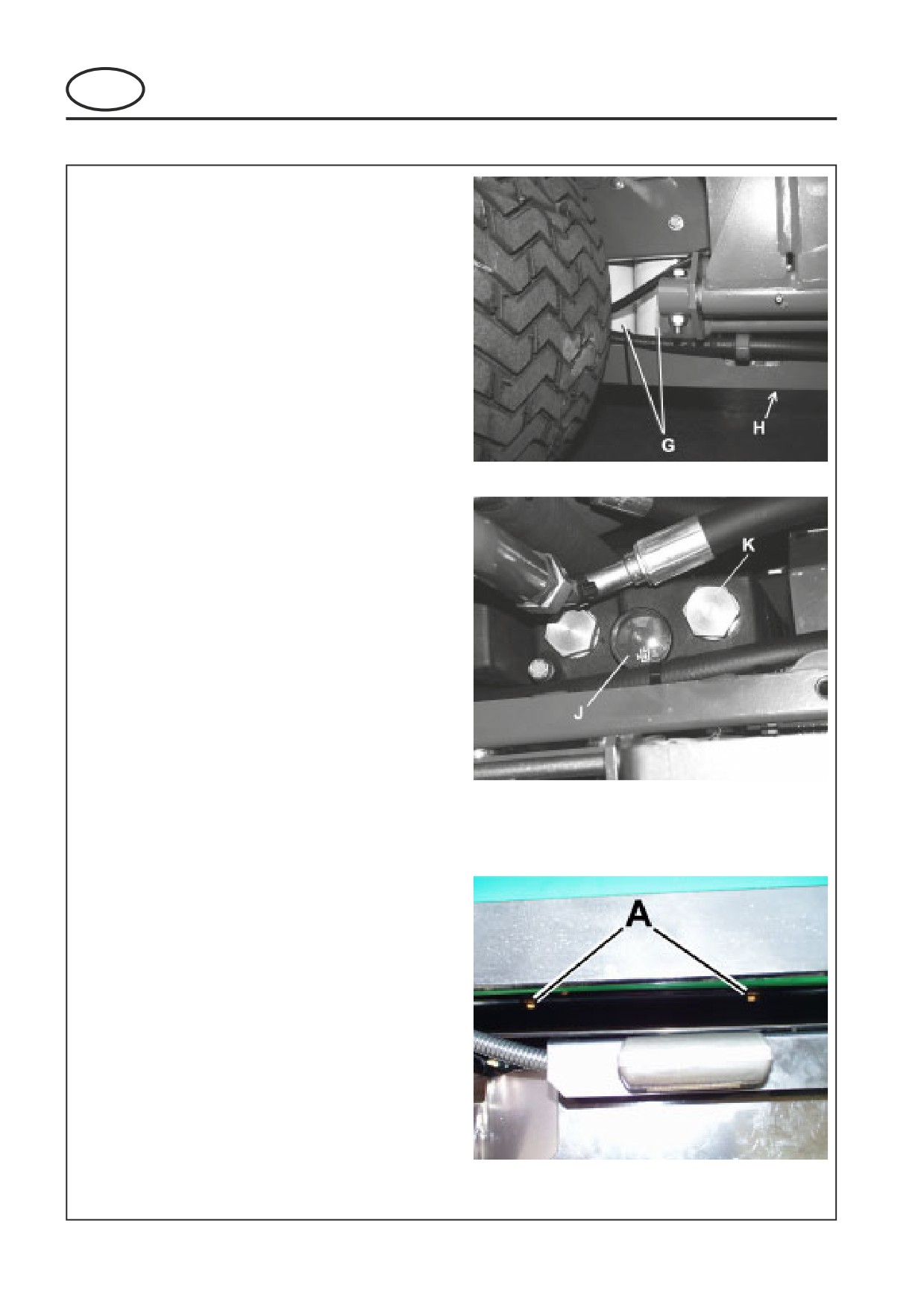
1. Drain Oil reservoir by removing drain plug H on
bottom of hydraulic oil reservoir.
2. Ensure that plug is clean and reinstall in tank.
3. Unscrew both filter elements G and discard.
4. Clean the rubber seal through which the filter
elements pass.
5. Apply a thin film of oil to the seals of the new
filters and install.
6. Remove plug K and add the recommended oil
Fig 5) until the indicator on the oil level gauge J
is centered in the green area of the gauge. Avoid
operation in either red zone as insufficient oil
could damage hydraulic components. Too much
oil could lead to oil overflowing the reservoir as it
Fig.13
heats up.
7. Reinstall plug K.
8. Start the tractor and allow to run at 1/4 throttle
for approximately 5 minutes.
9. Allow oil to cool and recheck the oil level and
adjust as required.
Hydraulic oil type requirements:
Shell Tellus 46
Change Hydraulic Oil Filter(Fig.6 Ref to pg 12)
1.
Wipe filter canister and housing to remove any dirt
present.
2.
Place a suitable drip tray under the filter.
3.
Un-screw filter canister and remove the filter
element and dispose of safely.
Fig.14
4.
Replace with new filter element.
5.
Coat the top outside lip of the filter canister with a
thin film of oil and refit the filter canister.
6.
Filter should be replaced before refilling hydraulic
tank.
Change Coolant.
1.
Completely drain the cooling water from
the radiator and flush the cooling system
with flushing detergent. Drainplugs A.
2.
Check for leaks or loose connections at
the radiator, cylinder head gasket, etc.
3.
Mix antifreeze coolant and water at the
specified ratio before pouring into the
engine.
Note:
When topping up the cooling system fill
Fig.15
with 50/50 solution.
GB-16
6
ADJUSTMENTS
FRONTLINE 960 Series: LQ
MAINTENANCE AND PARTS MANUAL
GB
ADJUSTMENTS
6.1
SPEED LIMITER
NOTE: Textron Turf Care cannot be held responsible
The transport and mow speeds are factory set and
for loss of performance or machine damage if these
should not need altering.
speeds are adjusted outside the speeds shown in the
machine specification.
6.2
REAR WHEEL TOE-IN
The rear wheels should have 1/8" (3.2mm) toe-in
from the front of the wheel to the back of the wheel.
Adjust as follows:
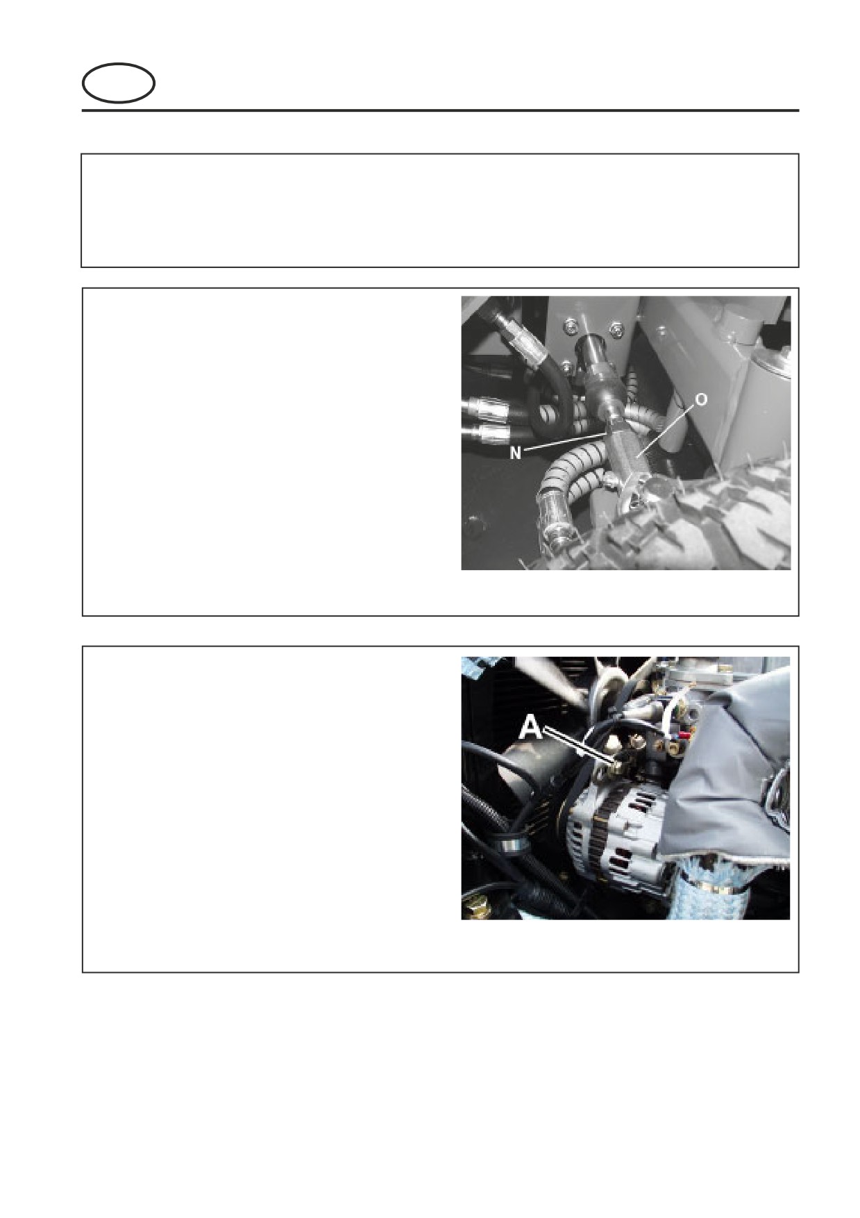
1. Loosen locknuts N at balljoints near both rear
wheels.
2. Rotate the tie rod O until wheels are correctly
positioned. Adjust both tie rods an equal
amount.
3. Re-tighten locknuts. The tires should then be 1/
8" closer at the front than the rear.
Fig.16
6.3
ALTERNATOR
The fan belt is adjusted so that it can be deflected
5mm (0.2in) with a force of 5 kg (11 lbs) applied
midway between the crankshaft and alternator
pulley. (Fig.17) To adjust:
1.
Loosen alternator bolts A.
2.
Move the alternator to tighten or loosen fan
belt.
3.
Tighten bolts A.
Check belt tension and condition of belt every 250
hours.
Fig.17
GB-17
7
CUTTER DECK ADJUSTMENTS
FRONTLINE 960 Series: LQ
MAINTENANCE AND PARTS MANUAL
GB
CUTTER DECK ADJUSTMENTS
7.1
CUTTER DECK BELT TENSION
Check all belts regularly during the first 5, 10 and 15
hours of operation, and then after every 50 hours of
operation. If necessary adjust as follows:
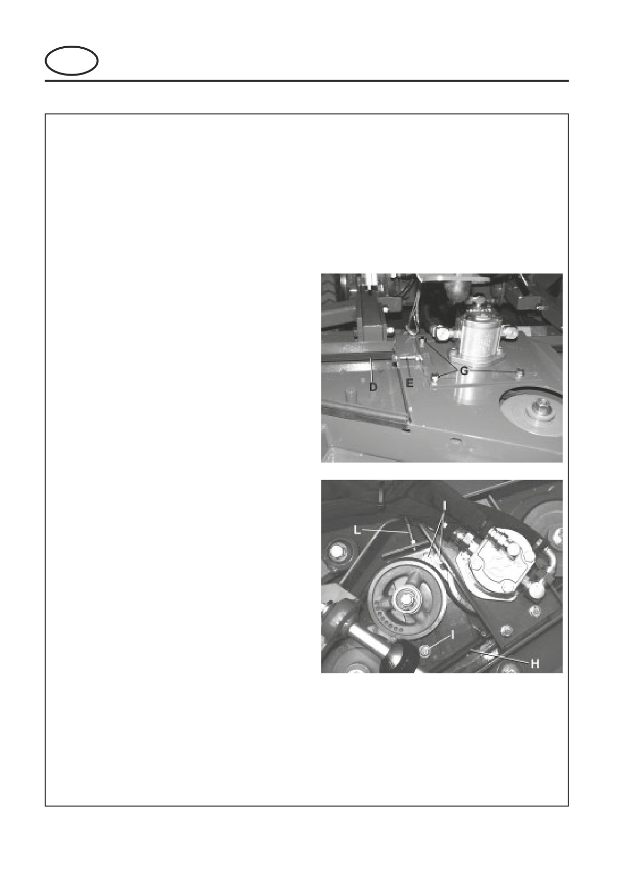
CENTER DECK
1. Adjust belt tension to 1/2” (13 mm) deflection at
10 lbs (5 kg) force at the middle of the long rear
span D. If necessary, adjust as follows:
2. Loosen locking nut on adjustment bolt E.
3. Loosen (4) bolts G fastening the motor mounting
plate to the cutter deck (3 visible in photo).
4. Turn adjustment bolt E until proper tension is
obtained.
5. Retighten (4) bolts G and lock nut on adjust-
ment bolt E.
WING DECKS
1. Adjust belt tension to 3/8” (10 mm) deflection at
10 lbs (5 kg) force at the middle of the long rear
span H. If necessary, adjust as follows:
2. Loosen locking nut on adjustment bolt L.
3. Loosen two bolts I fastening the idler plate to
the cutter deck.
4. Turn adjustment bolt L until proper tension is
obtained.
5. Retighten bolts I and lock nut on adjustment
bolt L.
GB-18
7
CUTTER DECK ADJUSTMENTS
FRONTLINE 960 Series: LQ
MAINTENANCE AND PARTS MANUAL
GB
CUTTER DECK ADJUSTMENTS
7.2
BLADE SHARPENING & REMOVAL
When required, the cutter blades may be sharpened
either by filing or grinding. It is essential that the
balance of the blades are maintained.
NOTE: Always replace blades with original Ran-
somes blades, do not use another manufacturers
blades.
- Service the blades with the tractor turned off,
and the decks securely supported.
- Do not overheat or weaken the blades.
- If blade becomes cracked or bent, replace with a
new blade to ensure safe operation
- f lift portion of blade is worn thin replace with a
new blade to ensure safe operation
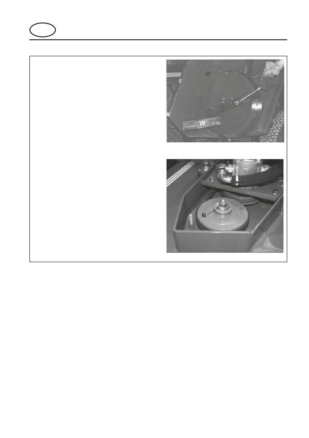
- Place block of wood W between blade and deck
baffle to prevent blade from turning during
removal
- Keep hands clear of rotating blades
Removing Blades
1. Remove the nut N from the top of the blade
spindle bolt
2. Remove the blade spindle bolt with the washer
and blade.
3. Replace the blade, washer and blade spindle
bolt.
GB-19

8
TROUBLESHOOTING
FRONTLINE 960 Series: LQ
MAINTENANCE AND PARTS MANUAL
GB
8.1
GENERAL
The troubleshootijng chart below lists basic problems that may occur during start-up and operation. For more
detailed information regarding the hydraulic and electrical systems contact your area Jacobsen Distributor.
Symptom s
Possible Causes
Action
Section
1. Reset ignition switch and alow glow plug
t
1. Glow Plug has not
t
time out before cranking engine.
2. Battery
l
2.
I
defective
connections.
3. Fuel tank empty or
f
3. Fill tank withfreshfuel. Change
f
contaminated .
from
l
Engine will not start.
4. Blown Fuse.
4. Replace Fuse.
5. Defective Starter Relay.
5. Test and replace relay if neccesary.
6.Forward/Reverse pedal
l
6. Ensure Forward/Reverse pedal neutral
l
depressed.
not depressed .
7. Mow switch set
t
7. Set mow switchto off.
1. Fuel tank empty or
f
1. Fill tank withfreshfuel. Change
f
contaminated .
from
l
Engine hard
t
2. Air Cleaner blocked or dirty
2. Check air cleaner, replace as neccesary.
or runs poorl.
3. Injectors,
f
3. Cons
l
4. Other Engine Problem
4. Consult engine
t
1. Fuel
t
1. Fill withfreshfuel and bleed
l
Engine Stops.
2.
I
2. Set mow switchto off. Ensure
f
leaving operators seat
neutral
l
1.
I
1. Coolant level
l
required
Engine Overheating.
2. Radiator air intake restricted
2. Clean wire mesh guard at radiator.
3. Waterpump/alternator belt or
3. Inspect waterpump/alternator belt and
f
fan belt
l
T
ighten if neccesary.
1. Loose or corroded battery
1. Inspect terminals, clean and
t
terminals
required
2. Low electrolyte level
i
Battery not holding
2. Refill battery with diste
l
battery.
charge. Battery
l
on.
3. Alternator belt
l
3.
I
broken.
neccesary.
4. Alternator defective
4. See engine manual.
1. Cylinder
t
1. Inspect cylinder
t
adjusted properl.
2. Engine speed too
l
2. Check engine speed, run engine at full throt
l
C
l
3. C
l
3. Adjust cylinder speed
f
unevenly. Poo r
for
t
quality of cut.
4. Cylinder direction
l
4. Set cylinder direction lever to
f
in reverse
5. Ground weight incorrect
l
5. Adjust ground weight control valve until correct
adjusted
ground weight is achieved .
GB-20
9
SCHEMATICS
FRONTLINE 960 Series: LQ
MAINTENANCE AND PARTS MANUAL
GB
9.1
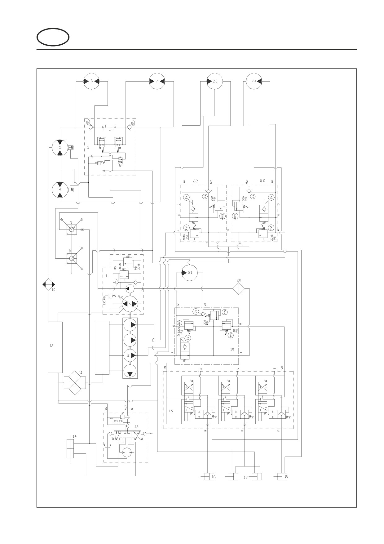
HYDRAULIC CIRCUIT
1. Transmission Pump
2. 4 Section Pump
3. Transmission Valve
4. RF Wheel Motor
5. LF Wheel Motor
6. LR Wheel Motor
7. RR Wheel Motor
8. Brake Valve
9. Aux Brake Valve
10. Oil Cooler
11. Filter Head
12. Reservoir/Tank
13. Steer Valve
14. Steer Ram
15. Lift Valve
16. RH Lift Cylinder
17. Centre Lift Cyl's
18. LH Lift Cylinder
19. Front Cutter Deck Valve
20. Charge Filter
21. Front Cutter Deck Motor
22. Wing Deck Valves
23. LH Cutter Motor
24. RH Cutter Motor
25. Inlet Manifold
GB-21
9
SCHEMATICS
FRONTLINE 960 Series: LQ
MAINTENANCE AND PARTS MANUAL
GB
9.2
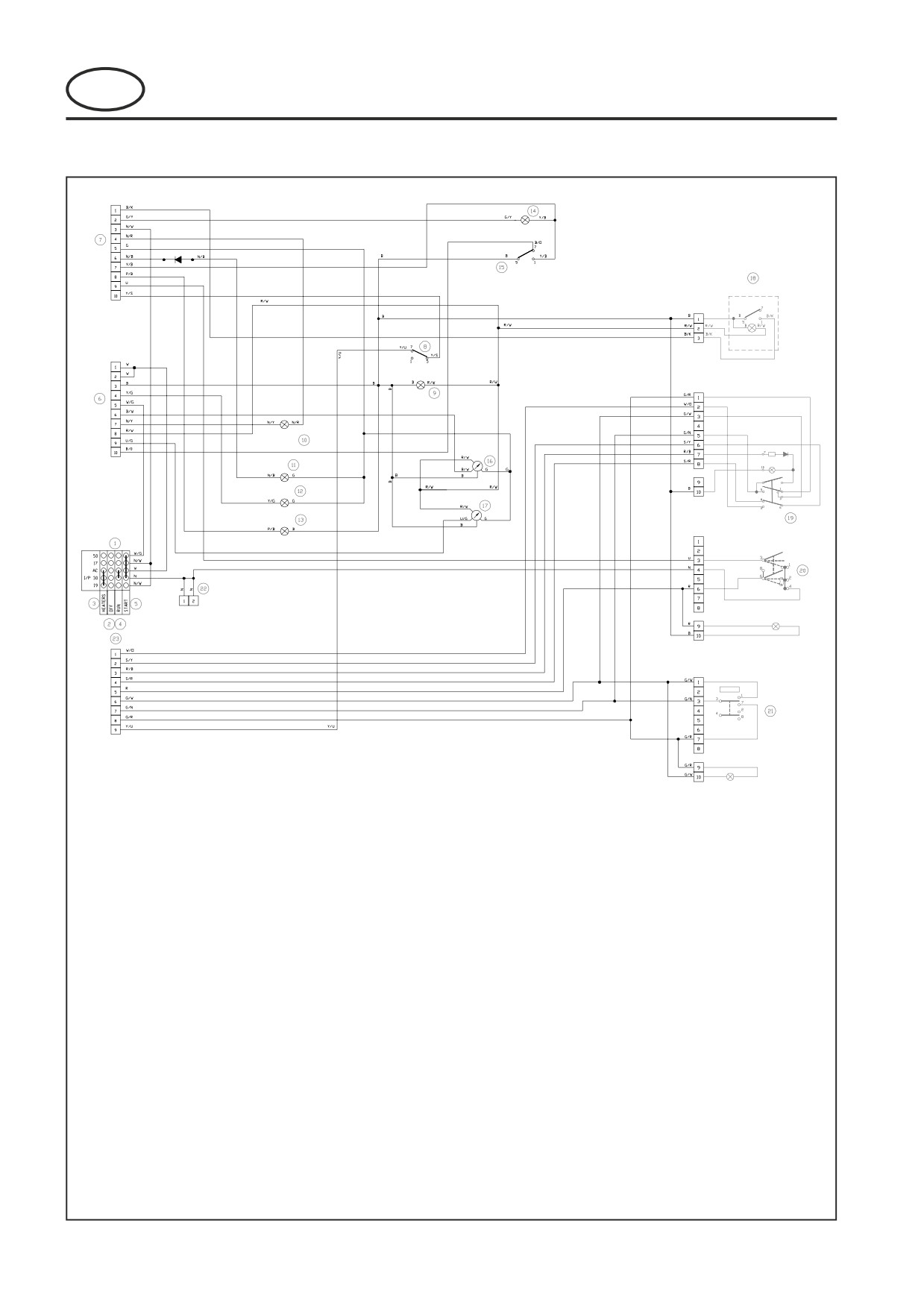
ELECTRICAL CIRCUIT INSTRUMENT
KEY TO WIRING DIAGRAM
1
Key Switch
22
Split to Main Harness No.3
2
OFFPosition
23
Split to Main Harness No.4
3
HEATER Position
4
RUN Position
5
START Position
CABLE COLOUR CODE
6
Split to Main Harness No.2
7
Split to Main Harness No.1
R
Red
8
2WD Switch
G
Green
9
2WD Lamp
O
Orange
10
Glow Indicator Lamp
S
Grey
11
Battery Lamp
B
Black
12
Oil Temperature Lamp
W
White
13
Oil Pressure Lamp
K
Pink
14
Cutting Deck Switch Lamp
P
Violet
15
Cutting Deck Switch
Y
Yellow
16
Fuel Guage
U
Blue
17
Temperature Guage
N
Brown
18
Beacon Switch (Optional)
LG
Light Green
19
Hazard Swicth
20
Lights
E.G. R/W = Red/White
21
Direction Indicators
GB-22
9
SCHEMATICS
FRONTLINE 960 Series: LQ
MAINTENANCE AND PARTS MANUAL
GB
9.3
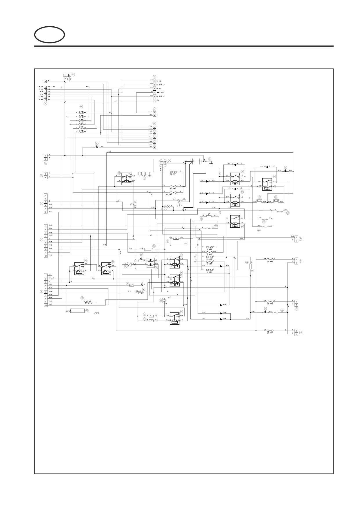
ELECTRICAL CIRCUIT MAIN
KEY TO WIRING DIAGRAM
24
Lamp Timer
41
Fuel Level Sender
64
RH Deck Kill Switch
25
Cab Supply
42
Water Temperture Sender
65
RH Cutter Deck Valve
26
Front Lamps
43
Engine Oil Pressure Switch
66
LH Cutter Deck Valve
27
Flasher Unit
44
Horn Relay
67
Centre Cutter Deck Valve
28
Fuse Holder
45
Horn
68
Seat Delay Module
29
Split to Rear Lights
46
Start Reley
69
Brake Release Engine Kill
30
Brake Lights Switch
47
Alarm Relay
70
Engine Fule Soleniod
Connection
48
Seat Switch
71
Split to Beacon
31
Split to Console No.4
49
Park Switch
72
Accessory Supply
32
Transport Deck Disable
50
Diff Lock Switch
73
Air Seat Supply
Switch
51
Fuel Pump
74
Heated Jacket Supply
33
Glow Plug Relay
52
Starter
75
Water Temp Sender
34
Glow Plugs
53
Battery
35
Alternator
56
Centre Relay
36
Relay Flasher
57
LH Deck Relay
37
Accessory Control Relay
58
Deck enable Switch
38
Accessory Relay
59
Diff Lock Valve
39
Hourmeter
60
4WD Relay
40
Switch Hydraulic Oil
61
RH Deck Relay
Tempature
62
Centre Deck Switch
63
LH Deck Kill Switch
GB-23
9
SCHEMATICS
FRONTLINE 960 Series: LQ
MAINTENANCE AND PARTS MANUAL
GB
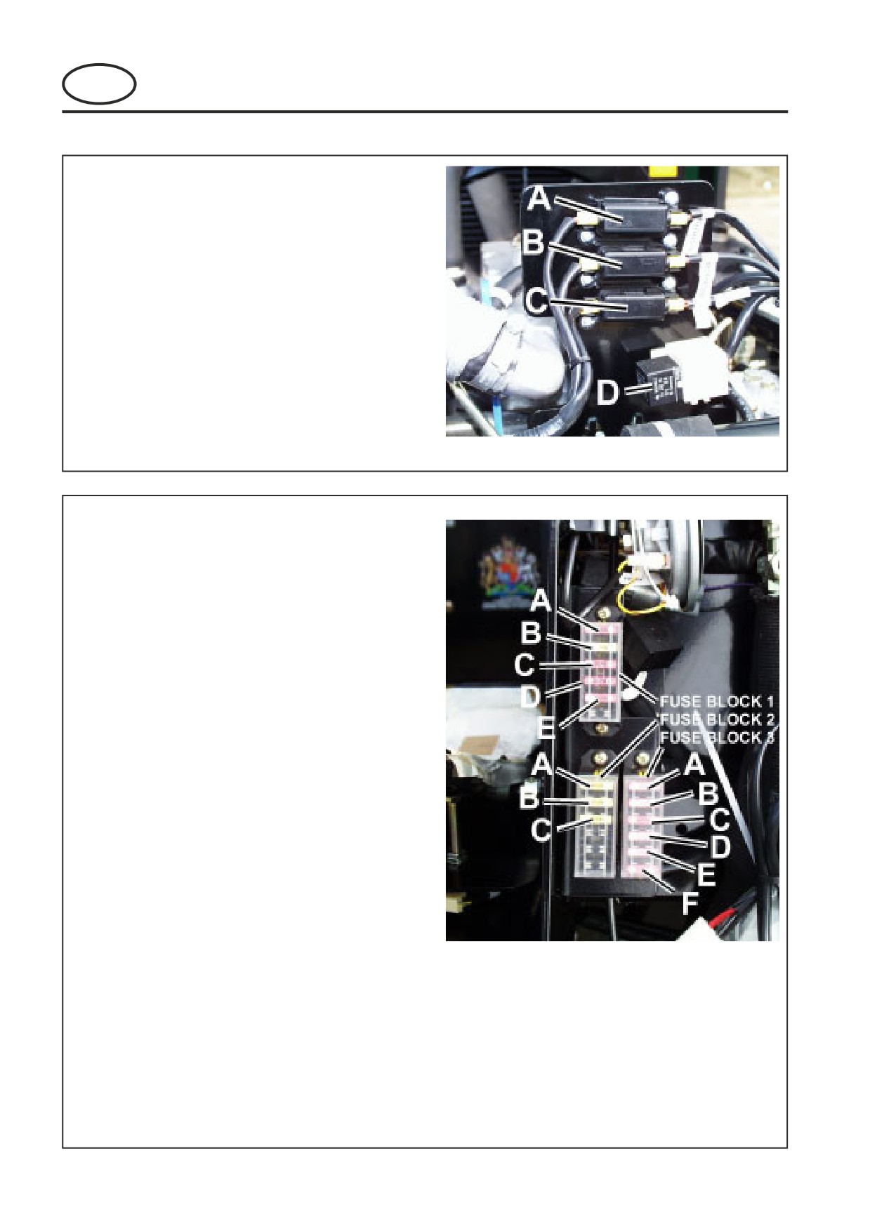
FUSE POSITIONS - MAIN FUSES
MAIN FUSES
The main fuse panel is situated under the front of
the engine bonnet .
Fuse A - 40Amp Link Fuse - System Fuse.
Fuse B - 40Amp Link Fuse - Glow Plug and
Accessory Fuse.
Fuse C - 40 Amp Cab Fuse.
Relay D - Glow Plug Relay.
SECONDARY FUSES
The secondary fuse panel is situated under the front
tower cover.
FUSE BLOCK 1
Fuse A - 10Amp - Fuel pump/Alternator.
Fuse B - 20Amp - Main Ignition.
Fuse C - 10Amp - Horn.
Fuse D - 10Amp - Glow Plug Relay.
Fuse E - 10Amp - Beacon
Fuse F - Spare.
FUSE BLOCK 2
Fuse A - 20Amp - Accessory.
Fuse B - 20Amp - Air Seat.
Fuse C - 20Amp - Heated Jacket.
Fuse D - Spare.
Fuse E - Spare.
Fuse F - Spare.
FUSE BLOCK 3
Fuse A - 10Amp - LH Headlamp.
Fuse B - 10Amp - RH Headlamp.
Fuse C - 10Amp - RH Side Lights.
Fuse D - 10Amp - LH Side Lights.
Fuse E - 10Amp - Hazards.
Fuse F - 10Amp - Indicators /Brake Lights
GB-24
9
SCHEMATICS
FRONTLINE 960 Series: LQ
MAINTENANCE AND PARTS MANUAL
GB
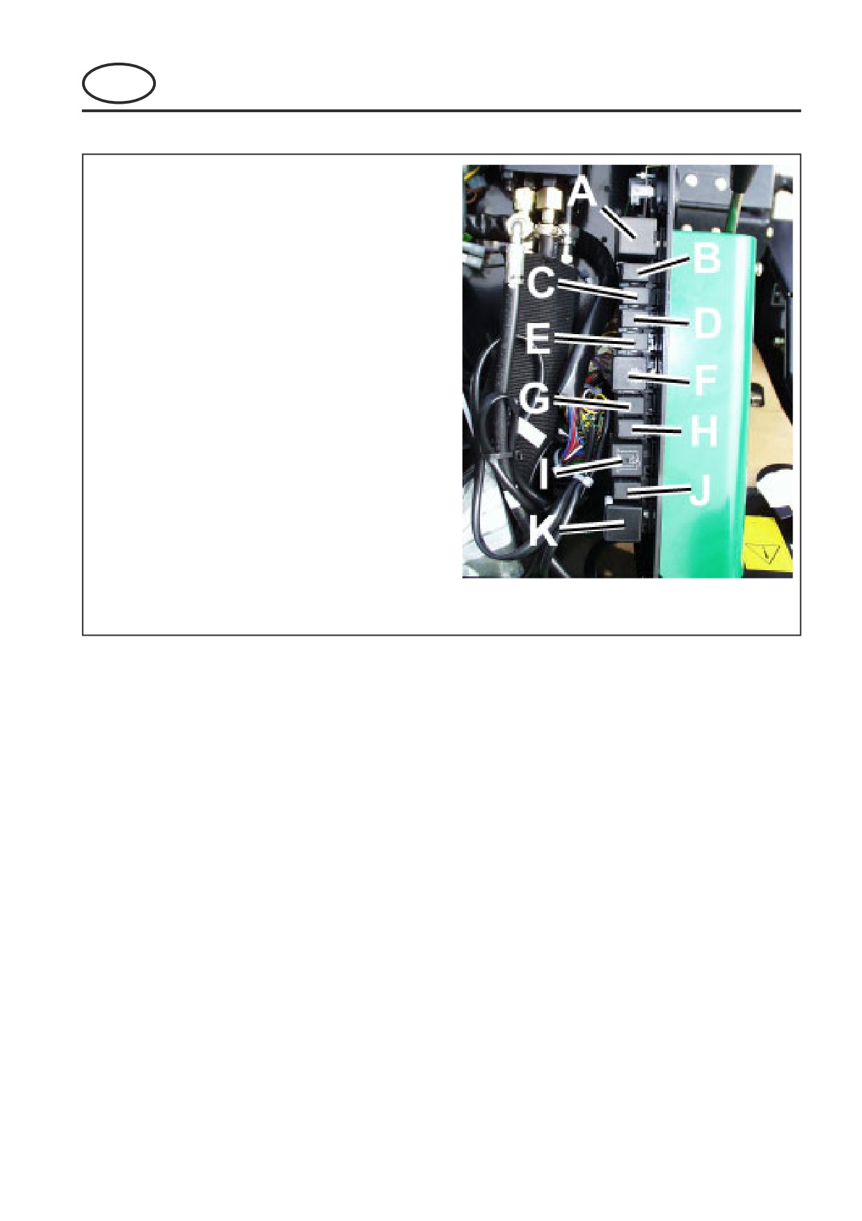
RELAY POSITIONS
RELAY POSITIONS
Relays are situated under the front tower cover
Relay A - Flasher Relay
Relay B - RH Deck Relay
Relay C - Centre Deck Relay
Relay D - LH Deck Relay
Relay E - 4 Wheel Drive Relay
Relay F - Start Relay
Relay G - Horn Relay
Relay H - Alarm Relay
Relay I - Accessory Relay
Relay J - Accessory Control Relay
Relay K - Seat Delay Relay
GB-25
1
TABLE DES MATIERES
FRONTLINE 960 Série : LQ
MANUEL DE MAINTENANCE
F
ET NOMENCLATURE DES PIECES DE RECHANGE
1
TABLE DES MATIERES
2
INTRODUCTION
2.1
IDENTIFICATION DU PRODUIT
2
2.2
STOCKAGE DES PIECES DE RECHANGE
2
2.3
UTILISATION DE LA NOMENCLATURE
3
3
CONSIGNES DE SECURITE
3.1
NOTICE DE FONCTIONNEMENT
4
3.2
VIGNETTES DE SECURITE
4
3.3
DEMARRAGE DU MOTEUR
4
3.4
CONDUITE DE LA MACHINE
4
3.5
TRANSPORT
4
3.6
AVANT DE QUITTER LE POSTE DE CONDUITE
5
3.7
PENTES
5
3.8
BLOCAGE DES PLATEAUX DE COUPE
5
3.9
REGLAGES, GRAISSAGE ET MAINTENANCE
5/6
4
SPECIFICATIONS
4.1
SPECIFICATIONS DU MOTEUR
7
4.2
SPECIFICATIONS DE LA MACHINE
7
4.3
DIMENSIONS
7
4.4
NIVEAU DES VIBRATIONS
7
4.5
PENTES
7
4.6
LUBRIFIANTS RECOMMANDES
8
4.7
RENDEMENT DE COUPE (SURFACE)
8
4.8
COUPLES DE SERRAGE
8
5
GRAISSAGE ET MAINTENANCE
TABLEAU DE MAINTENANCE ET DE GRAISSAGE
9/10
5.1
MOTEUR : 50 PREMIERES HEURES D’HORAMETRE PUIS TOUTES LES 250 HEURES
D’HORAMETRE
11
5.2
MACHINE : GRAISSAGE DES COMPOSANTS SUIVANTS. HEBDOMADAIREMENT OU
TOUTES LES 40 HEURES D’HORAMETRE
11
5.3
MACHINE : TOUTES LES 400 HEURES D’HORAMETRE
12
5.4
ORIFICES D’ESSAIS HYDRAULIQUES
13
5.5
MAINTENANCE DU MOTEUR : TOUTES LES 400 HEURES D’HORAMETRE
14
5.6
MAINTENANCE DU MOTEUR : TOUTES LES 400 HEURES D’HORAMETRE
15
5.7
MAINTENANCE DE LA MACHINE
15
5.8
FIN DE SAISON (OU SELON LA DEMANDE)
16
6
REGLAGES
6.1
LIMITEUR DE VITESSE
17
6.2
PINCEMENT DES ROUES ARRIERE
17
6.3
ALTERNATEUR
17
7
REGLAGE DES PLATEAUX DE COUPE
7.1
TENSION DE LA COURROIE DES PLATEAUX DE COUPE
18
7.2
AFFUTAGE ET DEPOSE DES LAMES
19
8
DEPISTAGE DES DEFAUTS
8.1
GENERALITES
19
9
SCHEMATIQUE
9.1
CIRCUIT HYDRAULIQUE
20
9.2
COMPOSANTS DU CIRCUIT ELECTRIQUE
21
9.3
CIRCUIT ELECTRIQUE PRINCIPAL
22
F-1

2
INTRODUCTION
FRONTLINE 960 Série : LQ
MANUEL DE MAINTENANCE
F
ET NOMENCLATURE DES PIECES DE RECHANGE
2.1
IDENTIFICATION DU PRODUIT
A Nom de la machine
A
B
B Numéro de série
C
C Date de fabrication
D Poids de la machine
D
E
E Puissance moteur
2.2
STOCKAGE DES PIECES DE RECHANGE
Afin d’assurer le fonctionnement et la rentabilité maximum de la machine, Ransomes recommande de
conserver les pièces de rechange les plus courantes. Les numéros de certaines pièces sont également inclus
pour les manuels et aides à la formation.
Pièces de rechange
No. Pièce
Description
No. Pièce
Description
Filtre à huile moteur
178025
Filtre hydra
l
26560017
Filtre à carburant moteur
4126806
Pompe électrique à carburant
4123044
Elément d'épurateur d'air
5001182
Filtre à carburant en
l
008089620
Filtre hydra
l
(Charge)
Documents d'appui
No. Pièce
Description
No. Pièce
Description
Manuel de
Nomenclature de s
maintenance et
pièces de rechange
24598 G
nomenclature de s
de moteur
pièces de rechange
Manuel de l'utilisateur
Manuel de sécurité et
24597 G
de moteur
de l'opérateur
Manuel de service de
Manuel de service de
-
moteur
la machin e
F-2
2
INTRODUCTION
FRONTLINE 960 Série : LQ
MANUEL DE MAINTENANCE
F
ET NOMENCLATURE DES PIECES DE RECHANGE
2.3
UTILISATION DE LA NOMENCLATURE
NUMERO D'ARTICLE
Chaque pièce, identifiée sur les illustrations, est accompagnée d'un numéro. Il peut s'avérer difficile d'identifier
les pièces ne possédant pas de numéro, mais celles-ci sont généralement étroitement associées à la pièce
immédiatement adjacente.
ENSEMBLES/BLOCS
Un bloc complet, par exemple : un bloc moteur de roue, de moteur hydraulique ou de rouleau, est représenté
par le bloc entier et ses composant s sont représentés séparément. Le bloc parait sous son numéro de pièce et
les composants sont décalés vers la droite sur la liste, par exemple :
ARTICLE NO. PIECE
DESCRIPTION
QTE
REMARQUES
RANSOMES
4295
MBG2504
BRIDE
1
4296
MBG3848
VERROU
2
4298
450865
VIS A TETE FRAISEE M8 x 20
2
4300
450378
ECROU M8, NYLOC
2
4301
Wl001
Jeu de roues
1
4301.1
008162130
• Roue & moyeu
1
(Arrière)
4301.2
008170390
• • Pneu
1
4301.3
008161830
• • Jante
1
4301.4
008169140
• • Moyeu
1
4301.5
008169150
• • Chapeau
1
4301.6
002993010
• • Graisseur
1
4301.7
008161990
• Roue & moyeu
2
(Avant)
4301.8
008170780
• • Pneu
2
Il se peut que l'illustration de tous les articles ne soit pas possible. Pour certains articles achetés à des
fournisseurs externes, il se peut que des composants ne soient pas disponibles chez Ransomes et que ceux-ci
doivent être commandés spécialement auprès du fournisseur.
QUANTITES
Les quantités indiquées s'appliquent à un ensemble ou sous-ensemble.
UTILISATION DE LA LISTE DE PIECES
Déterminez la fonction et l'application de la pièce requise. Repérez l'index principal et sélectionnez la section
appropriée. Identifiez la pièce sur l'illustration et la nomenclature, puis notez la quantité dans la colonne
adjacente intitulée MODELE.
INDEX NUMERIQUE
Il s'agit d'un récapitulatif de tous les numéros de pièces utilisés dans le manuel, classés numériquement, et
indiquant la page et le numéro d'article sous lesquels les pièces paraissent.
COMMANDE DES PIECES DE RECHANGE
Lors de la commande des pièces de rechange, stipulez le NUMERO DE SERIE de la machine, le NUMERO DE
LA PIECE, la DESCRIPTION et la QUANTITE requise.
00Le fabriquant n'est pas responsable des accidents ou endommagements pouvant résulter de modifications
apportées à la machine sans son accord préalable.
ABBREVIATIONS
N/D Non Disponible
SC Selon la Commande
F-3
//////////////////////