Takeuchi Hydraulic excavator TB1160W (Serial No. 514500002~). Operator's Manual (2016) - page 7
MAINTENANCE
WHEN REQUIRED
INSPECTING AND REPLENISHING THE
Inspection
WINDSHIELD WASHER FLUID
1. Open the left side cover.
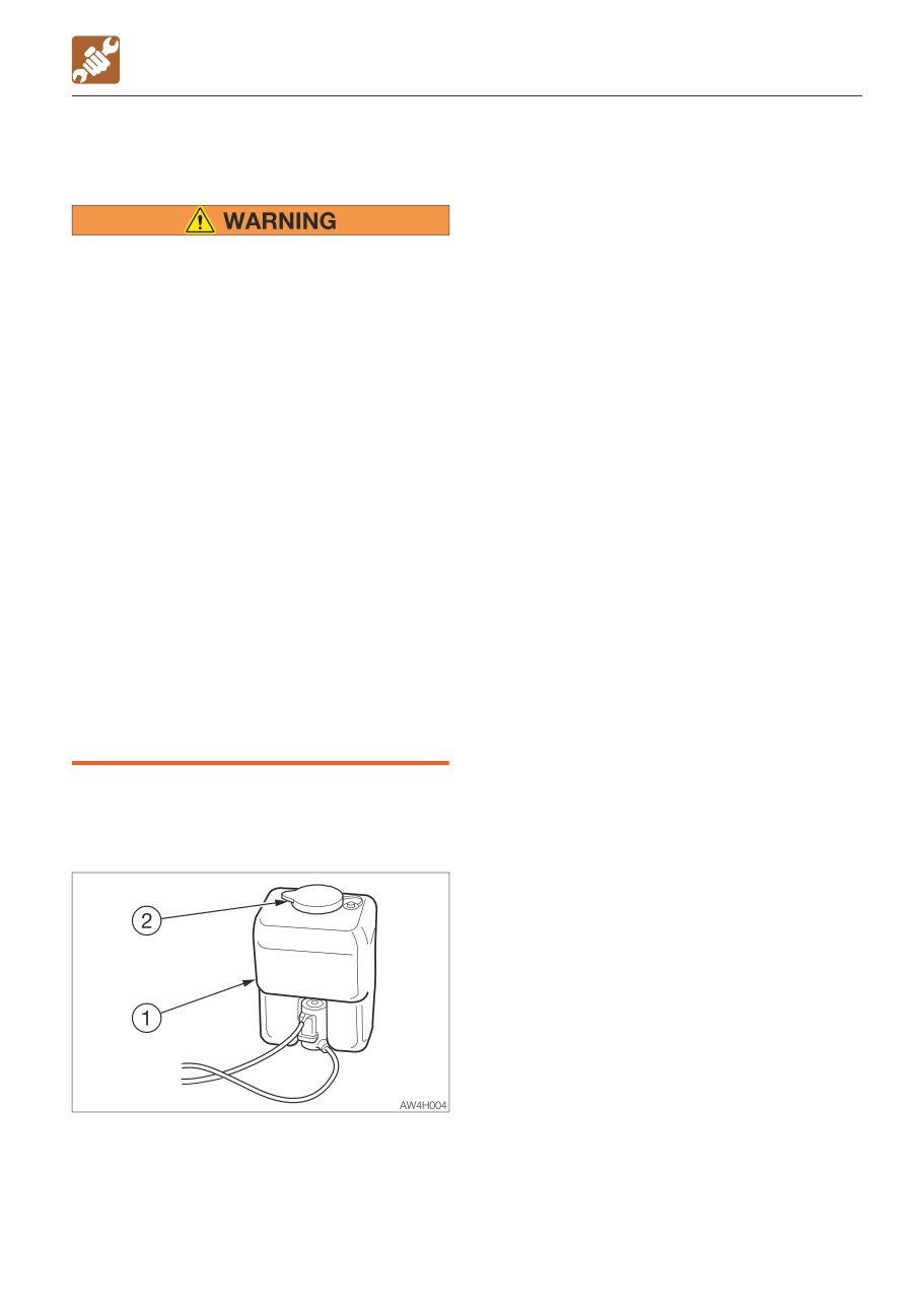
2. Inspect the washer tank (1) and add
washer fluid if the level is low.
• Choose ethyl alcohol as washer
Replenishing
solution.
1. Mix the washer fluid to the prescribed
Do not use methyl alcohol as washer
concentration.
solution. It could damage the eyes.
2. Remove the cap (2) and add washer fluid.
• Before performing maintenance on top
Keep the dust away while replenishing the
of the work bench, clean the footing and
washer fluid.
observe the following precautions to
3. Install the cap (2).
prevent falling.
· Do not spill oil or grease.
· Do not leave tools scattered around.
· Watch your step when walking.
• Never jump down from the machine or
the work bench. When getting on or off
the machine or work bench, use the
steps, handrails or work bench to
support your body. Your weight should
be evenly distributed among the three
contact points (one hand and two feet
or two hands and one foot).
• Do not stand on the dozer blade and
perform maintenance work. Doing so is
dangerous because of the unsteady
foothold. Use the work bench.
Use a windshield washer fluid designed
specifically for motor vehicles. Follow the
instructions included with the washer fluid.
5-75
MAINTENANCE
WHEN REQUIRED
DRAINING THE WATER FROM THE
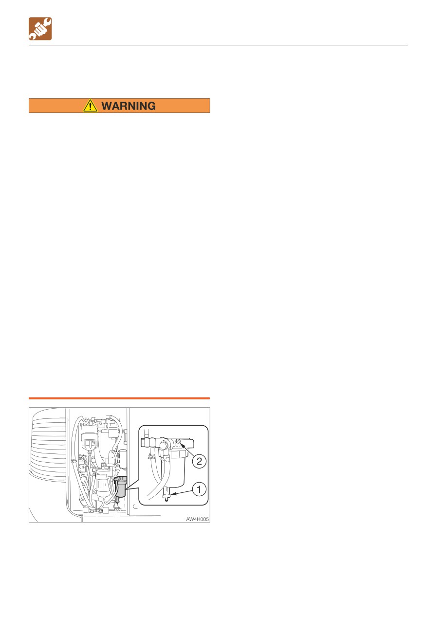
If the water does not drain easily, loosen
WATER SEPARATOR
the plug (2).
4. Close the drain valve (1) and tighten the
plug (2).
Refer to “Bleeding air from the fuel
• Do not smoke or permit open flames
system” on page 6-10.
while handling fuel or working on the
fuel system.
• Stop the engine in a well-ventilated
place and allow it to cool down before
performing maintenance.
• Clean up spilled fuel immediately.
• Before performing maintenance on top
of the work bench, clean the footing and
observe the following precautions to
prevent falling.
· Do not spill oil or grease.
· Do not leave tools scattered around.
· Watch your step when walking.
• Never jump down from the machine or
the work bench. When getting on or off
the machine or work bench, use the
steps, handrails or work bench to
support your body. Your weight should
be evenly distributed among the three
contact points (one hand and two feet
or two hands and one foot).
• Do not stand on the dozer blade and
perform maintenance work. Doing so is
dangerous because of the unsteady
foothold. Use the work bench.
1. Open the right side cover.
2. Place a pan under the drain valve (1) to
catch fuel.
3. Open the drain valve (1) and drain the
water.
5-76
MAINTENANCE
WHEN REQUIRED
LUBRICATING THE LEVERS AND PEDAL
Dozer blade lever
Set the machine to the parking posture,
stop the engine, remove the starter key
and store it. Failure to do so may result in
the machine moving abruptly, leading to
serious injury or death.
If the levers or pedals no longer move
smoothly, grease them.
Operating levers
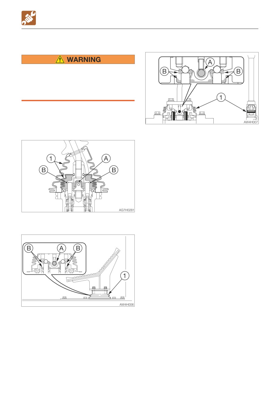
1. Remove the lower mount section of the
boot (1) and turn it upward.
2. Wipe off the old grease.
3. Apply grease to points (A) and (B).
4. Set the boot (1) back as it was.
Second boom pedal
5-77
MAINTENANCE
EVERY 2 YEARS
EVERY 2 YEARS
REPLACING THE RECEIVER DRYER
This operation requires experience. Ask your
sales or service dealer for it.
5-78
MAINTENANCE
MAINTENANCE DURING EXTENDED STORAGE PERIOD
Starting the machine after storage
MAINTENANCE DURING
IMPORTANT: If the above “Storage
EXTENDED STORAGE PERIOD
procedures” have not been followed
Storage procedures
during the extended storage periods,
If the machine is to be stored for 30 days or
consult your sales or service dealer
more, store it indoors. If it must be stored
before starting the machine again.
outdoors, park the machine on a surface laid
with lumber on a flat ground, and place a
1. Wipe off the rust-inhibiting oil that was
waterproof cover over it so that it stays dry.
applied on the piston rods of the hydraulic
1. Clean the machine.
oil cylinders.
2. Inspect for oil leakage, water leakage,
2. Add oil or grease as necessary.
cracks and loose nuts and bolts.
3. Add fuel and replace the hydraulic oil and
Returning the engine to service
oil.
1. Perform the daily checks.
4. To prevent rusting and freezing, replace
2. The engine should be pre-oiled before
the engine coolant with long-life coolant
startup.
(LLC).
a. Crank the engine, leaving the fuel
Refer to “Cleaning the engine cooling
system shut off so the engine will not
system” on page 5-57.
start, for 15 seconds.
5. Use the grease gun to lubricate the grease
b. Then pause for 30 seconds.
fittings.
c. Repeat the procedure until you have
6. Fully retract the bucket and arm cylinders
cranked the engine for a total of one
and lower the bucket and dozer blade to
minute. This will circulate the oil in the
the ground.
engine’s lubrication system.
7. Apply rust-inhibiting oil to the hydraulic
3. Prime the fuel system.
cylinder rods.
4. Start the engine. Allow the engine to idle
8. Disconnect the negative cable from the
for approximately 15 minutes while you
battery and cover the battery to prevent
check for:
freezing.
· Proper oil pressure
· Fuel, engine oil or coolant leaks
During storage
· Proper operation of the indicators and/or
gauges
5. Avoid prolonged operation at minimum or
• Do not operate the machine in an
maximum engine speeds and loads for the
enclosed area without adequate
remainder of the first hour of operation.
ventilation.
• If natural ventilation is not possible,
install ventilators, fans, exhaust
extension pipes or other venting
devices.
1. To prevent rusting, operate the machine
once a month so that the oil can be
circulated throughout the system.
2. Inspect the battery and recharge it as
necessary.
Ask your sales or service dealer for
recharging.
5-79
5-80
TROUBLESHOOTING
6-1
TROUBLESHOOTING
SYMPTOMS THAT ARE NOT MALFUNCTIONS
• It becomes less easy to operate the
SYMPTOMS THAT ARE NOT
machine when an attachment weighing
more than a standard arm or bucket is
MALFUNCTIONS
installed.
The symptoms listed below are not
• In some cases smoke may be emitted from
malfunctions.
the tail pipe while the DPD regeneration is
being performed. This is not a failure; it is
due to burning of the particulate matter
(PM).
• In some cases the noise associated with
the DPD regeneration operation or cancel
operation may change; this is not a failure.
AG7J002
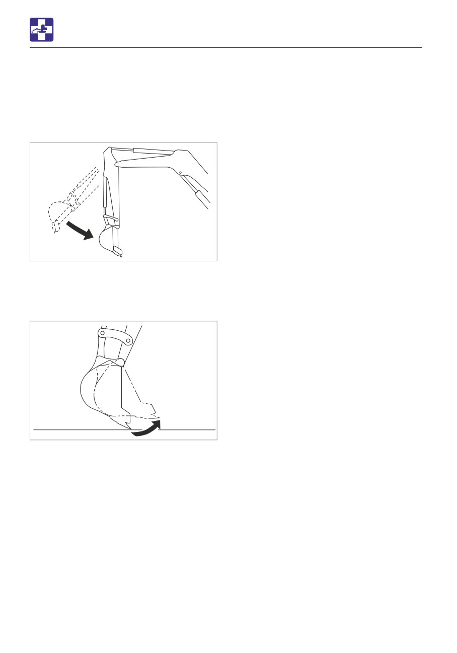
• The arm retracting speed momentarily
slows down when it reaches an almost
vertical position while the engine is running
at low speed.
AG7J003
• The bucket teeth moving speed
momentarily slows down when it reaches
an almost horizontal position while the
engine is running at low speed.
• The slew motor produces noise at the
beginning and end of the slewing.
• The travel motor produces noise when
stopped suddenly from its high speed
traveling.
• The control valve produces noise if
excessive force is applied to the working
equipment or when it moved to the stroke
end.
6-2
MEMO
6-3
TROUBLESHOOTING
IF THE ENGINE OVERHEATS
The symptoms listed below indicate
IF THE ENGINE OVERHEATS
overheating.
• Do not open the engine hood when
steam is coming from it. The steam or
hot water may spurt out and cause
burns.
• Do not remove the radiator cap or the
drain plug when the coolant is hot. Stop
the engine and wait until the engine and
the radiator cool. Then, slowly loosen
the radiator cap to release the internal
pressure.
• Before performing maintenance, stop
the engine and allow the machine to
cool down.
• Before performing maintenance on top
of the work bench, clean the footing and
observe the following precautions to
prevent falling.
· Do not spill oil or grease.
· Do not leave tools scattered around.
· Watch your step when walking.
• Never jump down from the machine or
the work bench. When getting on or off
the machine or work bench, use the
steps, handrails or work bench to
support your body. Your weight should
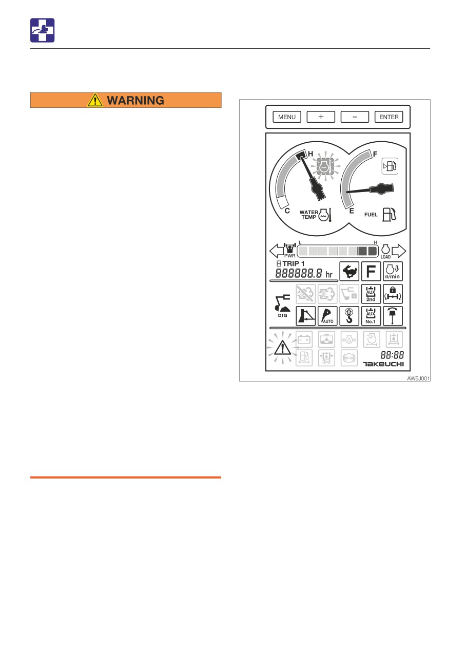
• An alarm is sounded and the vehicle/
be evenly distributed among the three
engine emergency lamp and the coolant
contact points (one hand and two feet
temperature warning lamp start flashing.
or two hands and one foot).
• The water temperature gauge needle is in
• Do not stand on the dozer blade and
the red zone.
perform maintenance work. Doing so is
• Steam comes from the engine room.
dangerous because of the unsteady
foothold. Use the work bench.
6-4
TROUBLESHOOTING
IF THE ENGINE OVERHEATS
Remedy procedure
1. Park the machine in a safe place.
2. Check if steam is coming out of the closed
engine hood.
3. If there is steam, stop the engine
immediately and contact your sales or
service dealer for repair. If steam, is not
coming out run the engine at low idle and
let the water temperature cool down.
4. When the water temperature gauge
needle drops in the green zone, stop the
engine.
5. Perform the inspections and the remedies
listed below once the engine cools down.
· V belt slack
Adjust
Refer to page 5-30.
· Coolant level
Add
Refer to page 5-20.
· Water leakage
Repair
· Radiator fins
Clean
Refer to page 5-42.
· Sediment in cooling system
............................... Clean
Refer to page 5-57.
If the problem persists after the above
remedies, contact your sales or service
dealer for repair.
6-5
TROUBLESHOOTING
IF THE BATTERY GOES DEAD
Connecting the jumper cables
IF THE BATTERY GOES DEAD
The symptoms below indicate that the
IMPORTANT: Set the starter keys of the
battery is dead.
booster vehicle and the dead machine to
• The starter motor does not turn or fails to
the OFF position.
start the engine.
• The horn is too weak.
Remedy procedure
Start the engine using the booster battery on
the other vehicle (booster vehicle) and the
jumper cables.
• When starting the engine using the
jumper cables, be sure to connect the
cables by following the proper steps.
Improper use of jumper cables can
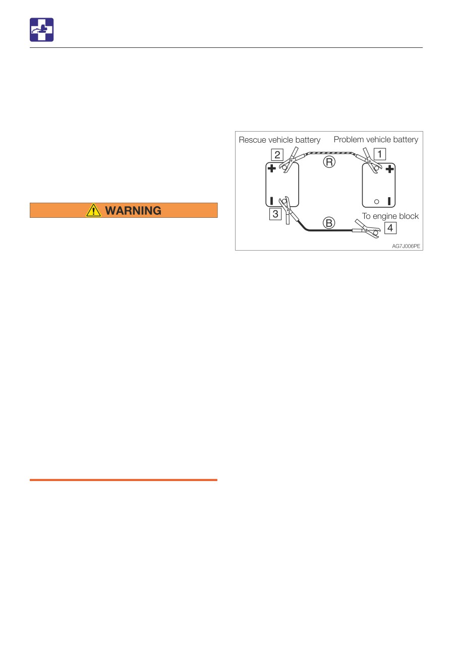
1. Connect the clip of jumper cable (R) to the
result in battery explosion or
positive (+) battery terminal of the dead
unexpected machine motion.
machine.
· Do not allow the booster vehicle and
2. Connect the other clip of jumper cable (R)
the machine with a dead battery (dead
to the positive (+) battery terminal of the
machine) to touch each other.
booster vehicle.
· Do not allow the positive (+) and the
3. Connect the clip of jumper cable (B) to the
negative (-) clips of the jumper cables
negative (-) battery terminal of the booster
to touch each other.
vehicle.
· When connecting, attach the jumper
4. Connect the other clip of jumper cable (B)
cable to the positive (+) terminals first.
to the engine block of the dead machine.
When disconnecting, remove the
Connect the clip to a place as far from the
cable from the negative (-) terminal
battery as possible.
(ground) first.
· Connect the last clip of the jumper
Starting the engine
cable to a point as far away from the
1. Check that the clips are securely
battery as possible.
connected to the terminals.
• Always wear the protective goggle when
2. Start the engine of the booster vehicle and
jump starting the engine by using the
run it at high speed.
jumper cables.
3. Start the engine of the dead machine.
IMPORTANT: Use the jumper cables and
clips of a size suited to the capacity of
battery. Do not use damaged or corroded
jumper cables and clips.
IMPORTANT: Be sure that the battery of
the booster vehicle has the same
capacity as the battery of the dead
machine.
IMPORTANT: Be sure to connect the clips
securely.
6-6
TROUBLESHOOTING
IF THE BATTERY GOES DEAD
Disconnecting the jumper cables
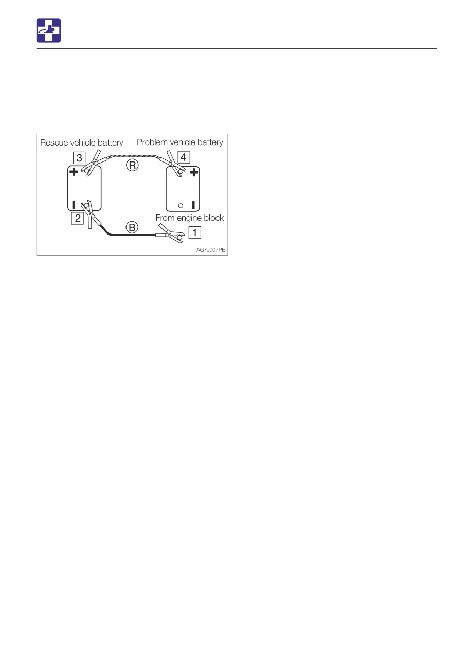
Once the dead machine is successfully
running, remove the jumper cables by
following the same steps as for connection in
the reverse order.
1. Disconnect the clip of jumper cable (B)
from the engine block of the dead
machine.
2. Disconnect the other clip of jumper cable
(B) from the negative (-) battery terminal of
the booster vehicle.
3. Disconnect the clip of jumper cable (R)
from the positive (+) battery terminal of the
booster vehicle.
4. Disconnect the clip of jumper cable (R)
from the positive (+) battery terminal of the
dead machine.
Recharging
Ask your sales or service dealer for
recharging the dead battery.
6-7
TROUBLESHOOTING
IF A FUSE BLOWS
Fuse layout and circuits protected
IF A FUSE BLOWS
If a light does not come on or the electrical
Capacity
Symbol
Protected circuit
system does not work, a fuse may be blown.
Inspect the fuses.
10A
Head light low Beam (2)
INSPECTING AND REPLACING THE FUSE
10A
Head light low Beam (1)
3A
Position lamps (3)
If the fuse blows again soon after
10A
Turn Signal (3)
replacement, then the electric system is
likely faulty. It may pose a fire hazard if
10A
Turn Signal (2)
not properly repaired. Contact your sales
or service dealer for advice.
10A
Starter switch
Brake lamp
1. Turn the starter key to the OFF position to
10A
/Reverse light
stop the engine.
20A
Head light high Beam (2)
10A
Turn Signal (1)
5A
Head light high Beam (1)
Air conditioner
20A
compressor
25A
AC motor
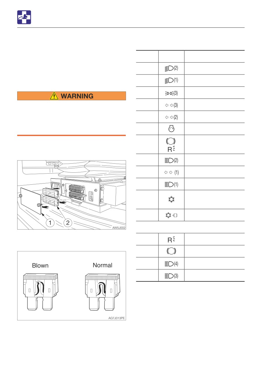
2. Open the fuse box covers (1) and (2).
3. Inspect for blown fuses.
10A
Reverse light
10A
Brake lamp
10A
Head light high Beam (4)
10A
Head light high Beam (3)
4. If a fuse is blown, replace it with a spare
fuse of the same capacity.
6-8
TROUBLESHOOTING
IF A FUSE BLOWS
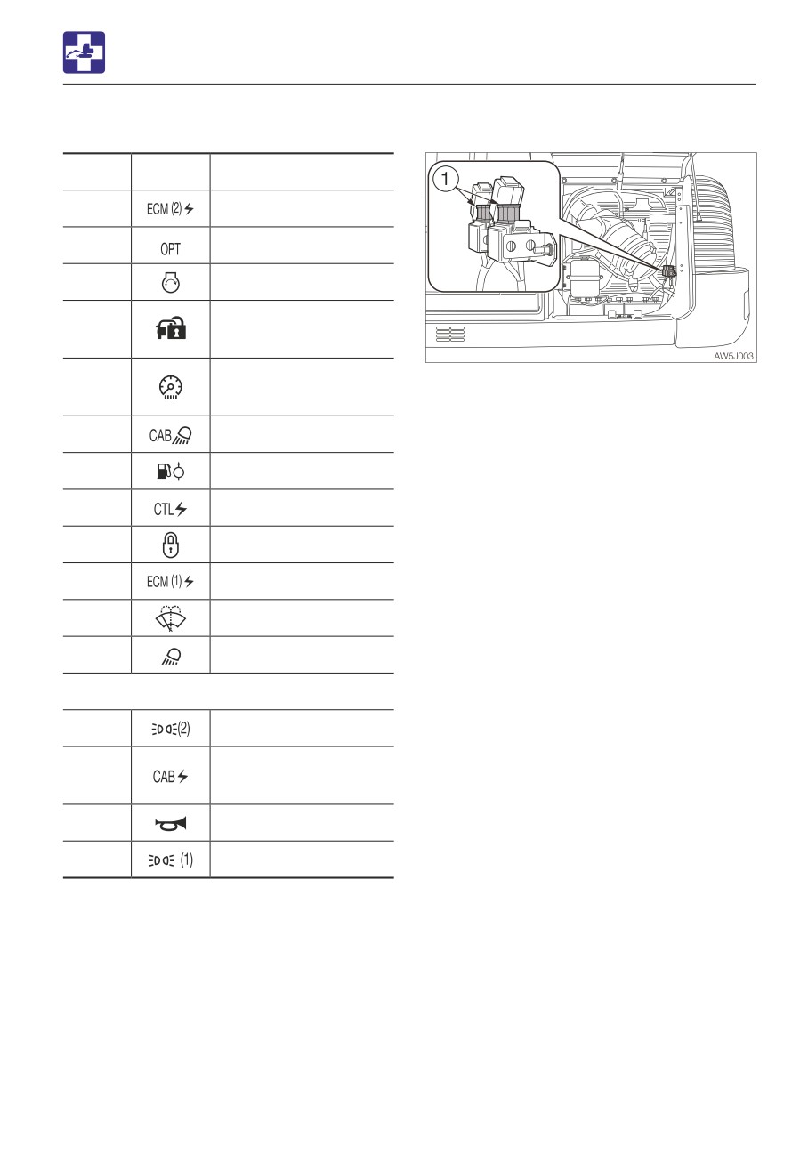
INSPECTING THE FUSIBLE LINK
Capacity
Symbol
Protected circuit
10A
ECM (2) power source
25A
Option
10A
Starter switch
Immobilizer power
5A
source
Multi-information
If the machine is not turned on after turning
20A
display
the starter switch to the ON position, the
cartridge type fusible links (1) is likely blown.
30A
Cab power supply
Open the left side cover for inspection. If the
fusible link is blown, contact your sales or
5A
Feed pump
service dealer.
10A
Controller power supply
Note: Fusible links are large type fuses used
in high current applications. Like a regular
15A
Lever lock
fuse, they act as fuses by protecting the
electric components and wirings from
10A
ECM (1) power source
damage caused by excessive current draw.
10A
Wiper
20A
Light
3A
Position lamps (2)
Cab interior power
5A
supply
10A
Horn
3A
Position lamps (1)
6-9
TROUBLESHOOTING
RESTARTING AFTER ADDING FUEL
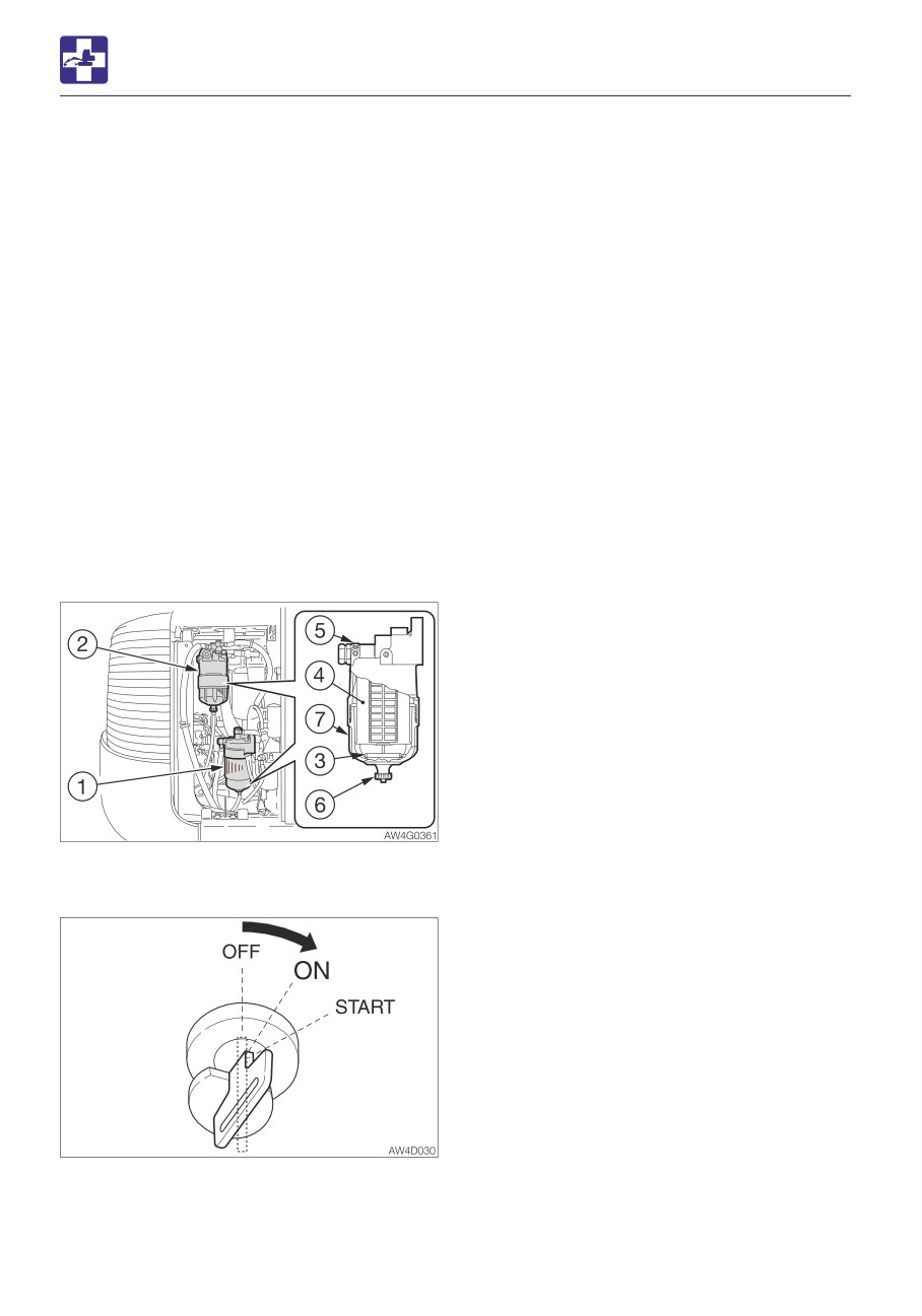
4. Retighten the vent plug (5) when air
RESTARTING AFTER ADDING
bleeding is finished and fuel starts leaking
out from around the vent plug (5).
FUEL
· Tightening torque: 8 to 12 N·m (6 to 9
BLEEDING AIR FROM THE FUEL SYSTEM
ft-lb)
5. Turn and hold the starter key to the ON
IMPORTANT: NEVER use the starter
position for three minutes before turning it
motor to crank the engine in order to
back to the OFF position.
prime the fuel system. This may cause the
starter motor to overheat and damage the
Note: Air in the fuel system causes the
coils, pinion gear and/or ring gear.
engine to fail to start or to have other
IMPORTANT: If the engine stalls due to
problems. Always bleed air when the fuel
fuel shortage, add fuel, turn the key to the
tank is emptied or when there is air in the
ON position for 60 seconds, and then turn
fuel system.
it to the START position. Running the
starter for a long time before there is
enough fuel is going through can cause
the starter to fail.
1. Add fuel.
2. Loosen the vent plug (5) of the main fuel
filter (2).
3. Turn the starter key to the ON position and
wait for the air to be bled from the vent
plug (5).
6-10
MEMO
6-11
TROUBLESHOOTING
IF A WARNING LAMP FLASHES
IF A WARNING LAMP FLASHES
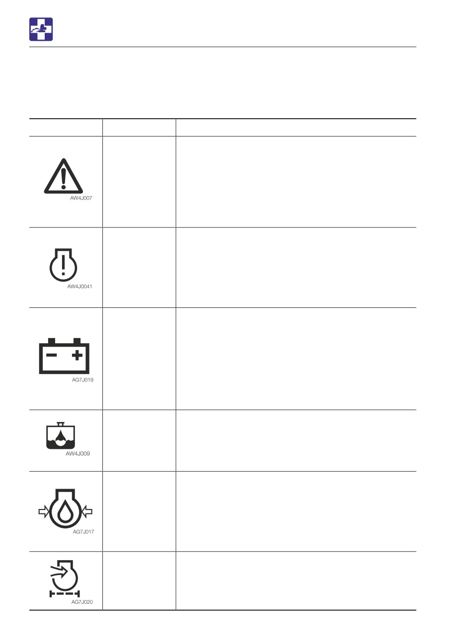
If an alarm is sounded or a warning lamp starts flashing during operation, park the machine in
a safe place and perform the remedy procedures described below.
Warning lamp
Lamp name
Causes and remedies
Vehicle and
There is a problem in the machine.
engine
Refer to the respective warning lamp below.
emergency
Get the vehicle or engine error code number from the
lamp
multi-information display and consult your sales or
service dealer referring to the “Vehicle error code list” or
“Engine error code list”.
Refer to “Vehicle error code list” on page 6-14.
Refer to “Engine error code list” on page 6-16.
ECM error
There is a problem in the engine.
warning lamp
If an error code is displayed on the multi-information
display, inform your sales or service dealer of the code
and ask for help.
Refer to “Multi-information display” on 2-16.
Refer to “Engine error code list” on page 6-16.
Battery charge
There is a problem with the V-belt or charger.
warning lamp
Check the fan belt for slack or breakage and adjust as
necessary.
If the lamp continues flashing after maintenance, there is
likely a problem with the charger. Consult your sales or
service dealer for help.
Refer to “Inspecting and adjusting the V-belt” on page
5-30.
Water
Water is in the water separator. Drain water.
separator
Refer to “Draining the water from the water separator” on
warning lamp
page 5-76.
Engine oil
There is a problem in the engine lubrication system.
pressure
warning lamp
Check the engine oil level. If the lamp is flashing when
the level is normal or even after replenishment of oil or
coolant, consult your sales or service dealer.
Refer to “Inspecting and replenishing the engine oil” on
page 5-21.
Air cleaner
The air cleaner is clogged. Clean it.
warning lamp
Refer to “Cleaning the air cleaner” on page 5-43.
6-12
TROUBLESHOOTING
IF A WARNING LAMP FLASHES
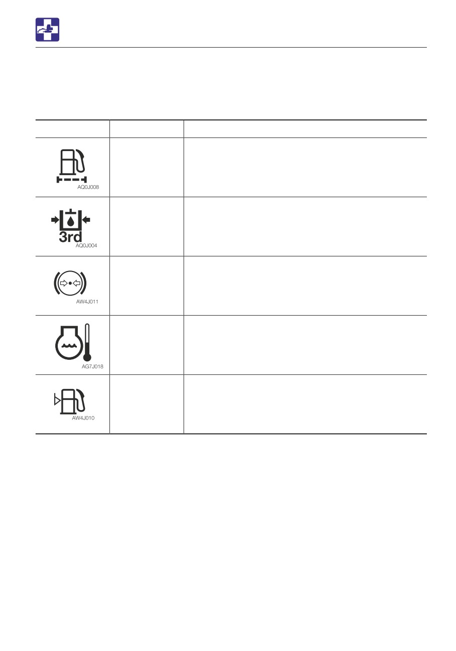
Warning lamp
Lamp name
Causes and remedies
Fuel filter
The fuel filter is clogged. Replace the fuel filter.
warning lamp
Refer to “Replacing the fuel filter” on page 5-53.
Third auxiliary
Pressure in the third auxiliary hydraulic line is too low
hydraulic
warning lamp
Consult your sales or service dealer for help.
Brake oil
The brake oil pressure is too low.
pressure
warning lamp
Consult your sales or service dealer for help.
Coolant
The coolant temperature is too high and the engine is
temperature
overheating.
warning lamp
Refer to “If the engine overheats” on page 6-4.
Fuel level
The fuel level is too low. Add fuel.
warning lamp
Refer to “Inspecting the fuel level” on page 5-23.
6-13
TROUBLESHOOTING
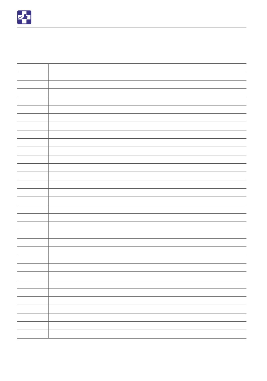
ERROR CODE LIST
VEHICLE ERROR CODE LIST
If an error code appears on the display, consult your sales or service dealer.
Error code
Error details
9
Impossible to sense ACC key
19
Parameter version mismatching
402
CAN 0 communication error
502
CAN communication error (ECM)
602
CAN communication error (cluster gauge)
612
CAN communication error (MOX024)
622
CAN communication error (MIX024)
632
CAN communication error (SOX024)
642
CAN communication error (SIX024)
702
CAN communication error (HVAC)
1703
Main power supply voltage error (too high)
1704
Main power supply voltage error (too low)
1713
MOX024 power supply voltage error (too high)
1714
MOX024 power supply voltage error (too low)
1723
MIX024 power supply voltage error (too high)
1724
MIX024 power supply voltage error (too low)
1733
SOX024 power supply voltage error (too high)
1734
SOX024 power supply voltage error (too low)
1743
SIX024 power supply voltage error (too high)
1744
SIX024 power supply voltage error (too low)
2503
Sensor voltage error (too high) MMC
2504
Sensor voltage error (too low) MMC
2513
Sensor voltage error (too high) MIX
2514
Sensor voltage error (too low) MIX
2523
Sensor voltage error (too high) SIX
2524
Sensor voltage error (too low) SIX
3300
Alternator charge faulty
3401
Engine oil pressure error
3500
Overheat
3600
Air cleaner clogged
3700
Water separator alarm
3820
Hydraulic oil temp. overheat
6-14
TROUBLESHOOTING
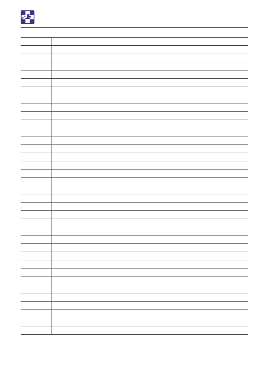
ERROR CODE LIST
Error code
Error details
3825
Wire break in hydraulic oil temp. sensor
3350
Fuel filter clogged (phase 1)
3359
Fuel filter clogged (phase 2)
3360
DPD over trapping
5303
Accelerator sensor error (too high)
5304
Accelerator sensor error (too low)
5313
Foot accelerator sensor error (high pressure)
5314
Foot accelerator sensor error (low pressure)
5505
Fuel gauge resistance value error(too low)
5603
Lift alarm sensor error (too high)
5604
Lift alarm sensor error (too low)
6503
AUX1 slide switch voltage value error (too high)
6504
AUX1 slide switch voltage value error (too low)
6509
AUX1 slide switch neutral error
6519
AUX1 (L) switch error
6529
AUX1 (R) switch error
6603
AUX2 slide switch voltage value error (too high)
6604
AUX2 slide switch voltage value error (too low)
6609
AUX2 slide switch neutral error
6709
AUX3 button error (Grip)
6719
AUX3 switch error (Foot)
6809
Ram lock switch error
6819
Blade/outrigger switch error
8005
Pump PWM output voltage error (too low)
8006
Pump PWM output voltage error (too high)
8015
AUX1 (L) PWM output voltage error (too low)
8016
AUX1 (L) PWM output voltage error (too high)
8025
AUX1 (R) PWM output voltage error (too low)
8026
AUX1 (R) PWM output voltage error (too high)
8035
AUX2 (L) PWM output voltage error (too low)
8036
AUX2 (L) PWM output voltage error (too high)
8045
AUX2 (R) PWM output voltage error (too low)
8046
AUX2 (R) PWM output voltage error (too high)
8055
Fan drive PWM output voltage error (low pressure)
8056
Fan drive PWM output voltage error (high pressure)
PWM = Pulse width modulation
6-15
TROUBLESHOOTING
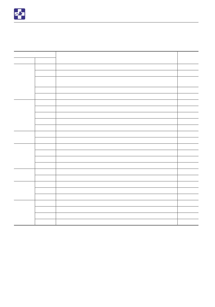
ENGINE ERROR CODE LIST
ENGINE ERROR CODE LIST
If an error code appears on the display, consult your sales or service dealer.
Error code
Error details
DTC
SPN
FMI
0
DPD differential pressure high
P2453
1
DPD differential pressure low
P2452
Zero-point learning error in the DPD differential pressure
81
2
P2456
sensor
3
DPD differential pressure sensor error (high-voltage error)
P2455
4
DPD differential pressure sensor error (low-voltage error)
P2454
3
Accelerator sensor 1 error (high-voltage error)
P2123
4
Accelerator sensor 1 error (low-voltage error)
P2122
91
2
Accelerator sensor 1-2 comparison error
P2138
3
Accelerator sensor 2 error (high-voltage error)
P2128
4
Accelerator sensor 2 error (low-voltage error)
P2127
3
Engine oil pressure sensor error (high-voltage error)
P0523
100
4
Engine oil pressure sensor error (low-voltage error)
P0522
0
Turbo boost pressure, over
P0234
1
Turbo boost pressure, under
P0299
102
3
Boost pressure sensor error (high-voltage error)
P0238
4
Boost pressure sensor error (low-voltage error)
P0237
3
Turbo boost temp. sensor error (high-voltage error)
P1113
105
4
Turbo boost temp. sensor error (low-voltage error)
P1112
2
Barometric sensor error
P2227
108
3
Barometric sensor error (high-voltage error)
P2229
4
Barometric sensor error (low-voltage error)
P2228
0
Engine overheat
P0217
2
Water temp. sensor error
P0116
110
3
Water temp. sensor error (high-voltage error)
P0118
4
Water temp. sensor error (low-voltage error)
P0117
6-16
TROUBLESHOOTING
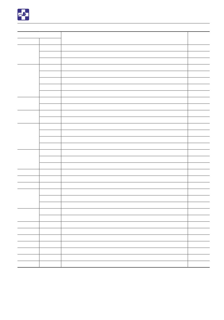
ENGINE ERROR CODE LIST
Error code
Error details
DTC
SPN
FMI
2
Air flow sensor error
P0101
132
3
Air flow sensor error (high-voltage error)
P0103
4
Air flow sensor error (low-voltage error)
P0102
3
Common rail pressure sensor error (high-voltage error)
P0193
4
Common rail pressure sensor error (low-voltage error)
P0192
157
0
Common rail pressure rise (2nd stage)
P0088
15
Common rail pressure error (over pumping)
P0089
16
Common rail pressure rise (1st stage)
P0088
3
Battery line high-voltage error
P0563
158
4
Battery line low-voltage error
P0562
3
Air-intake temp. sensor error (high-voltage error)
P0113
172
4
Air-intake temp. sensor error (low-voltage error)
P0112
0
Exhaust temp. sensor 1 high-temp. error (CSF inlet)
P0426
1
Exhaust temp. sensor 1 low-temp. error (CSF inlet)
P0426
173
3
Exhaust temp. sensor 1 error (CSF inlet) (high-voltage error)
P0428
4
Exhaust temp. sensor 1 error (CSF inlet) (low-voltage error)
P0427
2
Fuel temp. sensor error
P0181
174
3
Fuel temp. sensor error (high-voltage error)
P0183
4
Fuel temp. sensor error (low-voltage error)
P0182
190
0
Engine overspeed
P0219
628
2
ROM error
P0601
633
7
Pressure limitter open
P0087
2
Cam sensor error (no signal)
P0340
636
2
Cam sensor error (abnormal signal)
P0340
7
Cam-Crank phase error
P0016
2
CAN timeout error
U0101
639
19
CAN BusOff error
U0073
651
5
Injector #1 failure
P0201
652
5
Injector #2 failure
P0202
653
5
Injector #3 failure
P0203
654
5
Injector #4 failure
P0204
675
5
Glow lamp failure
P0381
676
5
Glow relay failure
P0380
677
5
Starter cut relay failure
P0615
6-17
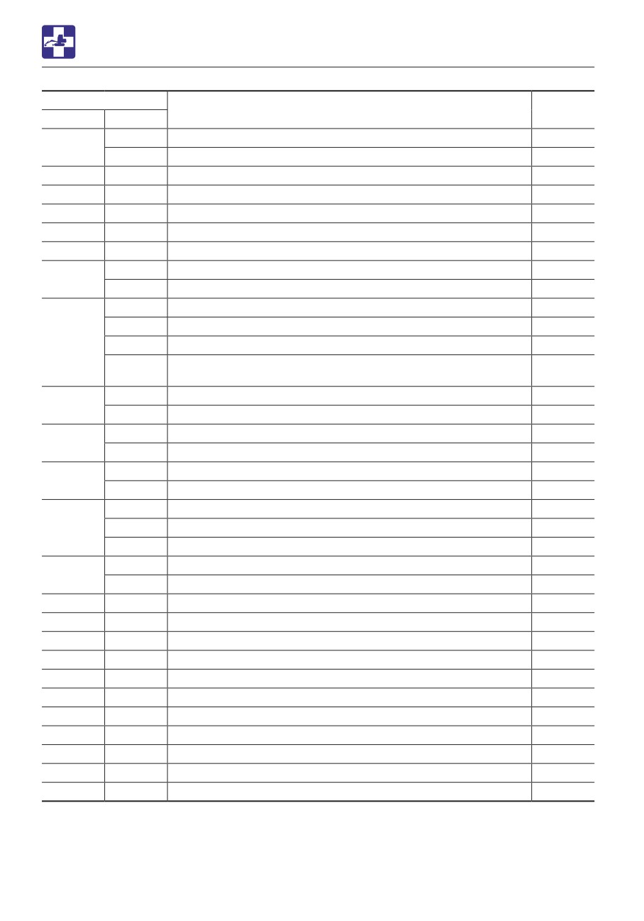
TROUBLESHOOTING
ENGINE ERROR CODE LIST
Error code
Error details
DTC
SPN
FMI
2
Crank sensor error (no signal)
P0335
723
2
Crank sensor error (abnormal signal)
P0336
968
2
Idle up/down switch failure
P256A
987
5
Check engine lamp error
P0650
1077
2
CPU error
P0606
1079
2
5V power system 1 error
P0641
1080
2
5V power system 2 error
P0651
3
Manifold temp. sensor error (high-voltage error)
P041C
1131
4
Manifold temp. sensor error (low-voltage error)
P041D
1
Common rail pressure drop (no pumping)
P0093
17
Common rail pressure drop (insufficient pumping)
P1093
1239
31
Common rail pressure drop (no pumping) <at low fuel temp.>
P0093
Common rail pressure drop (insufficient pumping) <at low fuel
31
P1093
temp.>
3
SCV high-voltage error
P0092
1347
4
SCV low-voltage error
P0091
3
Fuel filter clogging sensor error (high-voltage error)
P1294
1381
4
Fuel filter clogging sensor error (low-voltage error)
P1293
5
Main relay system error (not activated)
P0685
1485
6
Main relay line error (not shut off)
P0687
0
EGR Open faulty
P042F
2791
1
EGR Close faulty
P042E
2
EGR flow rate error
P0401
2
EGR position sensor error (brushless specified)
P0409
10001
13
EGR zero-point learning error
P1404
10002
2
EGR valve control error
P0404
10003
2
Injector com 1 error
P2146
10004
2
Injector com 2 error
P2149
10005
1
Charge circuit error (bank 1)
P1261
10006
1
Charge circuit error (bank 2)
P1262
10007
2
Sub CPU error
P0606
10008
2
A/D converter error
P060B
10009
2
5V power system 3 error
P0697
10010
2
5V power system 4 error
P1655
10012
2
12V power system error
P0560
10013
2
EEPROM error
P1621
6-18
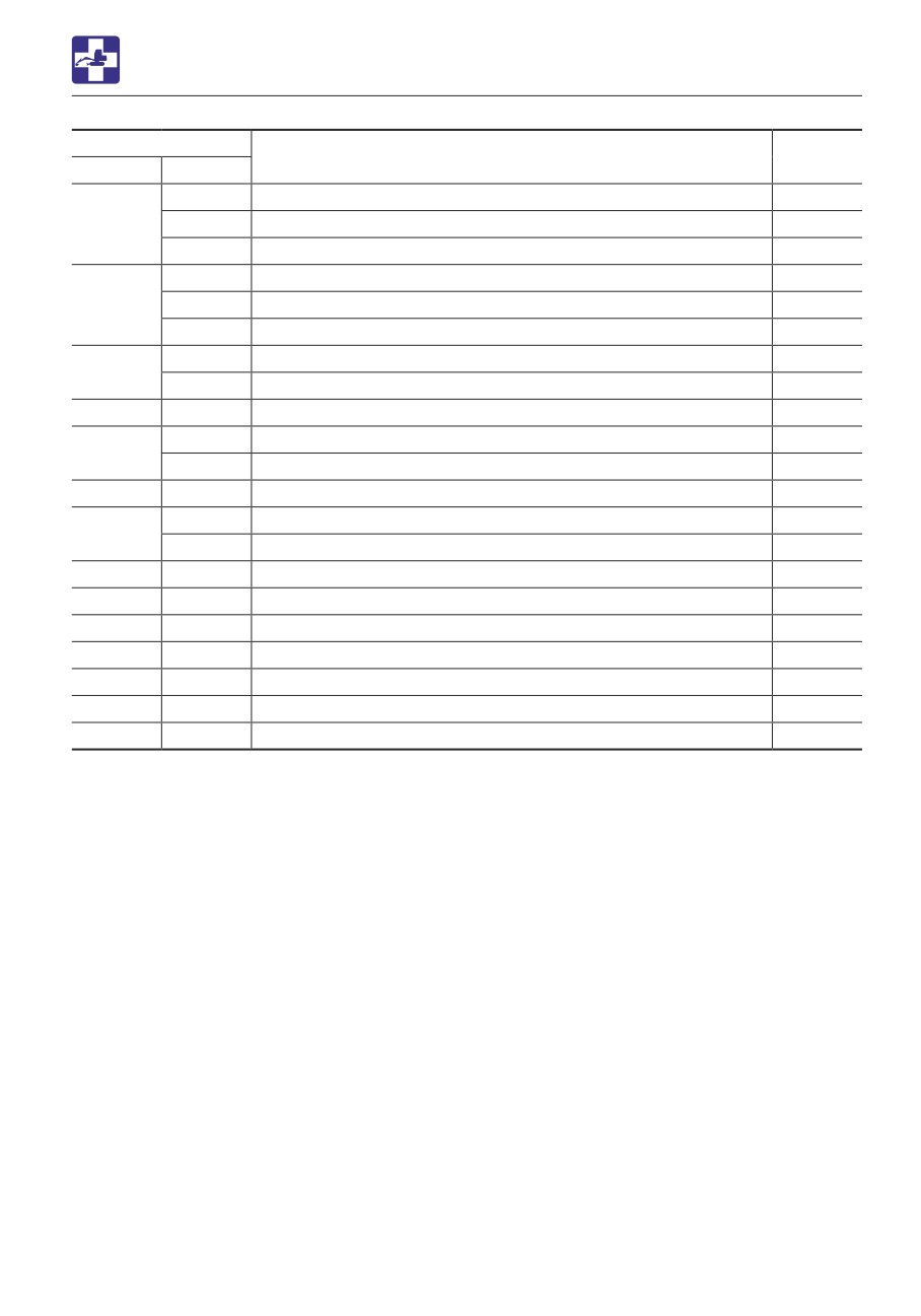
TROUBLESHOOTING
ENGINE ERROR CODE LIST
Error code
Error details
DTC
SPN
FMI
2
Intake throttle control error
P0638
10022
3
Intake throttle position sensor error (high-voltage error)
P0123
4
Intake throttle position sensor error (low-voltage error)
P0122
3
EVRV vacuum sensor error (high-voltage error)
P2528
10023
4
EVRV vacuum sensor error (low-voltage error)
P2527
20
Turbo EVRV error
P0045
3
Exhaust temp. sensor 2 error (DOC inlet) (high-voltage error)
P042D
10024
4
Exhaust temp. sensor 2 error (DOC inlet) (low-voltage error)
P042C
10025
5
DPD lamp error
P1669
0
DPD PM excessive trapping 2
P1455
10026
15
DPD PM excessive trapping
P242F
10027
0
DPD purification judgment error
P1471
0
Exhaust temp. sensor 2 high-temp. error (DOC inlet)
P042B
10028
1
Exhaust temp. sensor 2 low temp. error (DOC inlet)
P042B
10029
0
DPD regeneration timeout count too many
P2458
10030
0
Starter degradation alarm
P1500
10031
2
Starter switch error
P0512
10032
2
QR code error
P0602
10033
2
RAM error
P0604
10034
2
Wheel loader CAN timeout error
U2106
10040
19
CAN bus error (ISO-CAN)
U0001
6-19
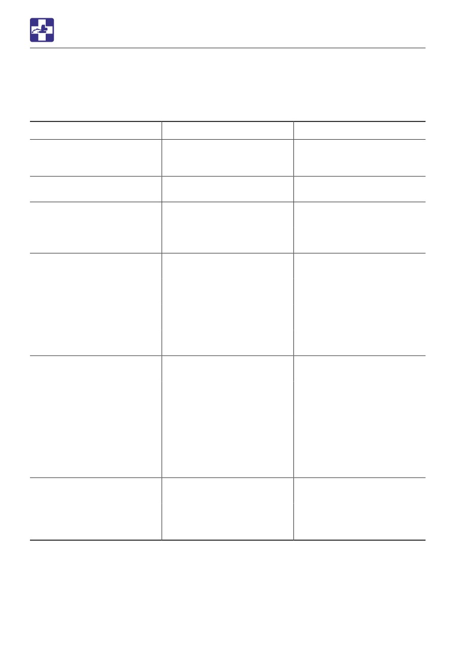
TROUBLESHOOTING
OTHER SYMPTOMS
OTHER SYMPTOMS
For symptoms not included in the table below or if the problem persists after the proper
remedies have been taken, consult your sales or service dealer.
Symptoms
Major causes
Action
Operating levers or pedals do
• Insufficient grease on the
• Grease the levers and/or
not move smoothly
operating levers or pedals.
pedals.
Refer to page 5-77.
Steering operation is not
• Steering device is faulty
• Consult your sales or
possible.
service dealer.
Operation of hoe attachment,
• Safety lock lever is raised
• Lower the safety lock lever.
dozer blade, auxiliary
Refer to page 2-48.
hydraulics, slewing or
• Fuse is blown
• Replace the fuse.
traveling is not possible.
Refer to page 6-8.
Digging force is insufficient
• Hydraulic oil level is too low
• Add up to the specified level
Refer to page 5-24.
• Hydraulic oil is too cold
• Perform the warm-up .
Refer to page 3-8 to 3-9.
• Air cleaner is clogged
• Clean the air cleaner
Refer to page 5-43.
• Hydraulic oil is not of
• Replace the hydraulic oil.
suitable type
Refer to page 5-66.
Traveling is not possible or
• Stones or foreign objects
• Remove the foreign object.
not smooth
are stuck
• Blake pedal is locked
• Release the brake pedal
lock.
Refer to page 2-50.
• Parking brake is activated
• Turn off the parking brake
switch
Refer to page 2-39.
• Release the safety lock lever
Refer to page 2-48.
Machine veers to the right/
• Stones or foreign objects
• Remove the foreign object.
left.
are stuck
• Tires have different air
• Make sure tires have the
pressure in them.
same air pressure.
Refer to page 5-26.
6-20
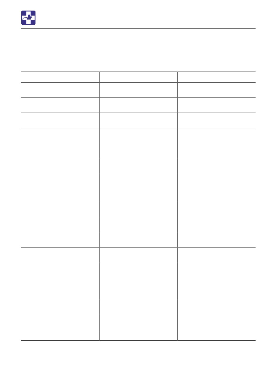
TROUBLESHOOTING
OTHER SYMPTOMS
Symptoms
Major causes
Action
Travel speed cannot be
• Fuse is blown
• Replace the fuse.
changed
Refer to page 6-8.
Slewing is not possible or not
• Insufficient grease on slew
• Add grease.
smooth.
bearing
Refer to page 5-52.
Hydraulic oil temperature is
• Hydraulic oil level is too low
• Add up to the specified level
too high
Refer to page 5-24.
Starter motor turns but
• Insufficient fuel
• Add fuel.
engine does not start
Refer to page 5-23.
• Air in fuel system
• Bleed air.
Refer to page 6-10.
• Water in fuel system
• Drain water.
Refer to page 5-35.
• Fuel is frozen
• Warm the fuel pipe with hot
water or wait until the
ambient temperature
becomes high.
• Engine control system is
• Adjust or repair (ask your
faulty.
sales or service dealer).
• Fuel line is faulty.
• Adjust or repair (ask your
sales or service dealer).
• Preheating device is faulty.
• Adjust or repair (ask your
sales or service dealer).
Engine exhaust is white or
• Excessive engine oil
• Adjust to the specified level.
bluish
Refer to page 5-21.
• Insufficient engine warm-up.
• Perform the warm-up
operation.
Refer to page 3-5.
• Engine control system is
• Adjust or repair (ask your
faulty.
sales or service dealer).
• Fuel line is faulty.
• Adjust or repair (ask your
sales or service dealer).
• Prolonged idling (approx.
• Increase the engine RPM
two hours or more)
and check for smoke.
• Poor fuel
• Replace the fuel.
6-21
TROUBLESHOOTING
OTHER SYMPTOMS
Symptoms
Major causes
Action
Engine exhaust is
• Air cleaner is clogged
• Clean the air cleaner
occasionally black
Refer to page 5-43.
• Engine control system is
• Adjust or repair (ask your
faulty.
sales or service dealer).
• Fuel line is faulty.
• Adjust or repair (ask your
sales or service dealer).
• Clogging in the exhaust line.
• Adjust or repair (ask your
sales or service dealer).
• DPD is faulty.
• Adjust or repair (ask your
sales or service dealer).
Irregular noise is produced
• Low quality fuel is being
• Replace the fuel.
from the engine
used
(combustion or mechanical
• Engine is overheating
• Refer to “If the engine
noise)
overheats” on page 6-4.
• Damage inside the muffler
• Replace the muffler.
For replacement, ask your
sales or service dealer.
6-22
TROUBLESHOOTING
LOWERING THE BOOM TO THE GROUND
1. Check that the load being lifted and the
LOWERING THE BOOM TO
machine are secure and the work area is
safe.
THE GROUND
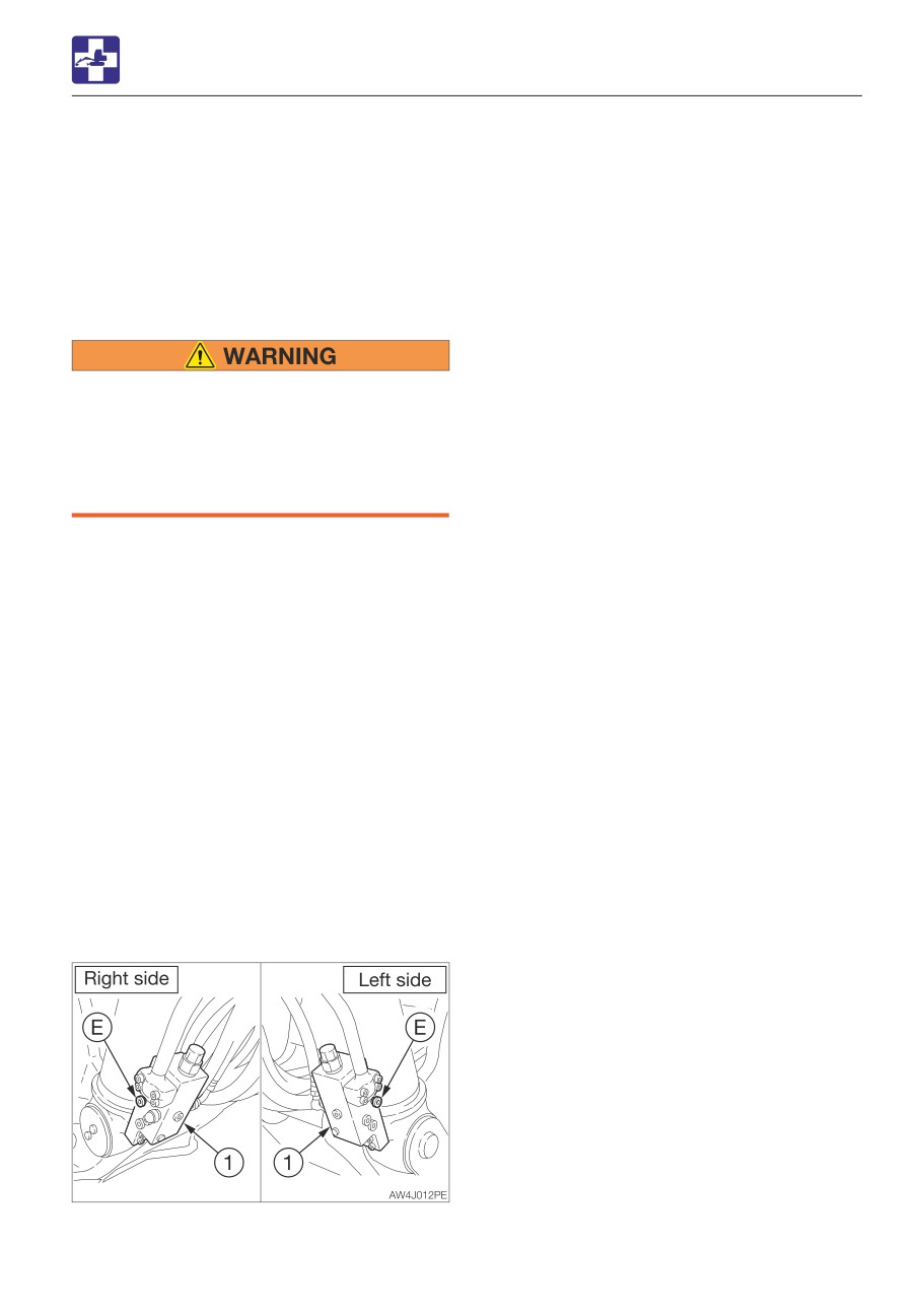
2. Place a pan under the plug (E) to catch
If the hoe attachment must be lowered to the
the used oil.
ground while the engine is stopped, use the
3. Loosen the plugs (E) slowly to lower the
following procedure.
boom. The hydraulic oil flows from the
holes of plugs (E).
Procedure
4. Check for safety and stability of the
machine.
5. Tighten the plugs (E).
• Keep away from the working area when
the hoe attachment is lowered. You may
be hit by dirt falling out of the bucket or
the hoe attachment as it drops.
• Gradually lower the boom by slowly
turning the plug on the shut-off valve.
Perform the residual pressure releasing
within 30 minutes after the engine stopping.
1. Check that the safety lock lever is in the
released position.
2. Check that the starter switch is in the ON
position.
3. Slowly push the operating lever forward to
lower the boom.
4. Check that the load being lifted and the
machine are secure and the work area is
safe.
If the boom cannot be lowered using the
above procedure, use the following
procedure.
This operation is dangerous and requires
experience. Ask your sales or service dealer
for it.
6-23
TROUBLESHOOTING
TOWING
IMPORTANT: The transmission could be
TOWING
damaged during operation if the
emergency actuator is wrongly released.
Be sure to follow the steps below to
When towing, serious injury or death
correctly release the parking brake.
could result, if performed incorrectly or
the wire rope being used is inappropriate
In case of hydraulic oil pressure failure or
or not properly inspected.
hydraulic motor failure, the emergency
• It becomes dangerous if the wire rope
actuator disconnects the reduction gear
breaks or becomes disengaged. Use a
clutch (manual release of parking brake) so
wire rope appropriate for the required
that the emergency machine towing can be
tractive force.
performed.
• Do not use a wire rope that is kinked,
twisted or otherwise damaged.
1. Stop the engine.
• Do not apply heavy loads abruptly to
2. To prevent the vehicle from moving after
the wire rope.
the parking brake is released, chock the
• Wear safety gloves when handling the
wheels.
wire rope.
• Make sure there is an operator on the
machine being towed as well as on the
machine that is towing.
• Never tow on slopes.
• Do not let anyone come near to the wire
rope while towing.
• The machine should be towed only
when it gets stuck in mud.
• Be sure to use a towing truck with
sufficient braking power.
IMPORTANT: Do not tow machines that
are not operable and no lubrication in the
transmission. Doing so could damage the
hydraulic devices due to a lack of oil
supplied. It is best to use a low loader to
transport the disabled vehicle for a long
distance.
Manually releasing the parking brake
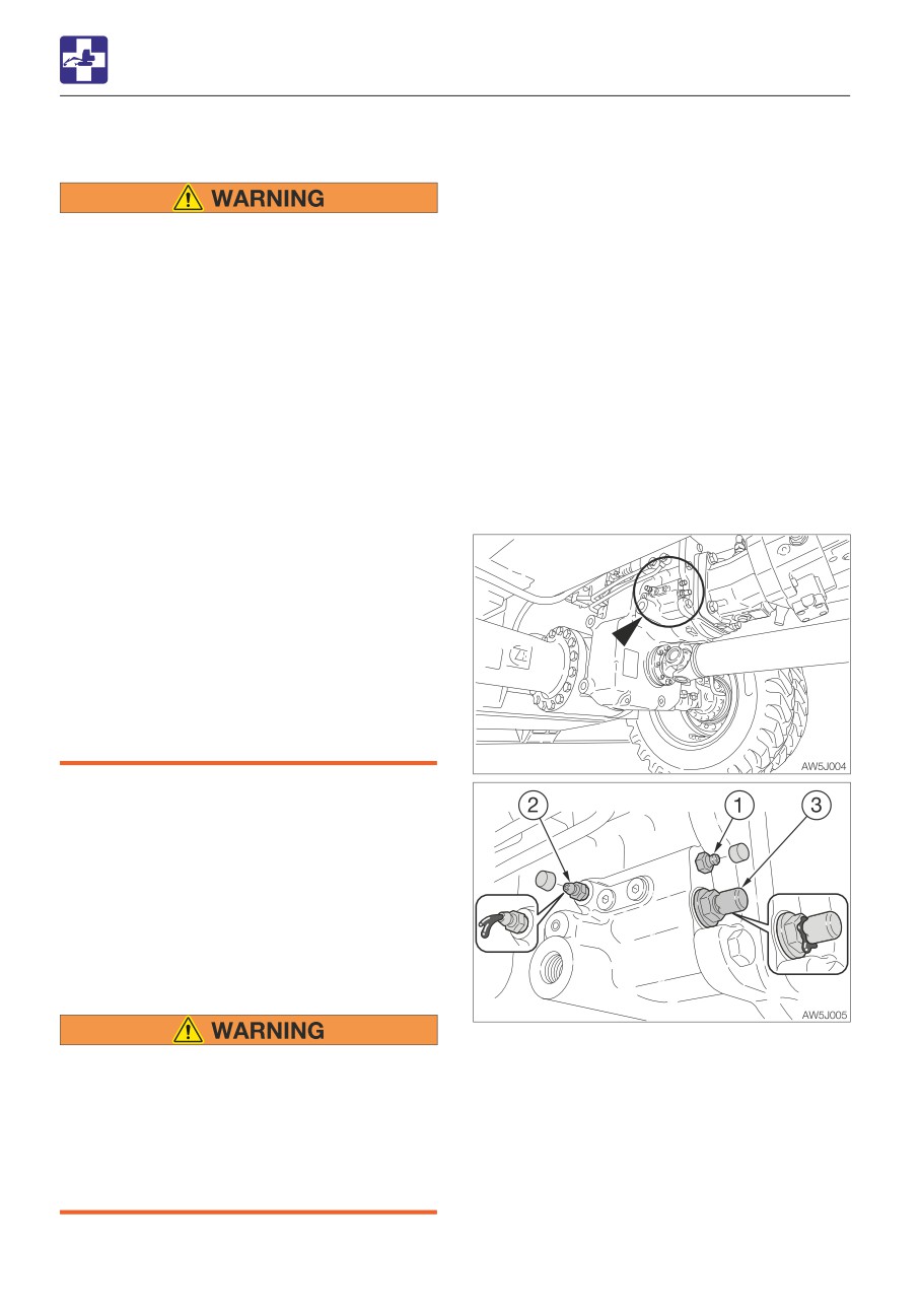
3. Remove the cap, and then inject grease
• Brake malfunction can cause death or
through the grease fitting (1) with the
injury. Do not operate the machine with
grease gun.
a faulty brake. Resolve the problems
4. The vehicle towing can be performed
before trying to operate the machine.
when it is visually confirmed that the
• Be sure to secure the vehicle by
grease comes out of the pressure relief
chocking the wheels before releasing
valve of the emergency actuator (3).
the parking brake.
6-24
TROUBLESHOOTING
TOWING
Towing the machine
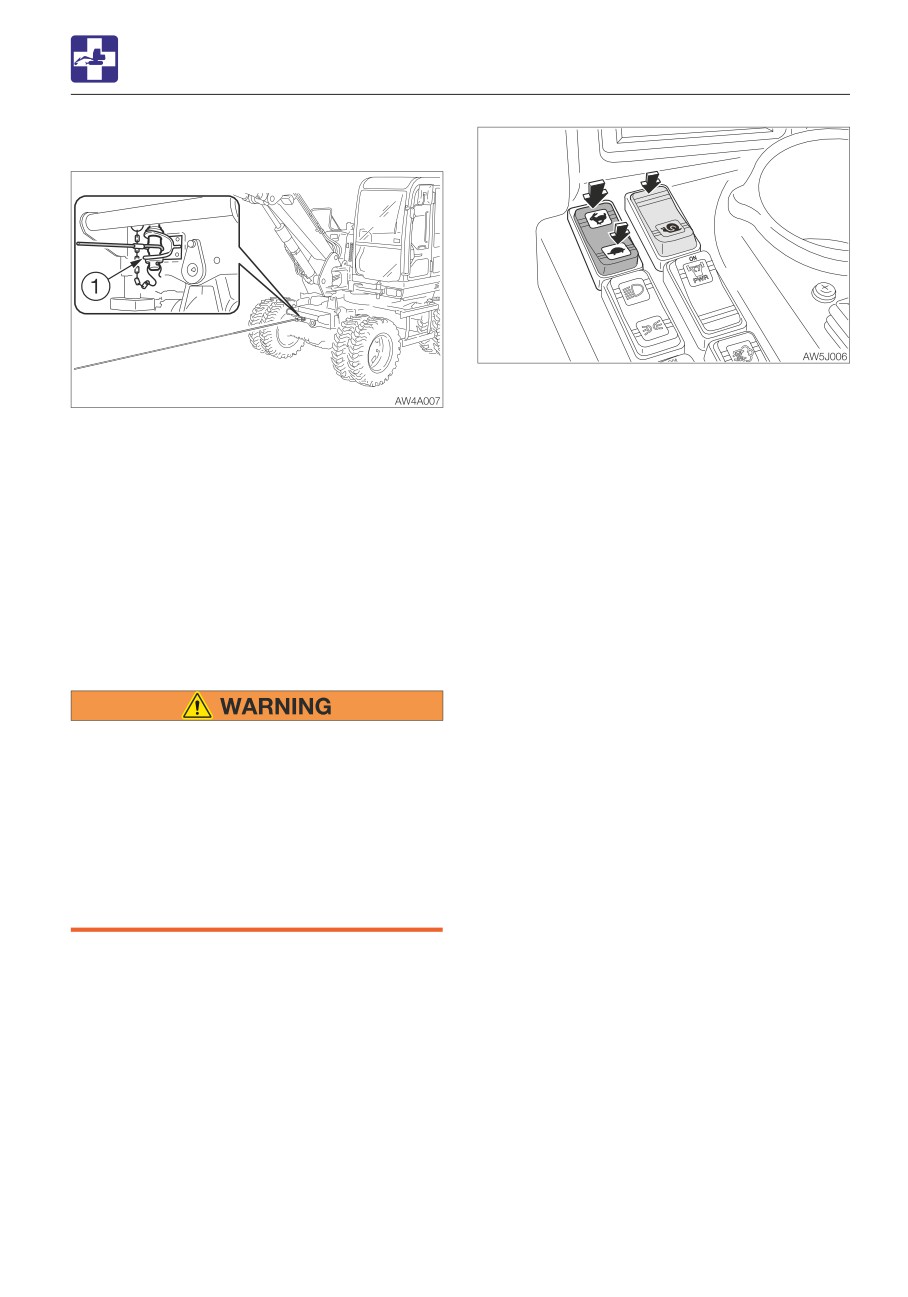
7. Depress the “Hare” symbol on low/high-
speed travel switch to change to the
1. Attach the wire rope to the shackle (1).
high-speed travel gear.
2. Make sure that the wire rope is horizontal
(Creeping travel switch: OFF)
and is lined up straight with the travel
8. Alternately switch between the low-speed
frame.
and the high-speed until the grease is
3. Move the machine to tension the wire
completely removed from the grease
rope.
discharge valve (2). Be sure to thoroughly
4. Move the machine slowly and tow.
remove the grease even in cold climates
· Towing speed: 2 km/h(1.24 mph) or less
when it becomes harder to discharge due
· Towing distance: 5 km (3.1 miles) or less
to the hardened/thickened grease.
9. Raise the safety lock lever to the lock
Reactivating the parking brake
position.
10. Stop the engine.
11. Tighten the grease discharge valve (2),
and then attach the cap.
• Completely drain the grease injected.
12. Remove the wheel chocks.
Otherwise, it will be dangerous to travel;
the parking brake cannot be operated
due to the slipping clutch. Also, the
clutch could be damaged due to the
heat generated by the slipping clutch.
• Be sure to secure the vehicle by
chocking the wheels before reactivating
the parking brake.
1. Park the machine on a flat, rigid and safe
ground. Stop the engine.
2. To immobilize the vehicle, chock the
wheels.
3. Remove the cap on the grease discharge
valve (2), and then loosen the valve to
open it, in order to release pressure and
activate the parking brake.
4. Depress the brake pedal all the way down
to lock it.
5. Start the engine.
6. Lower the safety lock lever to the unlock
position.
6-25
TROUBLESHOOTING
IF THE CAB IS DAMAGED
IF THE CAB IS DAMAGED
Immediately replace the damaged cab.
Serious injury or death may occur if the
machine is operated with damaged cab.
Do not operate the machine until the
replacement is complete. Do not try to
repair the damaged cab by welding.
Doing so could endanger the safety of the
cab.
Cab part number: 05786-05100
6-26
SPECIFICATIONS
7-1
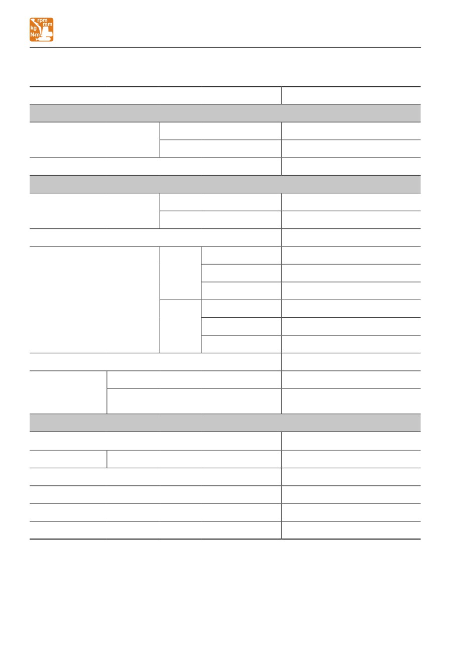
SPECIFICATIONS
BASIC SPECIFICATIONS
BASIC SPECIFICATIONS
Type
2-Piece boom
MASS
Machine with an Outriggers
15070 (33225)
Operating mass***
kg (lb)
Equipped with a rear blade
14570 (32120)
Maximum Operating mass**
kg (lb)
16000 (35274)
PERFORMANCE
Heaped
0.505
(17.83)
Bucket capacity
m3 (cu. ft.)
(Standard bucket)
Struck
0.369
(13.02)
Slew speed
min-1 (rpm)
10.8
(10.8)
Creep
0 to 4.3 (2.67)
Forward
Low-speed travel
0 to 8.5 (5.28)
High-speed travel
0 to 29.2 (18.14)/ 0 to 20 (12.43)*
km/h
Travel speed
(mph)
Creep
0 to 4.3 (2.67)
Reverse
Low-speed travel
0 to 8.5 (5.28)
High-speed travel
0 to 29.2 (18.14)/ 0 to 20 (12.43)*
Gradeability
(degrees)
35
Sound power level
LWA 99
Noise level dB (A)
Emission sound pressure level at the
LpA 75
operator’s position (ISO 6396,2008:)
ENGINE
Manufacturer and model
ISUZU AM-4JJ1XZSB-03
Rated output
Net (ISO 14396)
kW/min-1 (hp/rpm)
95.0/2200 (127.4/2200)
Displacement
ml (cu.in.)
2999 (183)
Starter
V-kW
24 - 4.0
Alternator
V-kW
24 - 1.2
Battery (IEC 60095-1)
V-A·h
12 - 104 X 2
: Option
** : Maximum operating mass:
Optional parts can be added until the total mass of the machine reaches this mass value.
***: Equipped with fourth auxiliary hydraulic lines (15kg or 33lb.).
7-2
MEMO
7-3
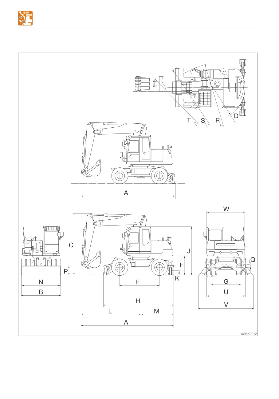
SPECIFICATIONS
MACHINE DIMENSIONS
MACHINE DIMENSIONS
7-4
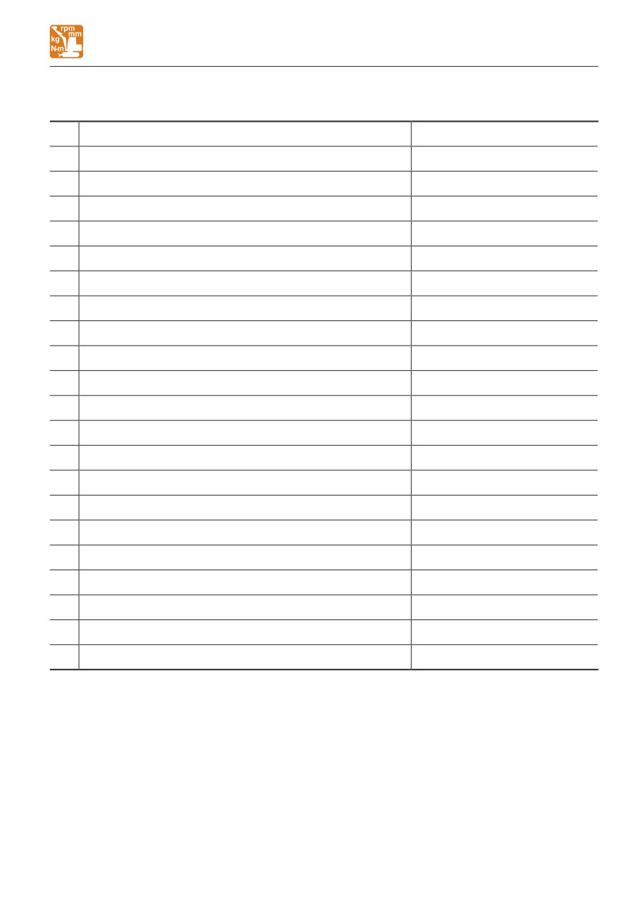
SPECIFICATIONS
MACHINE DIMENSIONS
Unit: mm (inch)
Item
2-Piece boom
A
Overall length
6030 (237.5)*/ 6085 (239.5)
B
Overall width
2525 (99.4)
C
Overall height
3985 (156.9)
D
Slew radius
2065 (81.4)
E
Clearance height under upperstructure
1245 (49.0)
F
Wheel base
2565 (101)
G
Tread
1945 (76.5)
H
Overall length of undercarriage
4600 (181.1) *
J
Overall height of base machine
3130 (123.1)
K
Ground clearance of undercarriage
275 (10.8) *
L
Front distance to axis of rotation
3860 (152.0)
M
Rear distance to axis of rotation
2170 (85.4)
N
Dozer blade width
2480 (97.6)
P
Dozer blade height
600 (23.6)
Q
Swing angle of axles
7.5°
R
Minimum turning radius (Tire)
6380 (251.2)
S
Minimum turning radius (Dozer blade)
7025 (276.5)
T
Outside machine clearance radius
7295 (287.2)
U
Width of pad outrigger retracted
2500 (98.4) *
V
Width of pad outrigger extended
3555 (140.0) *
W
Overall width of upperstructure
2460 (96.9)
*: With an outrigger
7-5
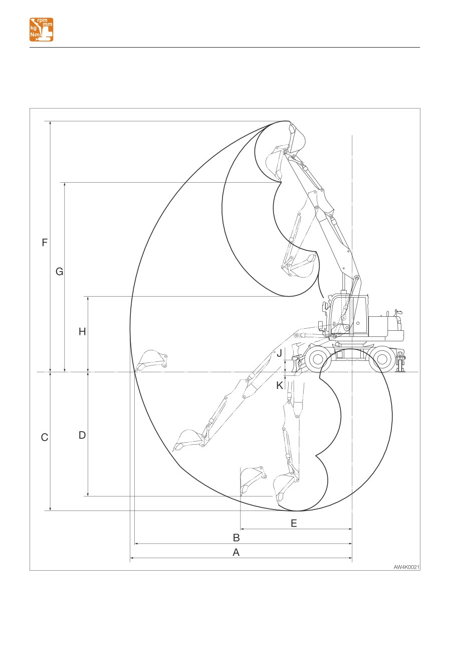
SPECIFICATIONS
OPERATING RANGES
OPERATING RANGES
2-Piece boom
7-6
SPECIFICATIONS
OPERATING RANGES
2-Piece boom
Unit: mm (inch)
Item
2570 mm (101.2 in) arm
A
Maximum reach
8885 (349.8)
B
Maximum reach at ground reference plane
8705 (342.8)
C
Maximum digging depth
5555 (218.7)
D
Maximum vertical digging depth
4965 (195.5)
E
Reach at maximum vertical digging depth
4480 (176.4)
F
Maximum height of cutting edge
10030 (394.8)
G
Maximum dumping height
7580 (298.3)
H
Minimum dumping height
3020 (118.8)
J
Dozer blade maximum lifting
480 (18.9)
K
Dozer blade maximum lowering
140 (5.6)
7-7
MEMO
7-8