Takeuchi compact excavator TB210R (Serial No. 211000004~). Operators Manual (2019) - page 5
TROUBLESHOOTING
IF THE BATTERY GOES DEAD
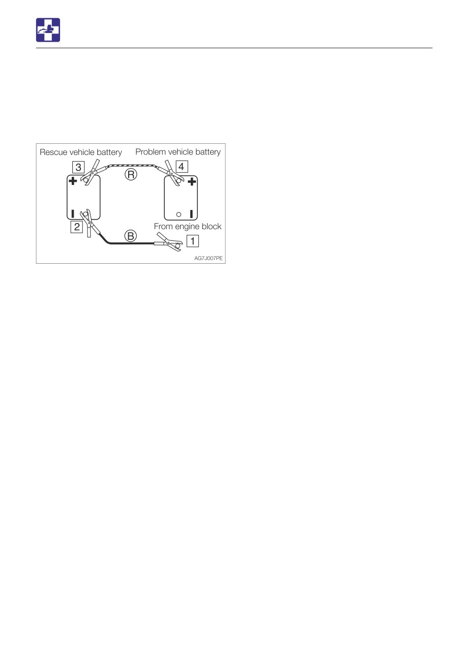
Disconnecting the jumper cables
Once the dead machine is successfully
running, remove the jumper cables by
following the same steps as for connection in
the reverse order.
1. Disconnect the clip of jumper cable (B)
from the engine block of the dead
machine.
2. Disconnect the other clip of jumper cable
(B) from the negative (-) battery terminal of
the booster vehicle.
3. Disconnect the clip of jumper cable (R)
from the positive (+) battery terminal of the
booster vehicle.
4. Disconnect the clip of jumper cable (R)
from the positive (+) battery terminal of the
dead machine.
Recharging
Ask your sales or service dealer for
recharging the dead battery.
6-5
TROUBLESHOOTING
IF A FUSE BLOWS
Fuse layout and circuits protected
IF A FUSE BLOWS
If a light does not come on or the electrical
Protected
system does not work, a fuse may be blown.
Capacity
Symbol
circuit
Inspect the fuses.
10A
Horn
INSPECTING AND REPLACING THE FUSE
Engine stop
30A
solenoid
20A
Boom light
If the fuse blows again soon after
10A
Hour meter
replacement, then the electric system is
likely faulty. It may pose a fire hazard if
15A
Lever lock
not properly repaired. Contact your sales
3A
Feed pump
or service dealer for advice.
1. Turn the starter key to the OFF position to
stop the engine.
2. Open the engine hood.
3. Open the fuse box cover (1).
4. Check for any blown fuses.
5. If a fuse is blown, replace it with a spare
fuse of the same capacity.
6-6
TROUBLESHOOTING
IF A FUSE BLOWS
INSPECTING THE FUSIBLE LINK
If the machine is not turned on after turning
the starter switch to the ON position, the
cartridge type fusible link (1) is likely blown.
Open the engine hood and inspect. If the
fusible link is blown, please contact your
sales or service dealer.
Note: Fusible links are large type fuses used
in high current applications. Like a regular
fuse, they act as fuses by protecting the
electric components and wirings from
damage caused by excessive current draw.
6-7
TROUBLESHOOTING
RESTARTING AFTER ADDING FUEL
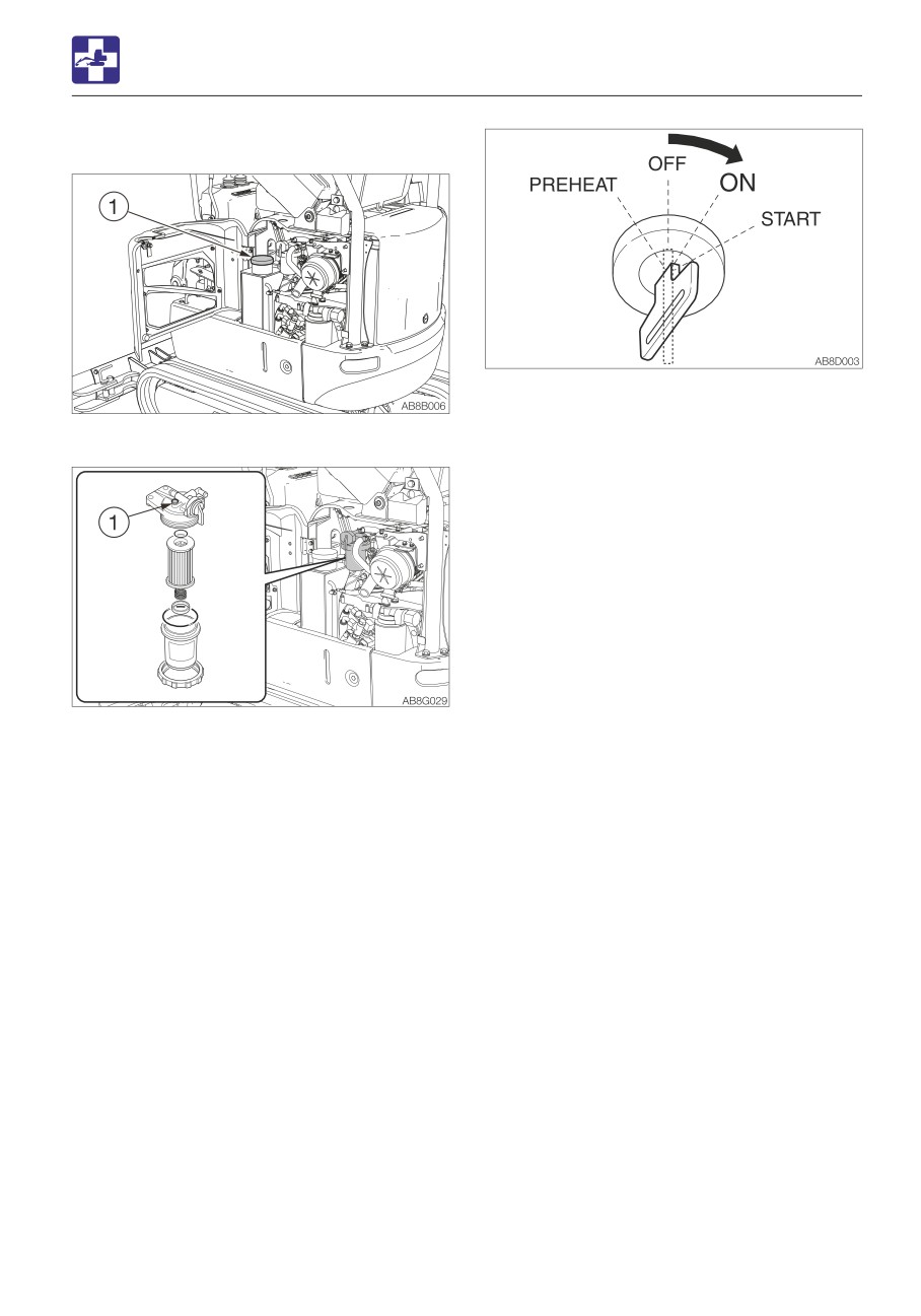
For machines without a pre-fuel filter
RESTARTING AFTER ADDING
FUEL
BLEEDING AIR FROM THE FUEL SYSTEM
IMPORTANT: NEVER use the starter
motor to crank the engine in order to
prime the fuel system. This may cause the
starter motor to overheat and damage the
coils, pinion gear and/or ring gear.
IMPORTANT: If the engine stalls due to
fuel shortage, add fuel, turn the key to the
ON position for 60 seconds, and then turn
1. Add fuel.
it to the START position. Running the
starter for a long time before there is
enough fuel is going through can cause
the starter to fail.
2. Turn the starter key to the ON position and
hold it for about 60 seconds.
6-8
TROUBLESHOOTING
RESTARTING AFTER ADDING FUEL
For machines with a pre-fuel filter
3. Turn the starter key to the ON position and
hold it for about 60 seconds.
1. Add fuel.
The automatic air bleeder bleeds air from
the fuel system.
Note: Air in the fuel system causes the
engine to fail to start or to have other
problems. Always bleed air when the fuel
tank is emptied or when there is air in the fuel
system.
2. Loosen the air-bleeding bolt (1).
6-9
TROUBLESHOOTING
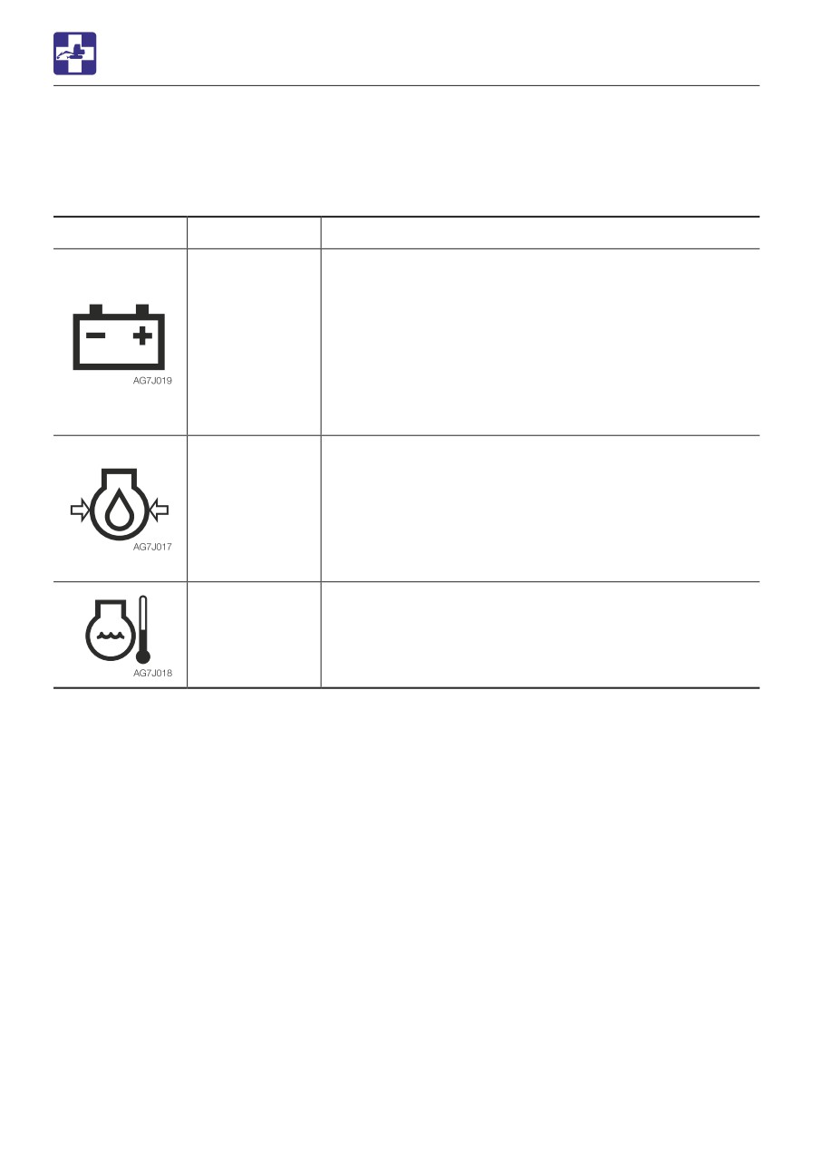
IF A WARNING LAMP LIGHTS UP
IF A WARNING LAMP LIGHTS UP
If a warning lamp lights up during operation, park the machine in a safe place and perform the
procedures described below.
Warning lamp
Lamp name
Causes and remedies
Battery charge
There is a problem with the fan belt or charger.
warning lamp
Inspect the fan belt for slack or breakage and adjust as
necessary.
If the lamp lights up even after maintenance, there is
likely a problem with the charger. Consult your sales or
service dealer for help.
Refer to “Inspecting and adjusting the fan belt” on page
5-24.
Engine oil
There is a problem in the engine lubrication system.
pressure
warning lamp
Check the engine oil level. If the lamp lights up when the
level is normal or even after replenishment of oil, consult
your sales or service dealer for help.
Refer to “Inspecting and replenishing the engine oil” on
page 5-17.
Coolant
The coolant temperature is too high and the engine is
temperature
overheating.
warning lamp
Refer to “If the engine overheats” on page 6-3.
6-10

TROUBLESHOOTING
OTHER SYMPTOMS
OTHER SYMPTOMS
For symptoms not included in the table below or if the problem persists after the proper
remedies have been taken, consult your sales or service dealer.
Symptoms
Major causes
Remedies
Left and right operating levers
• Insufficient grease on the
• Grease the levers.
do not move smoothly
left and right operating
Refer to page 5-48.
levers
Throttle lever does not move
• Wire is stretched too lose
• Adjust or replace (ask your
smoothly
sales or service dealer).
Hoe attachment, slewing or
• Safety lock lever is raised
• Lower (release) the safety
traveling operation not
(locked)
lock lever.
possible
Refer to page 2-14.
• Fuse is blown
• Replace the fuse.
Refer to page 6-6.
• Adjustment of travel lock is
• Adjust the travel lock (ask
faulty
your sales or service dealer).
Digging force is insufficient
• Hydraulic oil level too low
• Add to the specified level.
Refer to page 5-19.
• Hydraulic oil is not warm
• Perform the warm-up.
enough
Refer to page 3-8.
• Air cleaner is clogged
• Clean the air cleaner.
Refer to page 5-34.
• Hydraulic oil is not of
• Replace the hydraulic oil.
suitable type
Refer to page 5-43.
Traveling is not possible or
• Stones or foreign objects
• Remove the foreign object.
not smooth
are stuck
Machine veers to the right/left
• Stones or foreign objects
• Remove the foreign object.
are stuck
• Faulty crawler tension
• Adjust the crawler to the
adjustment
prescribed tension.
Refer to page 5-26.
Travel speed cannot be
• Fuse is blown
• Replace the fuse.
changed
Refer to page 6-6.
6-11

TROUBLESHOOTING
OTHER SYMPTOMS
Symptoms
Major causes
Remedies
Slewing is not possible or not
• Slew lock lever lock is not
• Release the slew lock lever
smooth
released
• Insufficient grease on slew
• Grease the bearing.
bearing
Refer to page 5-28.
Hydraulic oil temperature is
• Hydraulic oil level too low
• Add up to the specified
too high
level.
Refer to page 5-19.
Starter motor turns but
• Insufficient fuel
• Add fuel.
engine does not start
Refer to page 5-18.
• Air in fuel system
• Bleed air.
Refer to page 6-8.
• Water in fuel system
• Drain water.
Refer to page 5-29.
• Fuel is frozen.
• Warm the fuel pipe with hot
water or wait until the
ambient temperature
becomes high.
• Engine control system is
• Adjust or repair (ask your
faulty.
sales or service dealer).
• Fuel line is faulty.
• Adjust or repair (ask your
sales or service dealer).
• Preheating device is faulty.
• Adjust or repair (ask your
sales or service dealer).
Crawlers come off
• Crawlers too loose
• Increase the tension.
Refer to page 5-26.
6-12

TROUBLESHOOTING
OTHER SYMPTOMS
Symptoms
Major causes
Remedies
Engine exhaust is white or
• Excessive engine oil
• Adjust to the specified level.
bluish
Refer to page 5-17.
• Insufficient engine warm-up.
• Perform the warm-up
operation.
Refer to page 3-5.
• Engine control system is
• Adjust or repair (ask your
faulty.
sales or service dealer).
• Fuel line is faulty.
• Adjust or repair (ask your
sales or service dealer).
• Prolonged idling (approx.
• Increase the engine RPM
two hours or more)
and check for smoke.
• Poor fuel
• Replace the fuel.
Engine exhaust is
• Air cleaner is clogged
• Clean the air cleaner.
occasionally black
Refer to page 5-34.
• Engine control system is
• Adjust or repair (ask your
faulty.
sales or service dealer).
• Fuel line is faulty.
• Adjust or repair (ask your
sales or service dealer).
• Clogging in the exhaust line.
• Adjust or repair (ask your
sales or service dealer).
Irregular noise is produced
• Low quality fuel is being
• Replace the fuel.
from the engine
used
(combustion or mechanical
• Engine is overheating
• Refer to “If the engine
noise)
overheats” on page 6-3.
• Damage inside the muffler
• Replace the muffler.
For replacement, ask your
sales or service dealer.
6-13
TROUBLESHOOTING
LOWERING THE BOOM TO THE GROUND
• Do not loosen or remove the hoses not
LOWERING THE BOOM TO
located in the specified places. Oil may
spurt out if wrongly handled.
THE GROUND
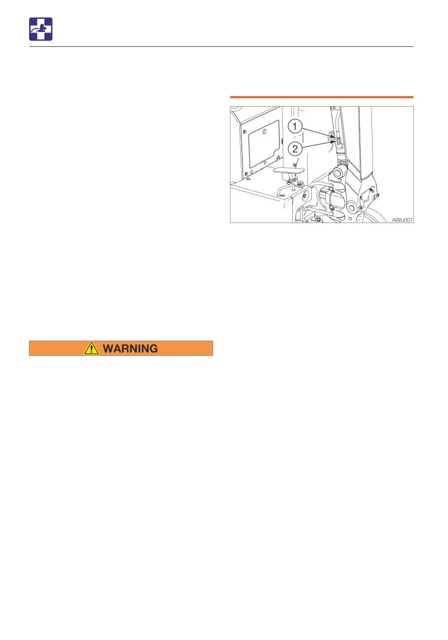
If the hoe attachment must be lowered to the
ground while the engine is stopped, use the
following procedure.
Procedure 1
(machines with an accumulator)
Perform this operation within 10 minutes
after the engine stopping.
1. Sit at the operator’s seat.
2. Turn the starter switch to the ON position.
3. Lower the safety lock lever to the unlock
position
1. Place a pan under the hose to catch the
4. Slowly push the operating lever forward to
waste oil.
lower the boom.
2. Hold the hose fitting (1) with a wrench and
slowly loosen the hose nut (2) with another
Procedure 2
wrench.
(machines without an accumulator)
3. The oil in the boom cylinder is drained and
This operation is dangerous and requires
the hoe attachment is lowered.
experience. Ask your sales or service dealer
4. After the hoe attachment is lowered to the
for it.
ground, check the safety and stability of
the machine.
5. Hold the hose fitting (1) with a wrench and
tighten the hose nut (2) with another
• Stop the engine and allow the machine
wrench.
to cool down before performing
· Tightening torque: 24.5 to 29.4 N·m
maintenance.
(18.1 to 21.6 ft-lb.)
· The engine and the hydraulic system
and many other parts of the machine
are hot immediately after the engine is
stopped. Touching these parts will
cause burns.
· The hydraulic oil is also hot and under
high pressure immediately after the
engine is stopped.
Be careful when loosening the caps or
plugs. Working on the machine under
these conditions could result in burns
or injuries due to the hot oil spurting
out.
• Keep away from the working area when
the hoe attachment is lowered. You may
be hit by dirt falling out of the bucket or
the hoe attachment as it drops.
• Slowly turn the hose nut and lower the
boom at a slow pace.
6-14
TROUBLESHOOTING
TOWING
Towing the machine
TOWING
Use the procedure described below to tow
heavy objects or the machine itself if it
should get stuck in the mud and not be able
When towing, serious injury or death
to get out on its own.
could result, if performed incorrectly or
the wire rope being used is inappropriate
or not properly inspected.
• It becomes dangerous if the wire rope
breaks or becomes disengaged. Use a
wire rope appropriate for the required
tractive force.
• Do not use a wire rope that is kinked,
twisted or otherwise damaged.
• Do not apply heavy loads abruptly to
the wire rope.
• Wear safety gloves when handling the
wire rope.
• Permissible force: 16.9 KN (3800 lbf)
• Make sure there is an operator on the
machine being towed as well as on the
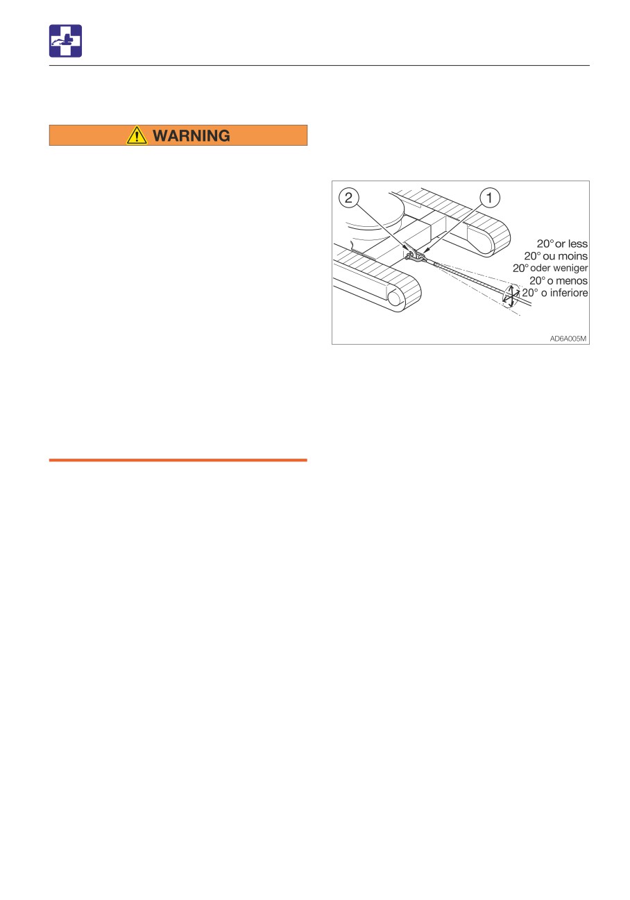
1. Attach the wire rope to the shackle (1).
machine that is towing.
2. Fasten the shackle (1) to the towing holes
• Never tow on slopes.
(2).
• Do not let anyone come near to the wire
3. Make sure that the wire rope is at a cone
rope while towing.
angle of 20° or less to the travel frame.
4. Move the machine to tension the wire
IMPORTANT: Do not tow a machine if its
rope.
engine does not start or if the machine
5. Move the machine at a low speed of 2
does not run. Doing so could damage the
km/h (1.24 mph) or less to a place
machine being towed.
(convenient location for repair) a short
IMPORTANT: Be sure to follow the steps
distance from the site.
below closely when using the towing hole
to tow. Failure to heed even one of the
steps may cause damage to the towing
hole or other parts of the frame.
6-15
TROUBLESHOOTING
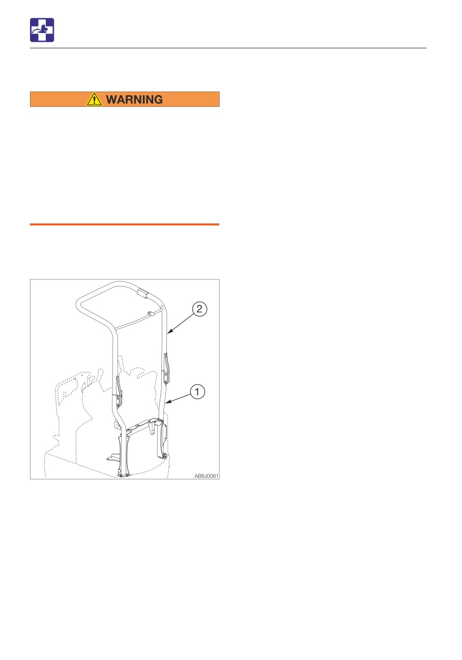
IF THE CANOPY IS DAMAGED
IF THE CANOPY IS DAMAGED
Immediately replace the damaged
canopy.
Serious injury or death could occur if the
machine is operated with damaged
canopy.
Do not operate the machine until the
replacement is complete. Do not try to
repair the damaged canopy by welding.
Doing so could endanger the safety of the
canopy.
Canopy parts No.(1) 03284-00035
Canopy parts No.(2) 03284-00010
6-16
SPECIFICATIONS
7-1
SPECIFICATIONS
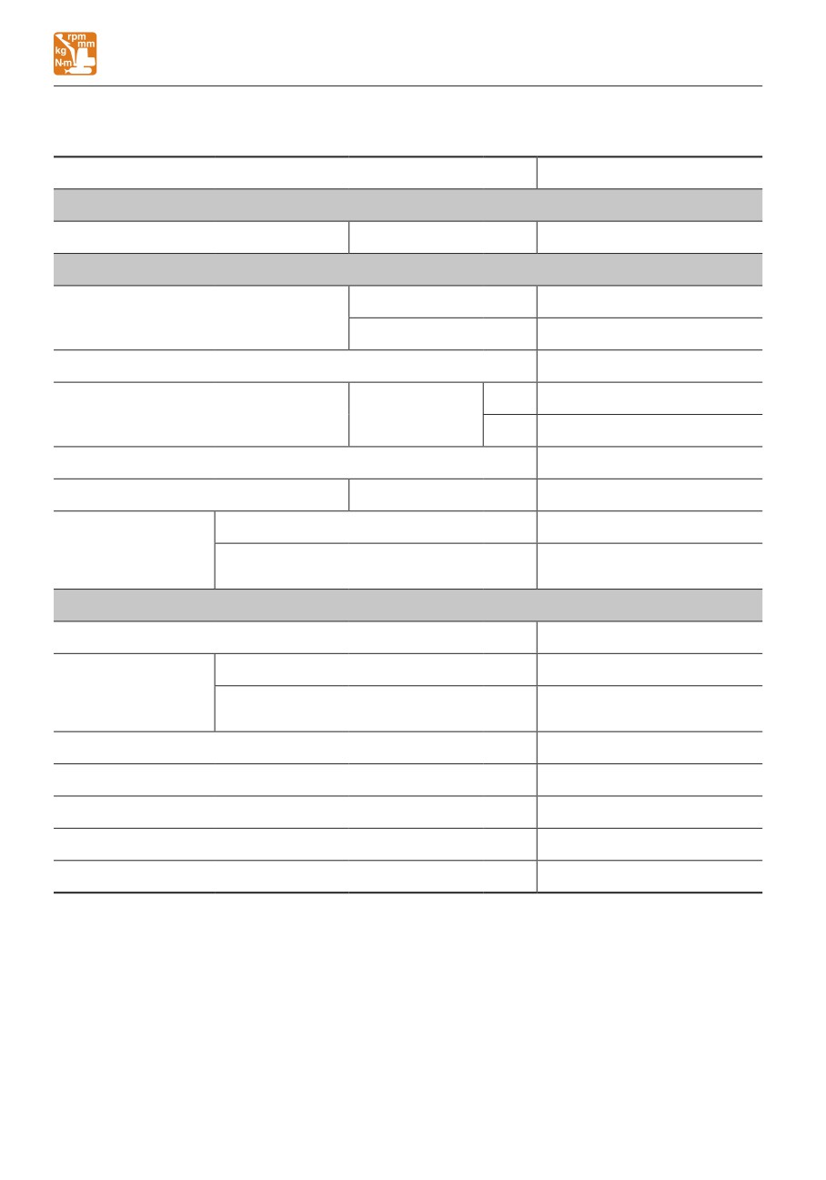
BASIC SPECIFICATIONS
BASIC SPECIFICATIONS
Type
Canopy
MASS
Operating mass
kg (lb)
Rubber crawlers
1150 (2535)
PERFORMANCE
Heaped
0.022
(0.76)
Bucket capacity
m3 (cu. ft.)
(Standard bucket)
Struck
0.016
(0.57)
Slew speed
min-1 (rpm)
10 (10)
1st
2.0
(1.24)
Travel speed
km/h (mph)
Rubber crawlers
2nd
3.7
(2.30)
Gradeability
(degrees)
15
Ground pressure
kPa (psi)
Rubber crawlers
28.0
(4.06)
Sound power level
LWA 91
Noise level dB (A)
Emission sound pressure level at the
LpA 77
operator’s position (ISO 6396, 2008:)
ENGINE
Manufacturer and model
Kubota D722-E4B
Net (ISO14396)
kW/min-1 (hp/rpm)
8.8/2200 (11.8/2200)
Rated output
Net (ISO9249 /
kW/min-1 (hp/rpm)
8.7/2200 (11.7/2200)
SAEJ1349)
Displacement
ml (cu.in.)
719 (43.9)
Amount of CO2 emission*
g/kWh
1019.8
Starter
V-kW
12-1.2
Alternator
V-kW
12-0.48
Battery (IEC 60095-1)
V-A·h
12-36
*: The amount of CO2 emission refers to the value obtained by testing the parent engine
representing the engine type (engine family member) being used; it shall not guarantee the
performance of the machine.
7-2
MEMO
7-3
SPECIFICATIONS
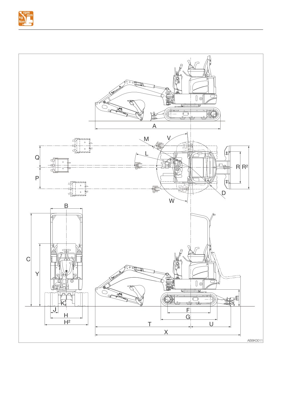
MACHINE DIMENSIONS
MACHINE DIMENSIONS
7-4

SPECIFICATIONS
MACHINE DIMENSIONS
Unit: mm (inch)
Item
Rubber crawlers
A
Overall length
2955 (116.3)
B
Upperstructure overall width
750 (29.5)
C
Overall height
2190 (86.2)
D
Slew radius
610 (24.0)
E
Clearance height under upperstructure
395 (15.6)
F
Crawler base
1005 (39.6)
G
Crawler overall length
1325 (52.2)
H
Crawler overall width (narrow)
750 (29.5)
H2
Crawler overall width (wide)
1020 (40.2)
J
Crawler shoe width
180 (7.1)
K
Ground clearance of undercarriage
160 (6.3)
L
Minimum radius of equipment and attachment
1320 (52.0)
M
Minimum radius of equipment at maximum front offset
980 (38.6)
P
Offset distance of bucket (Right swing)
505 (19.9)
Q
Offset distance of bucket (Left swing)
510 (20.1)
R
Dozer blade width (narrow)
750 (29.5)
R2
Dozer blade width (wide)
1020 (40.2)
S
Dozer blade height
200 (7.9)
T
Front distance to axis of rotation
2245 (88.5)
U
Dozer blade distance to axis of rotation
930 (36.6)
V
Boom swing angle (Right)
85°
W
Boom swing angle (Left)
85°
X
Overall length (canopy is folded)
3415 (134.4)
Y
Overall height (canopy is folded)
1475 (58.1)
7-5
SPECIFICATIONS
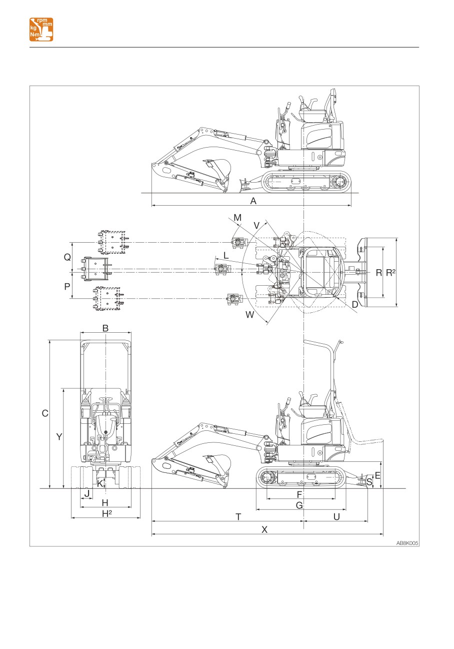
MACHINE DIMENSIONS
Limited boom swing angle type
7-6

SPECIFICATIONS
MACHINE DIMENSIONS
Limited boom swing angle type
Unit: mm (inch)
Item
Rubber crawlers
A
Overall length
2955 (116.3)
B
Upperstructure overall width
750 (29.5)
C
Overall height
2190 (86.2)
D
Slew radius
610 (24.0)
E
Clearance height under upperstructure
395 (15.6)
F
Crawler base
1005 (39.6)
G
Crawler overall length
1325 (52.2)
H
Crawler overall width (narrow)
750 (29.5)
H2
Crawler overall width (wide)
1020 (40.2)
J
Crawler shoe width
180 (7.1)
K
Ground clearance of undercarriage
160 (6.3)
L
Minimum radius of equipment and attachment
1320 (52.0)
M
Minimum radius of equipment at maximum front offset
1165 (45.9)
P
Offset distance of bucket (Right swing)
390 (15.3)
Q
Offset distance of bucket (Left swing)
440 (17.4)
R
Dozer blade width (narrow)
750 (29.5)
R2
Dozer blade width (wide)
1020 (40.2)
S
Dozer blade height
200 (7.9)
T
Front distance to axis of rotation
2245 (88.5)
U
Dozer blade distance to axis of rotation
930 (36.6)
V
Boom swing angle (Right)
55°
W
Boom swing angle (Left)
55°
X
Overall length (canopy is folded)
3415 (134.4)
Y
Overall height (canopy is folded)
1475 (58.1)
7-7
SPECIFICATIONS
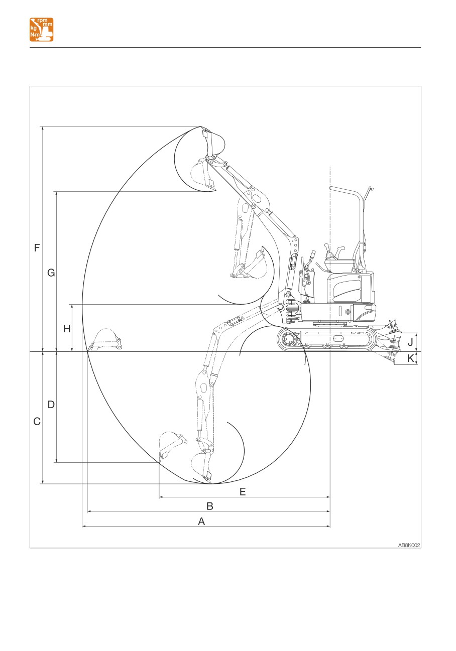
OPERATING RANGES
OPERATING RANGES
7-8

SPECIFICATIONS
OPERATING RANGES
Unit: mm (inch)
Item
Rubber crawlers
A
Maximum reach
3285 (129.3)
B
Maximum reach at ground reference plane
3220 (126.8)
C
Maximum digging depth
1755 (69.1)
D
Maximum vertical digging depth
1475 (58.1)
E
Reach at maximum vertical digging depth
2265 (89.2)
F
Maximum height of cutting edge
2985 (117.5)
G
Maximum dumping height
2120 (83.5)
H
Minimum dumping height
625 (24.6)
J
Dozer blade maximum lifting
250 (9.8)
K
Dozer blade maximum lowering
175 (6.9)
7-9
MEMO
7-10
SPECIFICATIONS
LIFTING CAPACITIES
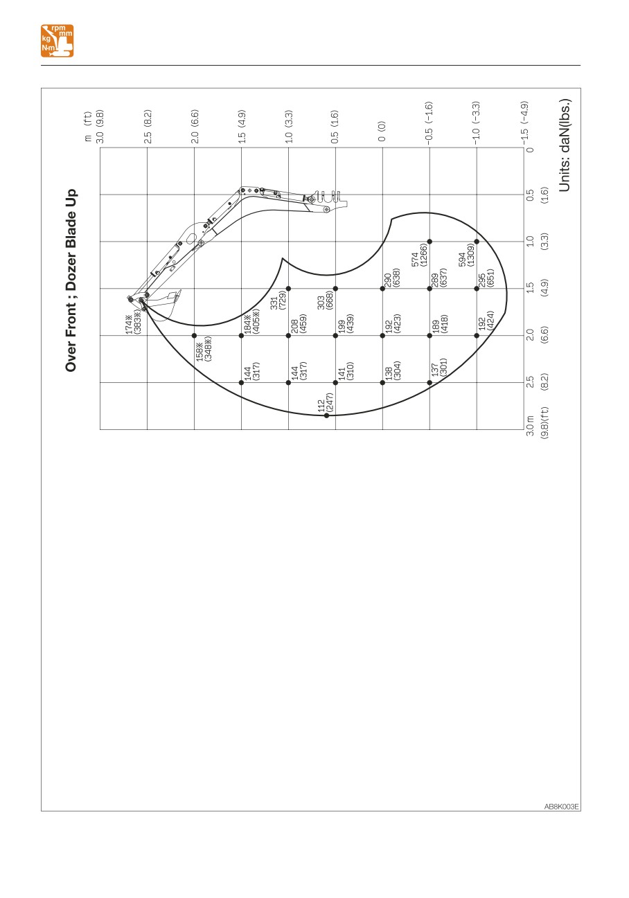
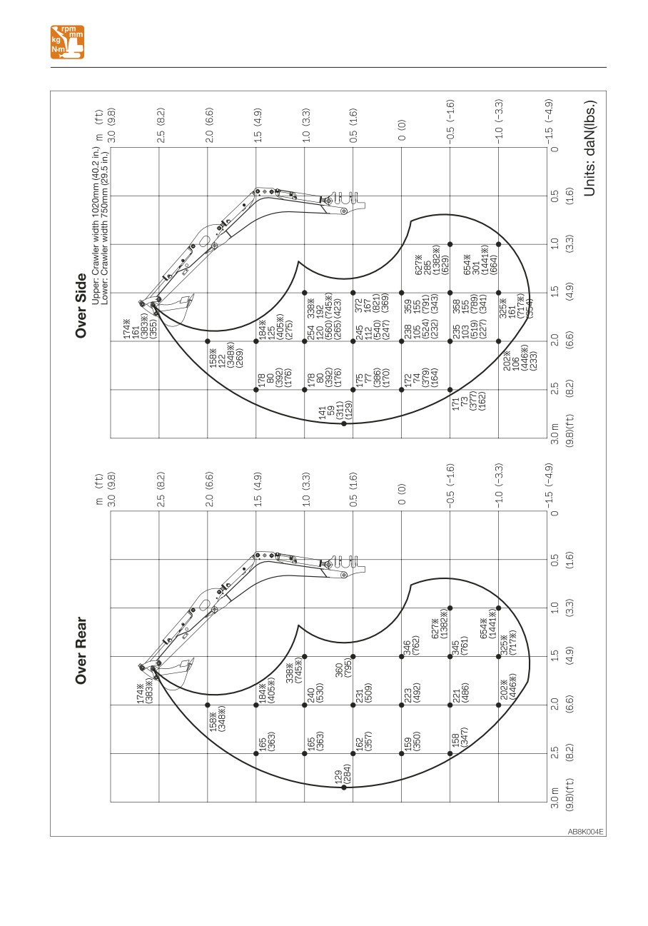
LIFTING CAPACITIES
Rated lift capacity chart
• Do not attempt to lift or hold any load
• The loads in the charts do not exceed 87%
that is greater than these rated values at
of hydraulic lift capacity or 75% of tipping
their specified load radii and height.
load.
• The rated lift capacities are based on
• Figures marked with an asterisk (
) are
the machine being level and situated on
hydraulically-limited capacities.
a firm supporting surface. For safe
• The mass of slings and any other lifting
lifting, the operator is expected to make
devices shall be deducted from the rated
due allowance for the particular job
load to determine the net load that may be
conditions such as soft or uneven
lifted.
ground, non-level condition, side loads,
• The load point is the bucket hinge pin, and
hazardous conditions, experience of
the bucket posture is with the standard
personnel, etc. The operator and other
bucket completely retracted under the arm.
personnel should fully acquaint
• Unit: daN (lbs)
themselves with the operator’s manual
furnished by the manufacturer before
Load hooking system
operating this machine. When operating
A load hooking system must be provided
the machine, the safety rules of the
with the following capabilities.
equipment must also be followed.
1. A system which can withstand two-and-a-
• Do not travel while lifting a load; It is
half times the rated lift capacity no matter
very dangerous.
at what position the load is applied.
2. A system that poses no risk of the lifted
load falling from the hooking device. For
example, equipped with a hook slippage
prevention device.
3. A system that poses no risk of the hooking
system slipping from the hoe attachment.
7-11
SPECIFICATIONS
LIFTING CAPACITIES
7-12
SPECIFICATIONS
LIFTING CAPACITIES
7-13
7-14
OPTIONS
8-1
OPTIONS
GENERAL PRECAUTIONS
• Use the proper procedure when
GENERAL PRECAUTIONS
mounting a boom or arm; otherwise
SAFETY PRECAUTIONS
serious damage could result. Consult
your sales or service dealer for help.
When removing or installing an
attachment or optional part, take the
CAUTIONS WHEN INSTALLING
following precautions.
ATTACHMENTS
• Consult with Takeuchi before installing
an optional attachment.
Be sure to perform a test operation after an
• Do not use any attachments not
optional or other special attachment has
approved by Takeuchi. Doing so may
been replaced. Inspect the hydraulic oil level
cause safety problems. Or, it may
and recharge it as necessary. Consult your
adversely affect the machine’s operation
sales or service dealer for detailed
or service life.
procedures on installing/removing
• We will not be held responsible for any
attachments.
injuries, accidents or damage to its
products caused by the use by a non-
approved attachment.
• Select a firm, level work area. Also, be
sure to park in a well ventilated place.
• Clear obstacles and dangerous objects,
and clean up spilled fuel immediately.
• When hoisting, be sure to designate a
person to act as a signalman.
Follow the instructions of the signalman
regarding the procedure and measures.
• When it is necessary to temporally
place a heavy object or an attachment
on the ground during removal or
installation, be sure to place it in a
stable position.
• Keep everyone out of the area when
hoisting. There is a hazard of objects
falling or contacting with people in the
area.
• Use a crane to move heavy objects (25
kg (55 lb.) or greater).
• Before removing a heavy object, be sure
to put a support to it. When lifting with a
crane, pay attention to the center of
gravity of the load to keep the machine
in balance.
• Do not operate the machine while the
load is lifted by a crane stand.
8-2
OPTIONS
GENERAL PRECAUTIONS
CAUTIONS WHEN OPERATING
• Slewing on slopes
ATTACHMENTS
• If there is a heavy attachment is
installed, the machine takes longer
distance than usual to come to a
complete stop when the stopping
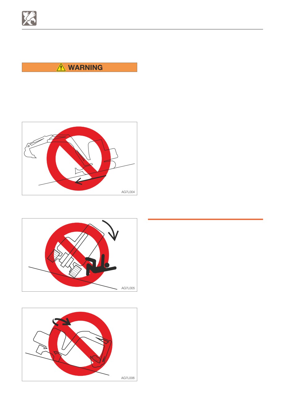
Long attachments reduce stability of the
operation is performed. Carefully judge
machine. The machine may tip over if it
the distance so as not to bump into an
loses the balance when traveling or
object around the machine. Keep a safe
slewing on slopes.
distance from surrounding obstacles.
Never perform the operations listed below
When a heavy attachment is installed,
as they are extremely dangerous.
natural drop (the gradual dropping of
the attachment under its own weight
when it is stopped in midair) increases.
• The machine can tip over more easily in
the lateral direction than in the
longitudinal direction.
· Do not slew sideways with a heavy
load at the how attachment. In
particular, do not slew sideways on
slopes.
· The attachment is heavier for
machines equipped with breakers or
crushers than for machines equipped
• Traveling down the slopes with the
with the standard bucket. Do not
attachment raised
operate such machines sideways,
especially digging downhill.
• Traveling across slopes
8-3
OPTIONS
ATTACHMENT COMBINATION TABLE
ATTACHMENT COMBINATION TABLE
The table below shows the bucket to be installed on the arm. Select a proper bucket by
following the table.
• Consult with Takeuchi before installing an optional attachment.
• Do not use any attachments not approved by Takeuchi. Doing so may cause safety
problems. Or, it may adversely affect the machine’s operation or service life.
• We will not be held responsible for any injuries, accidents or damage to its products
caused by the use by a non-approved attachment.
√ :Can be used.
∆ :Can be used only for light operations (digging and loading of dry and loose soil or mud)
—:Cannot be used.
Rated capacity
Bucket cutting width
Standard arm
Bucket
m3 (cu. ft.)
mm (inch)
880 mm (34.6 in.)
350W
0.022
(0.76)
350 (13.8)
√
8-4
OPTIONS
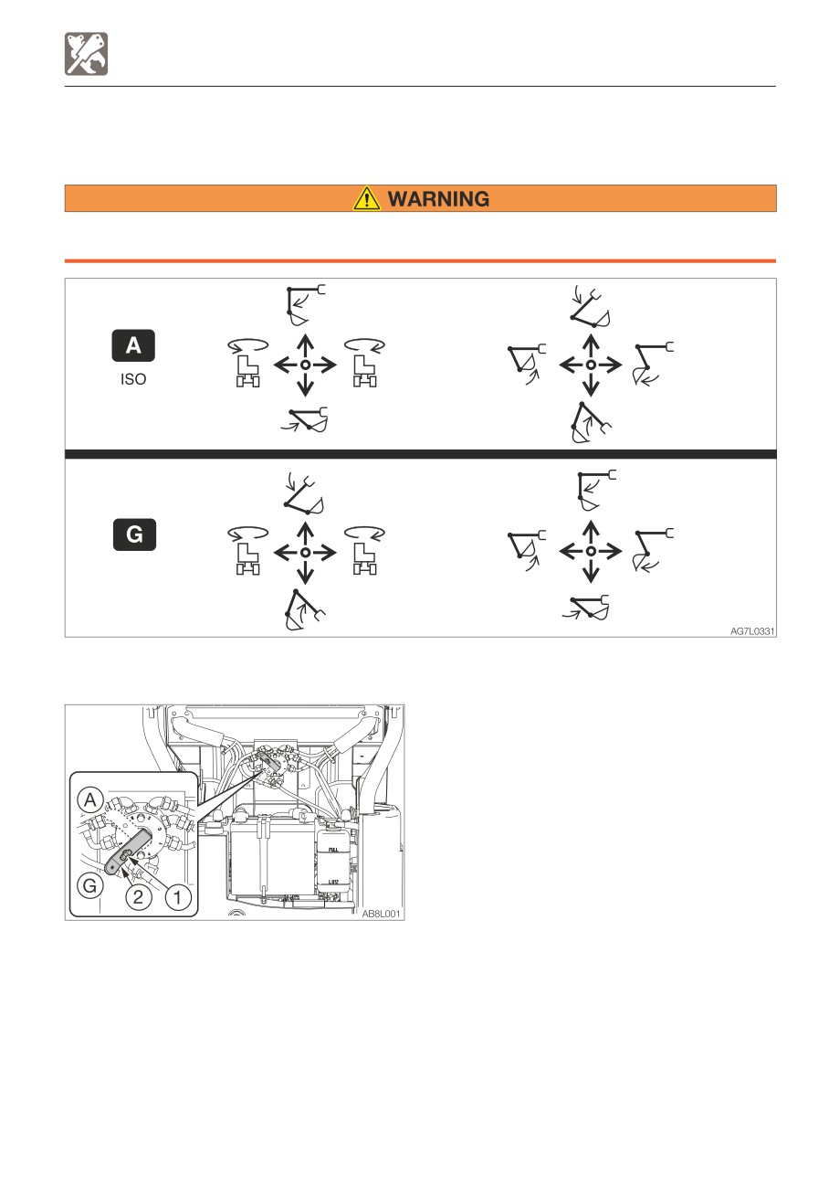
SELECTING A LEVER PATTERN
SELECTING A LEVER PATTERN
The operating pattern of the left and right operating levers can be changed.
Before starting the engine, check the selector to see which operating pattern the left
and right operating levers are set.
SWITCHING THE LEVER PATTERN
1. Park the machine on a flat and rigid
ground, and stop the engine.
2. Open the engine hood.
3. Loosen the wing bolt (1).
4. Turn the selector valve lever (2) to switch
the pattern.
5. Tighten the wing bolt (1) and fasten the
lever (2) in place.
6. Close the engine hood.
7. Confirm the lever pattern.
(A) : ISO pattern
(G) : G pattern
8-5
OPTIONS
HYDRAULIC BREAKER
Cautions on operating
HYDRAULIC BREAKER
For handling of the breaker, read the
hydraulic breaker’s manual, provided
separately.
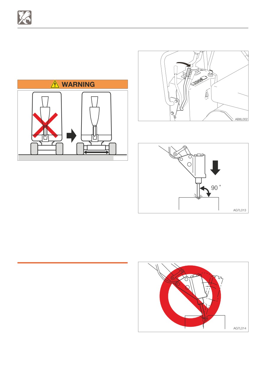
• Start the engine and run it at 75% of the
maximum speed.
AD6A001
Do not use the breaker when the crawler
width is narrowed!
• Always operate the machine with the
crawler width extended to 1020 mm
(40.2 in.) to maximize the machine
stability. If the machine is operated with
the crawler width narrowed (750 mm,
29.5 in.), the machine may tip over due
to its poor stability.
• Pound with the chisel pressed
• If the machine must be operated with
perpendicular to the surface to be
the narrowed crawler width (750 mm,
pounded.
29.5 in.), traveling should be done after
• When pounding, press the chisel properly
folding the hoe attachment, lowering the
against the object to be broken so as to
boom to lower the center of gravity and
avoid pounding the air.
keeping the machine facing forward.
When an optional attachment, such as a
breaker, tilted bucket or clamshell, is
operated, be sure that the crawler width is
extended to 1020 mm (40.2 in.).
IMPORTANT: When installing an
attachment, make sure that it is
appropriate for the machine being used.
Contact your sales or service dealer for
advice on selecting attachments.
• Do not pry with the chisel or do not pry
while pounding.
• Do not move the chisel while pounding.
• Do not pound continuously for over 30
seconds on the same surface.
8-6
OPTIONS
HYDRAULIC BREAKER
REPLACING THE HYDRAULIC OIL
REGULARLY
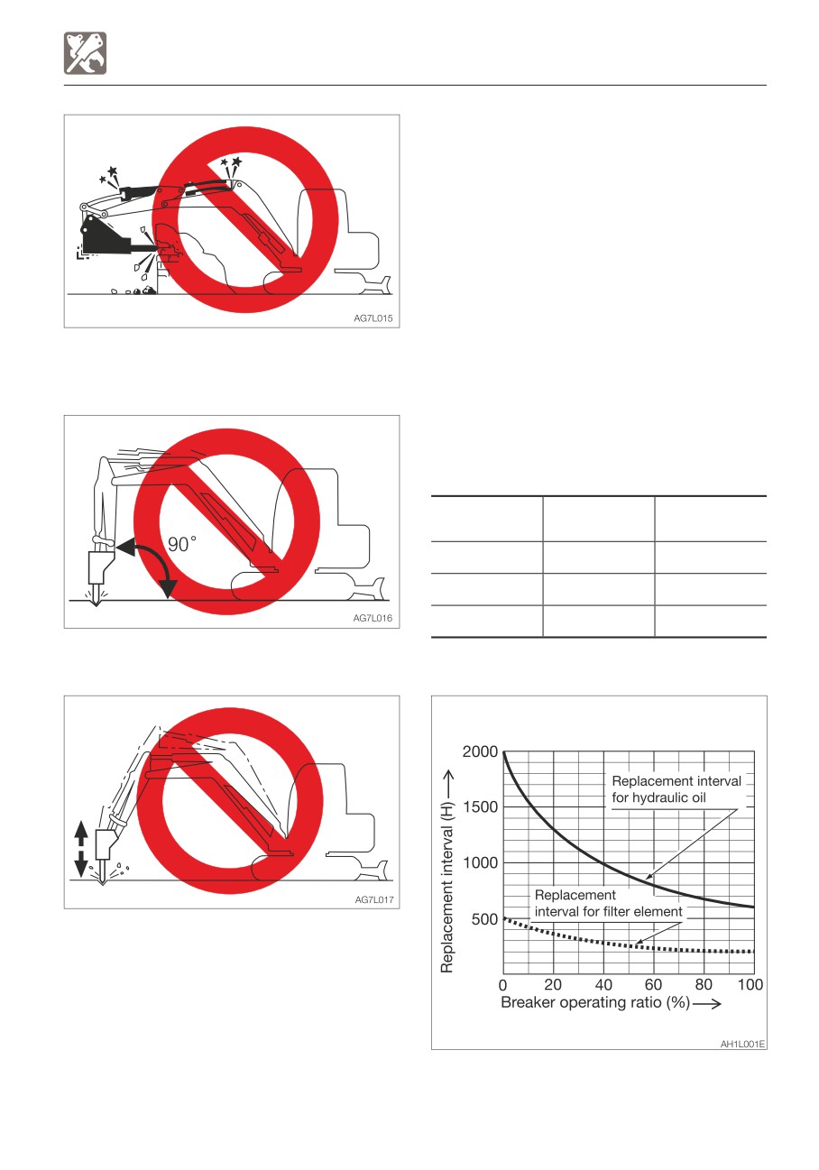
When a hydraulic breaker is used, the oil
deteriorates more quickly than that used for
a usual operation. Be sure to replace the
hydraulic oil and the return filter elements.
• Failure to replace these in time can lead to
damage to the machine and the breaker
hydraulic system. To improve the service
life of the hydraulic systems, be sure to
• Do not pound with the cylinder fully
replace the hydraulic oil and return filter
extended or retracted (at the stroke end).
element after the number of hours shown
Leave a margin of at least 50mm(2 in).
on the diagram below.
• When replacing the hydraulic oil, clean the
suction strainer.
Replacement interval (hours)
Filter
Item
Hydraulic oil
element
1st time
—
25
2nd time
—
100
Periodically
600
200
• Do not pound with the arm placed
perpendicular to the ground surface.
When the breaker operating ratio is 100%.
• Do not drop the breaker itself on the object
to be broken in order to break it.
• Do not move objects to be broken or rocks
with the breaker itself.
• Slew the machine occasionally to cool the
engine.
• If a hydraulic hose is vibrating abnormally,
nitrogen gas may be leaking from the
accumulator. Ask for an inspection early.
8-7
OPTIONS
BIODEGRADABLE OIL
4. Bleed the air from the hydraulic oil system.
BIODEGRADABLE OIL
5. Operate the hydraulic devices for 30
Biodegradable oil is a new type of hydraulic
minutes.
oil that is decomposed into carbon dioxide
6. Drain the biodegradable oil from the tank
and water by microorganisms in the soil and
and cylinders.
water. It is highly safe for living organisms
7. Replace the hydraulic oil return filter with a
and offers advantages in term of
new filter.
environmental protection.
8. Repeat steps 3 and 4.
• Recommended biodegradable oil: Mobile
9. Operate the hydraulic devices for 30
EAL Envirosyn 46H (an ester synthetic oil).
minutes.
When replacing the hydraulic oil with
10. Drain the biodegradable oil from the tank
biodegradable oil, use the above or an
and cylinders.
equivalent oil.
11. Repeat steps 3 and 4.
Note that other oils, even other brands of
12. Operate the hydraulic devices for 1 hour.
ester synthetic oils, may damage O-rings,
13. Drain the biodegradable oil from the tank
packings and seals. Takeuchi products
and cylinders.
shipped with the optional biodegradable oil
14. Replace the return filter with a new filter.
are shipped with the above brand of oil.
15. Repeat steps 3 and 4.
• When switching from a mineral oil to a
16. Operate the hydraulic devices, then
biodegradable oil, the parking brake torque
check for oil leakage.
decreases by about 30%.
There is no need to flush the hydraulic oil
system when switching from biodegradable
to mineral hydraulic oil.
REPLACING THE HYDRAULIC OIL WITH
BIODEGRADABLE OIL
Mixing mineral oil with biodegradable oil will
result in a decrease of the hydraulic oil’s
performance as well as a decrease in
biodegradability and safety. The hydraulic oil
system must be flushed as described below
before supplying the biodegradable oil. This
operation is dangerous and requires
experience. Have it performed by a Takeuchi
sales or service outlet.
Flushing
To be performed by a Takeuchi sales or
service outlet
1. Drain the hydraulic oil (mineral oil) from the
hydraulic oil tank and clean the inside of
the tank and suction strainer.
Refer to “Replacing the hydraulic oil and
cleaning the suction strainer” on page
5-43.
2. Remove the cylinder hoses and drain the
hydraulic oil (mineral oil) from inside the
cylinders.
3. Supply new biodegradable oil to the
hydraulic oil tank.
8-8
OPTIONS
TRAVEL ALARM
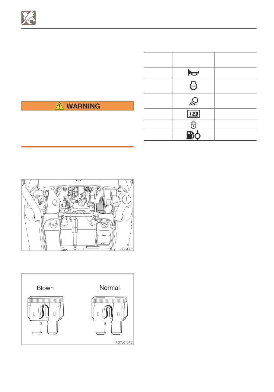
Fuse layout and circuits protected
TRAVEL ALARM
The alarm sounds while the machine is
Protected
traveling and stops when the machine stops
Capacity
Symbol
circuit
traveling.
10A
Horn
If the alarm does not sound when the
machine travels, the fuse may be blown.
Engine stop
30A
Inspect the fuses.
solenoid
Boom light,
20A
Travel alarm
If the fuse blows again soon after
10A
Hour meter
replacement, then the electric system is
15A
Lever lock
likely faulty. It may pose a fire hazard if
not properly repaired. Contact your sales
3A
Feed pump
or service dealer for advice.
1. Turn the starter key to the OFF position to
stop the engine.
2. Open the engine hood.
3. Open the fuse box cover (1).
4. Check for fuse.
5. If a fuse is blown, replace it with a spare
fuse of the same capacity.
8-9
OPTIONS
TAKEUCHI SECURITY SYSTEM
STARTING THE ENGINE
TAKEUCHI SECURITY SYSTEM
The Takeuchi Security System is a system
that allows only registered starter keys to be
used for starting the engine.
The engine cannot be started with any
unregistered or counterfeit starter keys. If a
registered starter key is lost or stolen, you
can set the system to delete the registered
key information, so that the lost or stolen key
cannot be used to start the engine. Although
machine theft cannot be completely
prevented, the system certainly helps reduce
the risk of theft.
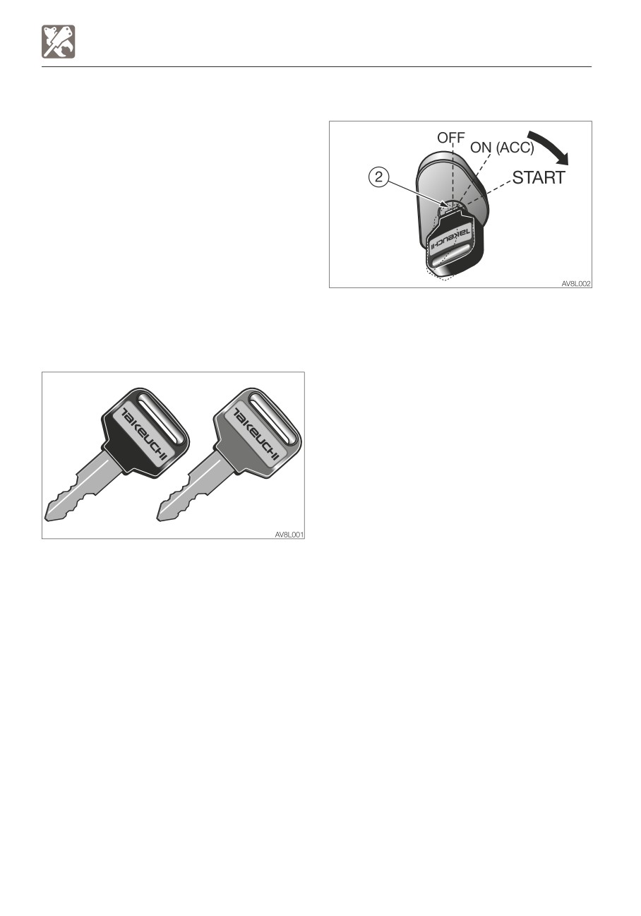
The engine can be started using the normal
method with a registered BLACK key.
The engine cannot be started using the RED
STARTER KEY
master key.
Refer to Chapter 3, “Starting and stopping
the engine”.
There are two types of starter key, red and
black, which can be registered in the
Takeuchi Security System.
The red key is the master key. The black key
is the starting key.
8-10
OPTIONS
TAKEUCHI SECURITY SYSTEM
If an attempt is made to start the engine
REGISTERING AND DELETING THE
with an unregistered key:
STARTER KEY
If an unregistered starter key is turned from
To register or delete the starter key, use a
the OFF to the ON (ACC) position, the alarm
tool specifically designed for this purpose.
starts sounding.
Consult your sales or service dealer for help.
If this attempt is repeated five times in a row,
the horn sounds for two minutes, and the
engine cannot be started. The horn stops
when the key is turned to the OFF position.
8-11
OPTIONS
TAKEUCHI SECURITY SYSTEM
IF THE MASTER KEY IS LOST
If you lose your master key, contact your
service or sales dealer for assistance.
COUNTRIES WHERE THE SYSTEM CAN
BE USED
To use the Takeuchi Security System, “radio
wave authentication” must be obtained in the
country where the system is to be used.
The system can be used in the countries
listed below, as of January 2017. Do not use
the system in other countries. For details on
how to disable the system, please contact
your service or sales dealer for assistance.
Countries where the system can be used:
Ireland, Italy, UK, Estonia, Austria, Holland,
Cyprus, Greece, Croatia, Sweden, Spain,
Slovakia, Slovenia, Czech, Denmark,
Germany, Hungary, Finland, France,
Bulgaria, Belgium, Poland, Portugal, Malta,
Latvia, Lithuania, Rumania, Luxemburg,
Iceland, Norway, Liechtenstein,
Switzerland, Turkey
8-12
OPTIONS
ADJUSTABLE LEVER STANDS
ADJUSTABLE LEVER STANDS
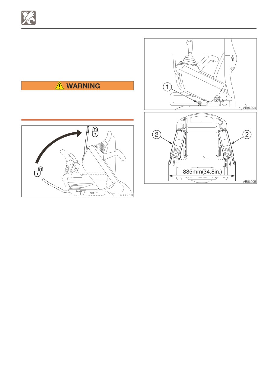
By spreading the lever stands to the left and
right, you can have more space for your
knees and thighs.
Move the lever stands to where you want
to secure them. Operating the machine
without securing the lever stands could
result in an accident.
2. Move the lever stands (2) while pressing
the button (1). (Two-point adjustment is
1. Set the safety lock lever to the locked
available.)
position.
Note: When the lever stands are spread, the
maximum width between the front ends of
the stands is 885 mm (34.8 in), which is
larger than the crawler overall width (narrow).
8-13
Declaration of Conformity
We herewith declare that following named machine, based on its conception and design
and in the form brought into service is in accordance with the relevant, basic safety and
health requirements of the following EU directives. In case of any alteration of the
machine not coordinated with us, this certificate loses its validity.
Designation of the machine Compact Excavator
Manufacturer
TAKEUCHI MFG. CO., LTD
205 Uwadaira, Sakaki-machi, Hanishina-gun, Nagano
389-0605, Japan
Model
TB210R
Engine type
D722-EF13 (e1*2016/1628*2016/1628EV2/D*0008*∆)
Engine power
8.8 kW @ 2200 rpm
The machine is in accordance with the requirements of EU directives:
1) Machine directive 2006/42/EC and appendix
2) Electromagnetic compatibility-regulation 2014/30/EU and appendix
3) Noise directive 2000/14/EC (Evaluation procedure according to appendix VI),
2005/88/EC and appendices.
4) Regulations on engine emissions: Regulation (EU) 2016/1628, as last amended by
Regulation 2016/1628.
Harmonized norms: EN474-1:2006+A4:2013, EN474-5:2006+A3:2013.
Compiler of the technical files:
Oliver Scharschmidt
Wilhelm Schäfer GmbH
68307 Mannheim-Sandhofen GERMANY
Issued in Sakaki, Japan
Akio Takeuchi, Chairman