Takeuchi compact excavator TB210R (Serial No. 211000004~). Operators Manual (2019) - page 2
SAFETY
SAFETY SIGNS (DECALS)
SAFETY SIGNS (DECALS)
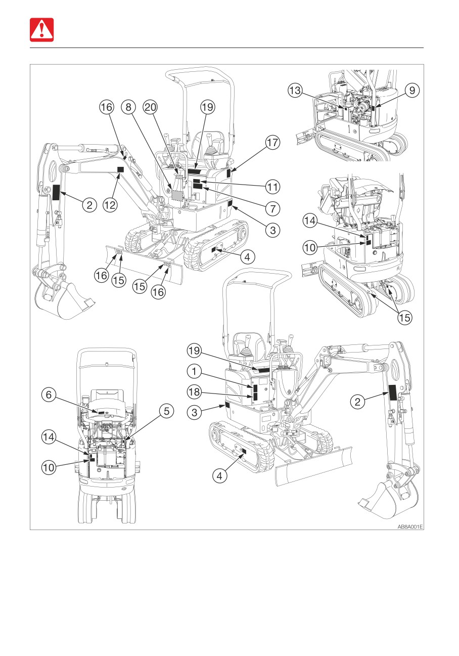
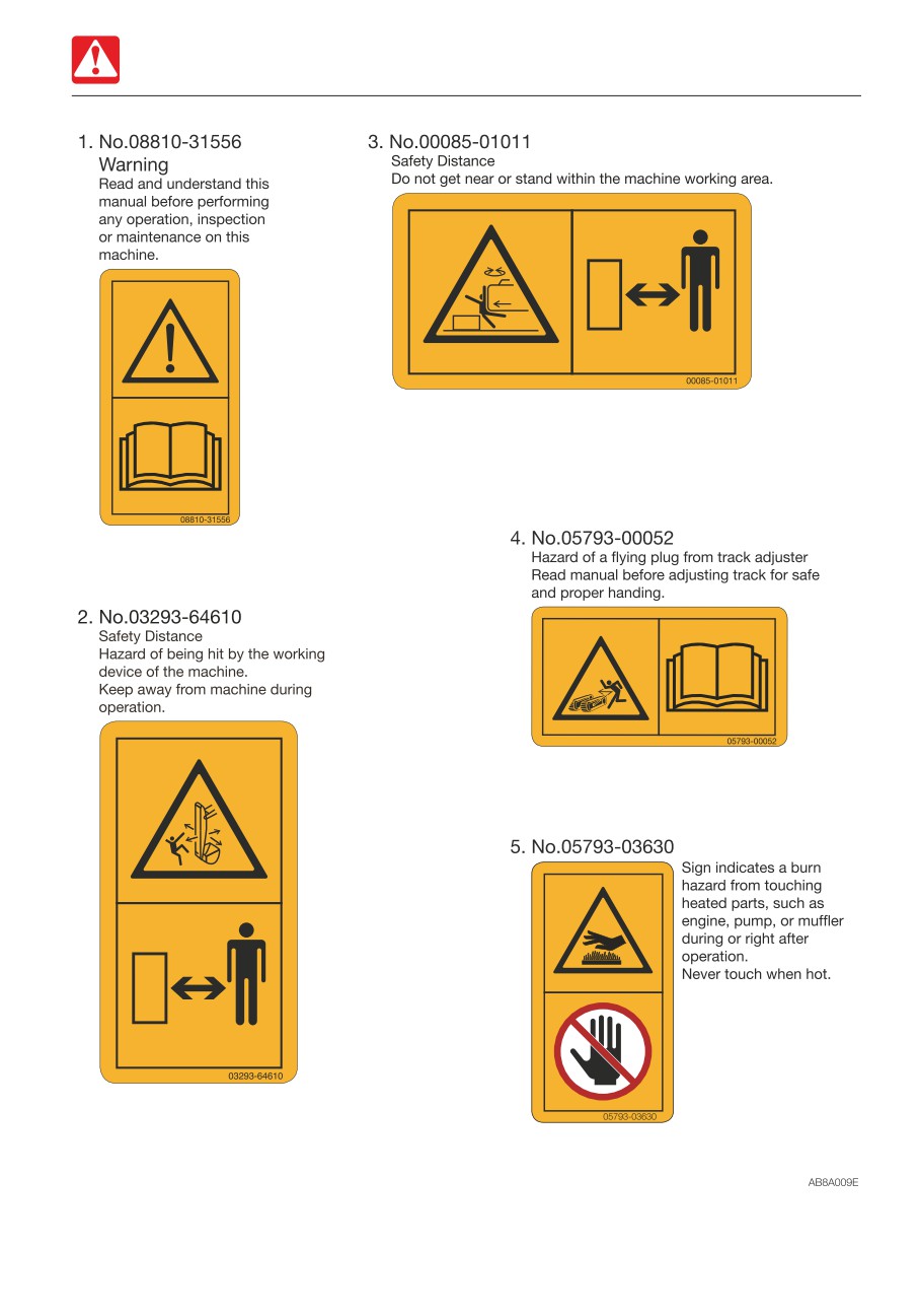
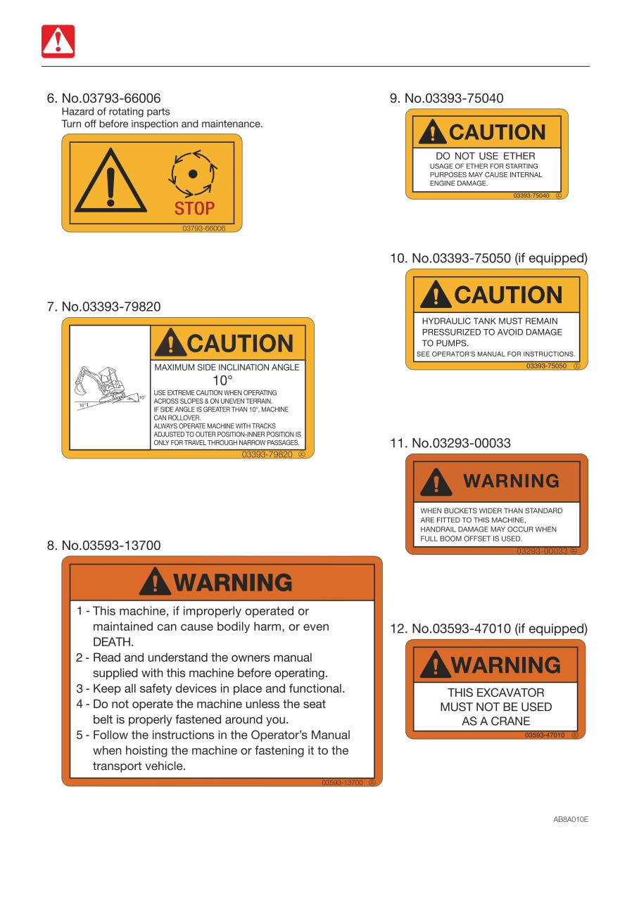
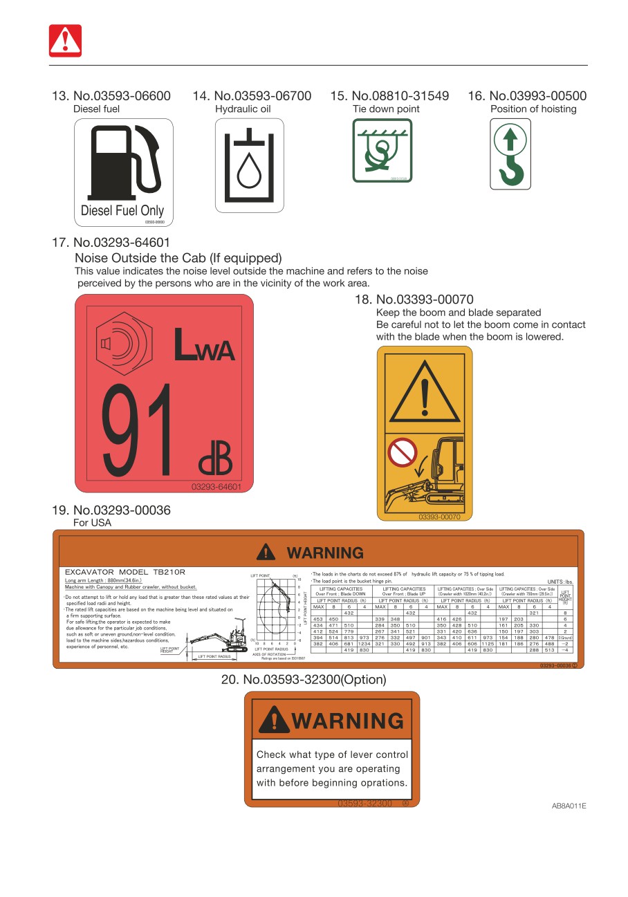
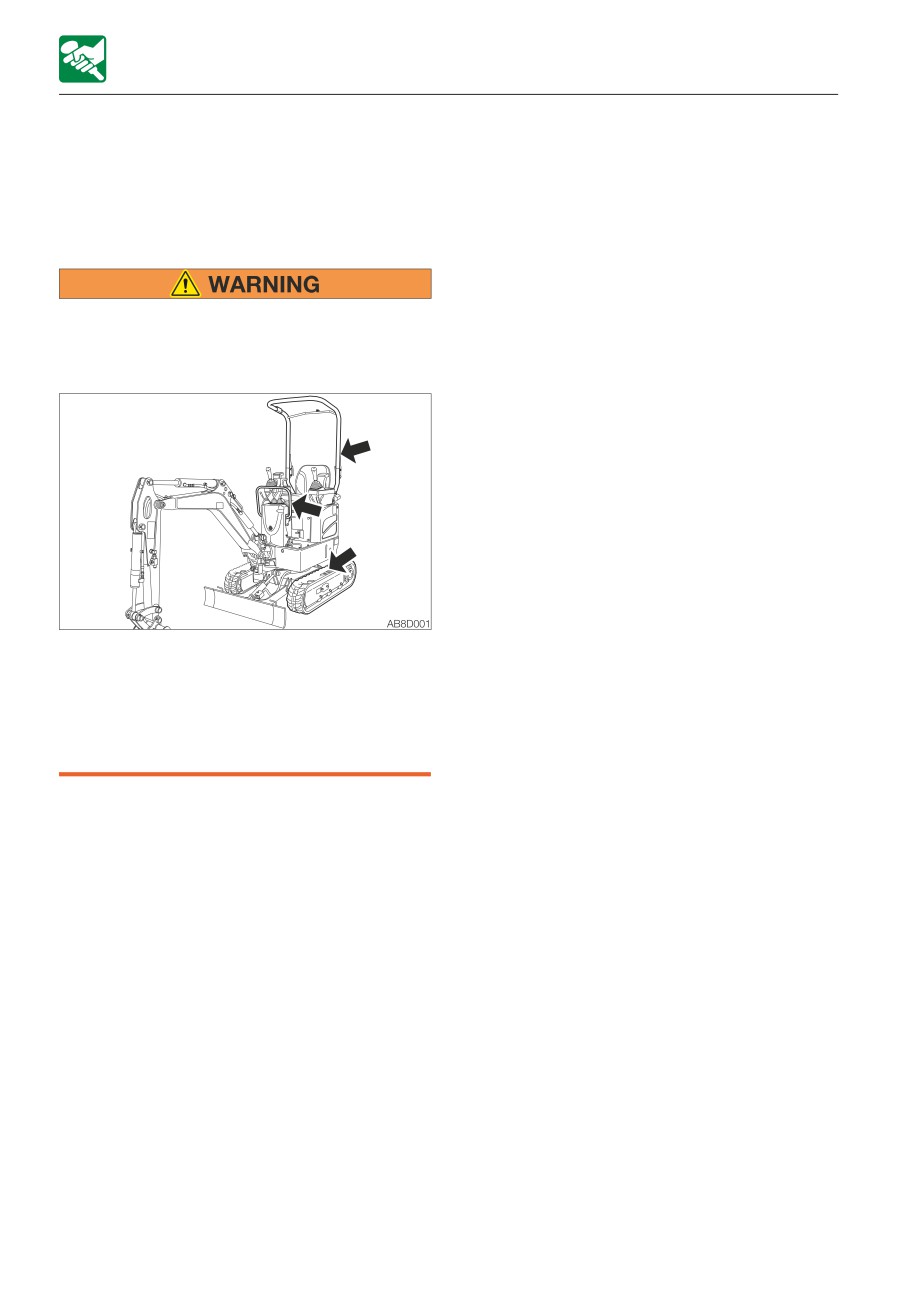
For the safety of the operator and the personnel working around the site, safety signs (decals)
are placed at certain locations on the machine as shown below. Walk around the machine with
this manual, and check the content and location of these safety signs. Review these signs and
the operating instructions in this manual with your machine operators.
• Keep the signs clean and legible. If any of the safety labels is peeling or damaged and
becomes difficult to read, replace it with a new one. Please include your product serial
number when ordering a new sign from the Takeuchi service agent.
• When a part/unit to which a safety sign is attached is replenished, a new sign must be
attached to the new part/unit.
1-33
SAFETY
SAFETY SIGNS (DECALS)
1-34
SAFETY
SAFETY SIGNS (DECALS)
1-35
SAFETY
SAFETY SIGNS (DECALS)
1-36
SAFETY
SAFETY SIGNS (DECALS)
1-37
1-38
CONTROLS
2-1
CONTROLS
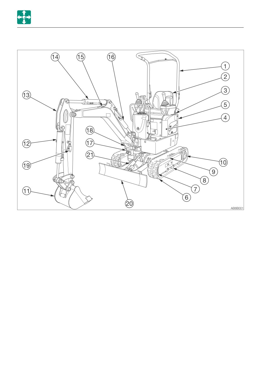
NAMES OF COMPONENTS
NAMES OF COMPONENTS
Upperstructure
Undercarriage
Working equipment
1. Canopy
6. Crawler belt
11. Bucket
2. Seat
7. Idler
12. Bucket cylinder
3. Engine hood
8. Track roller
13. Arm
4. Fuel tank
9. Shoe slide
14. Arm cylinder
5. Hydraulic oil tank
10. Travel motor
15. Boom
16. Boom cylinder
17. Boom bracket
18. Swing cylinder
19. Auxiliary hydraulic lines
20. Dozer blade
21. Blade cylinder
2-2
CONTROLS
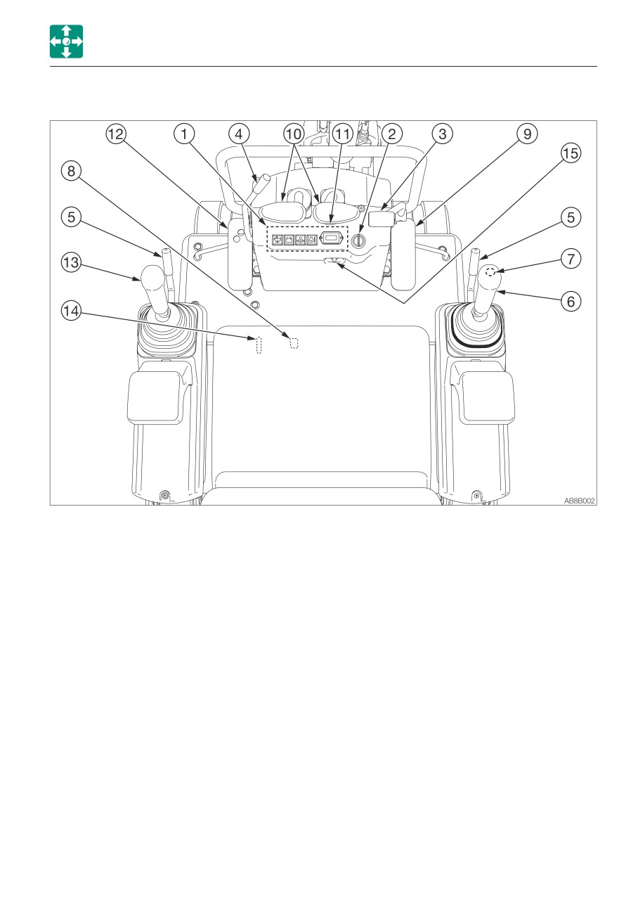
NAMES OF COMPONENTS
1. Instruments
10. Travel levers
2. Starter switch
11. Travel speed switch
3. Blade lever
12. Auxiliary hydraulic pedal
4. Throttle lever
13. Left operating lever
5. Safety lock levers
14. Slew lock lever
6. Right operating lever
15. Power supply socket
7. Horn button
8. Selector lever
9. Boom swing pedal
*: Subject to the specifications or optional products selected
2-3
CONTROLS
COVERS
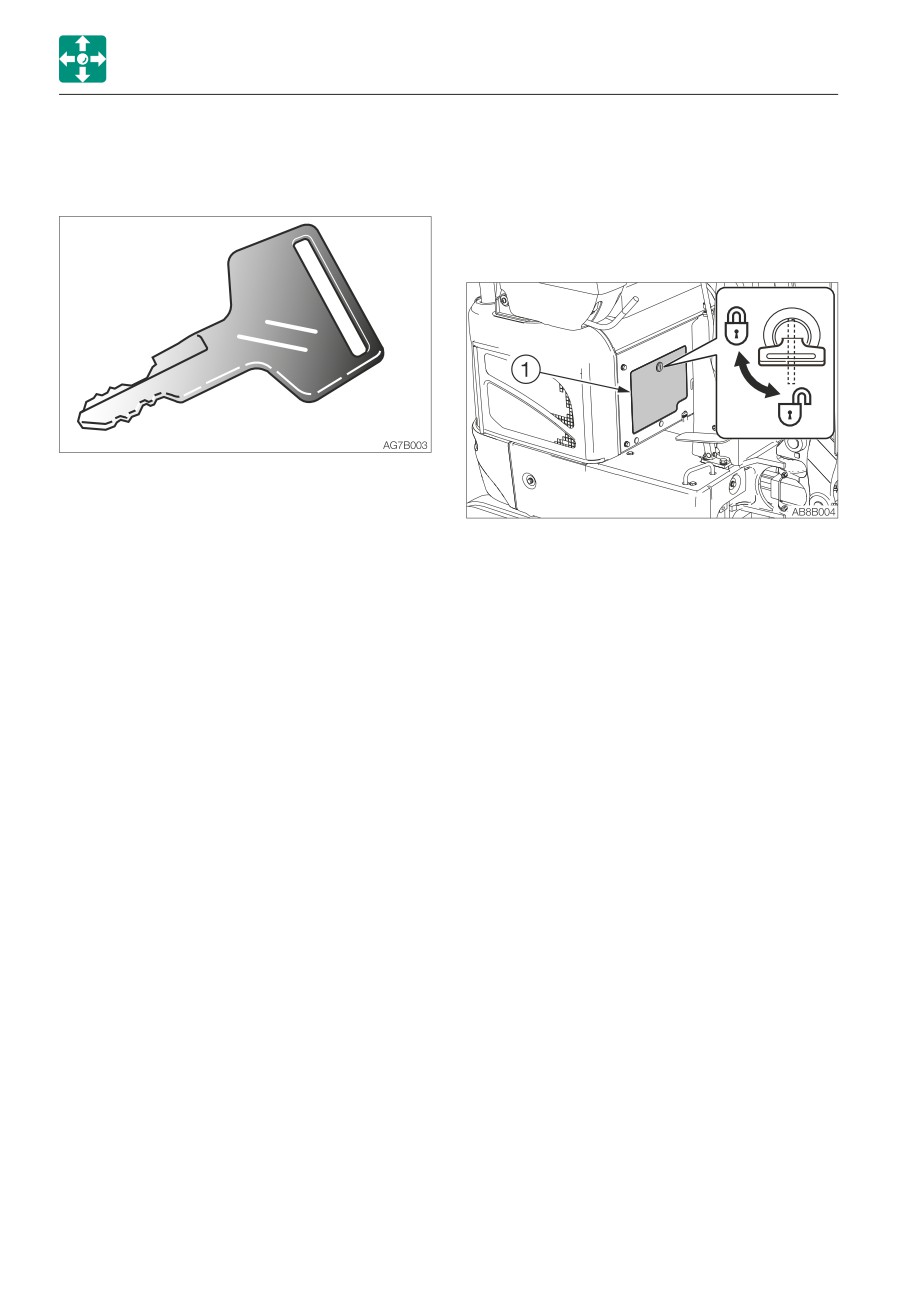
MAINTENANCE COVER
COVERS
STARTER KEY
Open this cover to perform a maintenance
operation of the engine.
Opening
The starter key is used to start and stop the
engine, as well as to lock and unlock the
following components:
• Fuel lid
1. Insert the starter key and turn it
• Engine hood
counterclockwise to unlock the
• Maintenance cover
maintenance cover (1).
Closing
1. Close the maintenance cover (1).
2. Insert the starter key and turn it clockwise
to lock the maintenance cover (1).
2-4
CONTROLS
COVERS
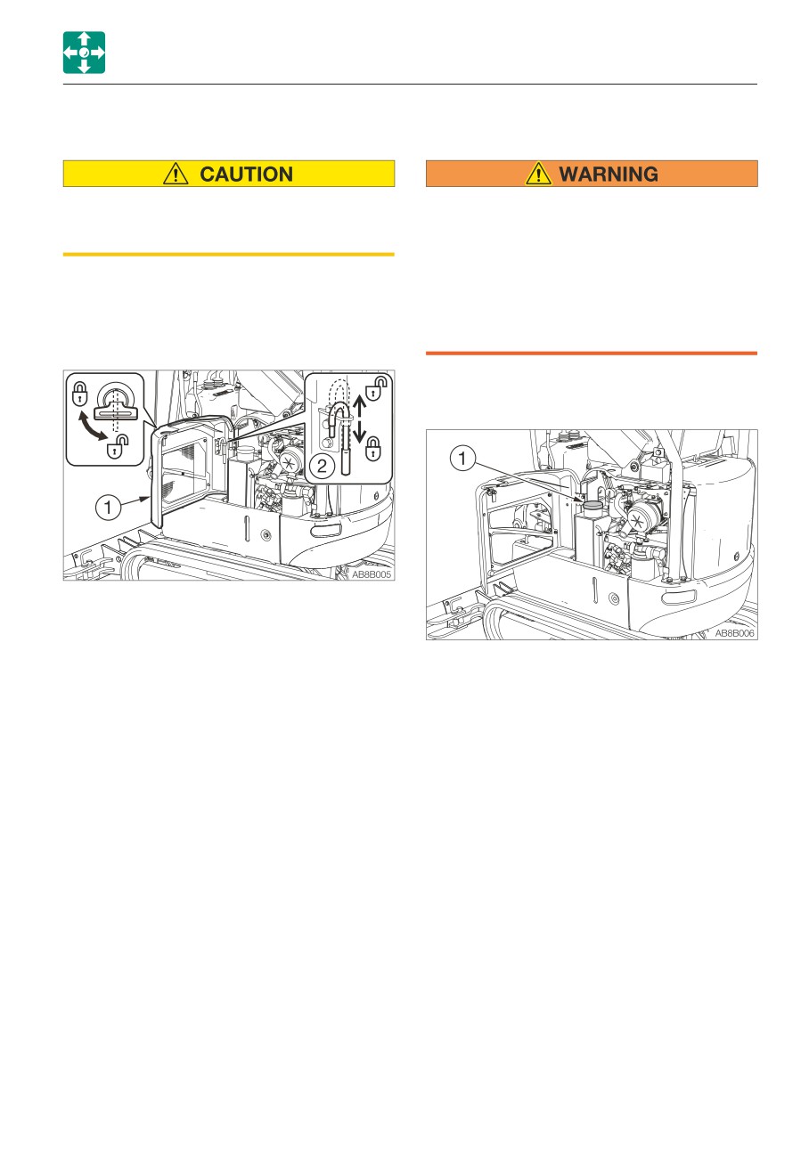
FUEL LID
FUEL FILLER PORT
When opening and closing the fuel lid, be
• Do not smoke and keep away from heat
careful not to get your hands caught by
or flame while filling the fuel tank.
the lid.
• Fill the fuel tank in a well ventilated
place, with the engine turned off.
For adding fuel or performing maintenance,
• Clean up spilled fuel immediately.
open this cover.
• Do not fill the fuel tank to capacity.
Allow room for oil expansion.
Opening
• Securely tighten the fuel filler cap.
Opening
1. Insert the starter key and turn it
counterclockwise to unlock the fuel lid (1).
2. Open the fuel lid (1) all the way to the end.
(It is locked automatically.)
1. Open the fuel lid.
2. Turn the fuel cap (1) counterclockwise and
Closing
remove it.
1. Support the fuel lid (1) by hand and lift the
stay (2) to release the lid.
Closing
2. Close the fuel lid (1).
1. Turn the fuel cap (1) it clockwise and close
3. Insert the starter key and turn it clockwise
it.
to lock the fuel lid (1).
2. Close the fuel lid and lock it.
2-5
CONTROLS
COVERS
ENGINE HOOD
Opening
• Before opening the engine hood, be
sure to stop the engine. If a hand or tool
becomes trapped in the rotating or
moving part, serious injury could result.
• Opening or closing the engine hood
while the engine is running may cause
the machine to move, resulting in
serious injury or death. Be sure to stop
the engine before opening or closing the
engine hood.
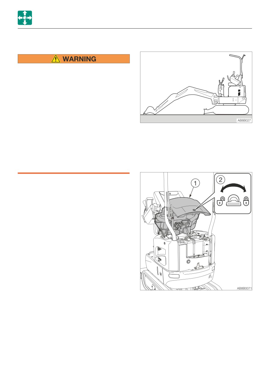
1. Select a firm and level surface, set the
• Do not leave the engine hood open on a
working equipment to the posture shown
windy day or if the machine is parked
in the diagram above, lower it to the
on a slope.
ground, and then stop the engine.
• When opening or closing the engine
2. Raise the safety lock lever to the locked
hood, be careful not to get your hands
position.
or other parts of your body caught by it.
IMPORTANT: Before opening or closing
the engine hood, check if the boom is
offset to either side. If it is, set it in the
neutral position to avoid interference
between the main body and the hoe
attachment, and then fully extend the how
attachment to the ground.
If the engine hood is opened while the
hoe attachment is raised and the boom is
in its full swing position, the hoe
attachment could come into contact with
the main body.
Open the engine food to perform a
maintenance operation or to switch the
selector valve.
3. Insert the starter key and turn it
counterclockwise to unlock the engine
hood (1).
4. Push in the key hole (2) with your thumb
and open the engine hood (1).
5. Open the engine hood (1) all the way until
it stops.
Closing
1. Close the engine hood (1).
2. Insert the starter key and turn it clockwise
to lock the engine hood (1).
2-6
CONTROLS
FOLDING DOWN THE CANOPY
FOLDING DOWN THE CANOPY
Do not operate the machine with the
canopy folded down.
The TOPS will not be applicable to the
machine if the canopy is folded down.
TOPS (ISO12117): Tip-over protection
structure
When folding down the upper canopy, be
sure to lower it slowly. If lowered too
rapidly, the canopy could come in contact
with your body, resulting in an injury.
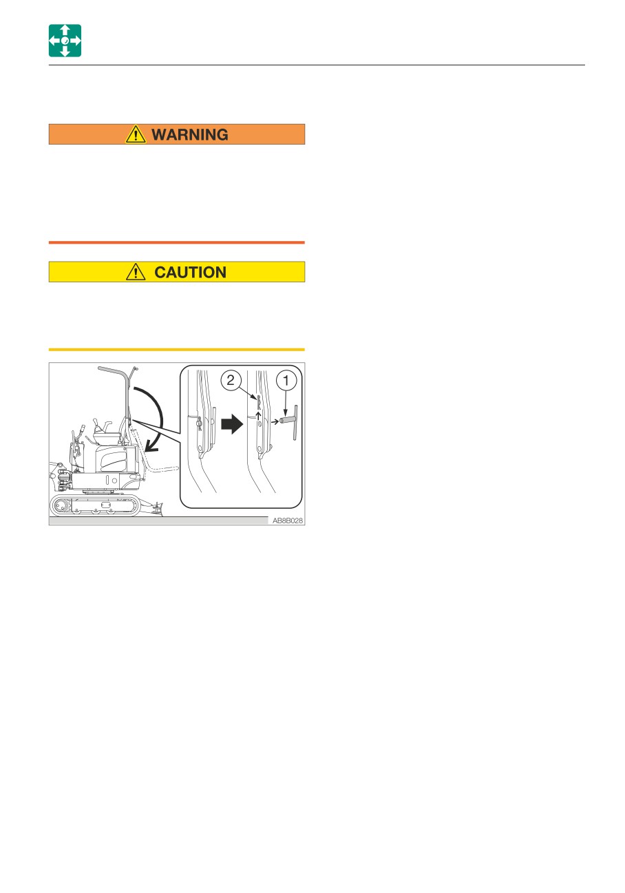
1. Pull out the R-pins (2) from the lock pins
(1) on the left and right sides.
2. Pull out the lock pin (1) from one side.
3. Pull out the other side lock pin (1) while
supporting the upper canopy (15 kg/35 lb)
by hand.
4. Slowly lower the upper canopy in a
rearward direction to fold it down.
2-7
CONTROLS
SEAT AND SEAT BELT
SEAT AND SEAT BELT
SEAT
Adjust and secure the seat.
Fore-and-aft adjustment
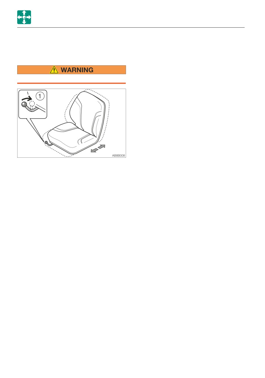
1. Pull up the lever (1) and slide the seat
backward or forward to the desired
position for operation of machine.
2. Release the lever (1) at the desired
position to secure the seat.
Adjustment range: 15 positions, in 200
mm (7.9 in.)
2-8
CONTROLS
SEAT AND SEAT BELT
SEAT BELT
Releasing the seat belt
Be sure to fasten the seat belt securely
C
before starting the engine.
B
Fastening the seat belt
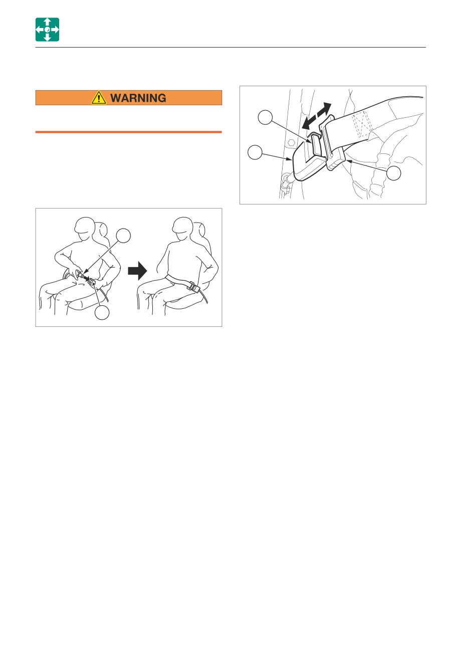
1. Adjust the seat to the desired position for
A
operation, sit up and sit back in the chair.
2. Pull the seat belt to the desired length.
AG7B024
1. Grasp the tongue plate (A) and press the
button (C) on the buckle (B).
A
The seat belt retracts back into its original
position.
B
AG7B023
3. Make sure that the belt is not twisted and
then insert the tongue plate (A) into the
buckle (B) of the seat belt until you hear a
clicking sound as it locks in place.
4. Check if the belt is securely locked by
pulling it, and arrange the belt around your
waist.
2-9
CONTROLS
INSTRUMENTS
INSTRUMENTS
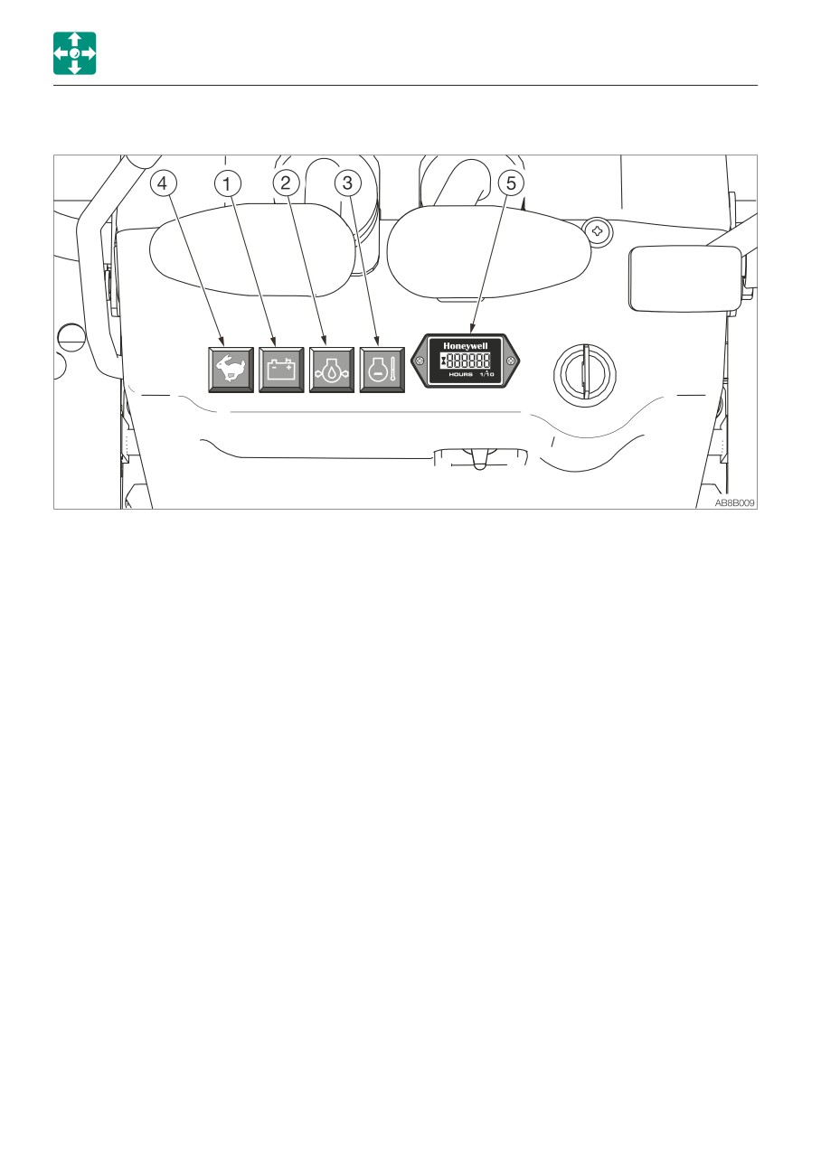
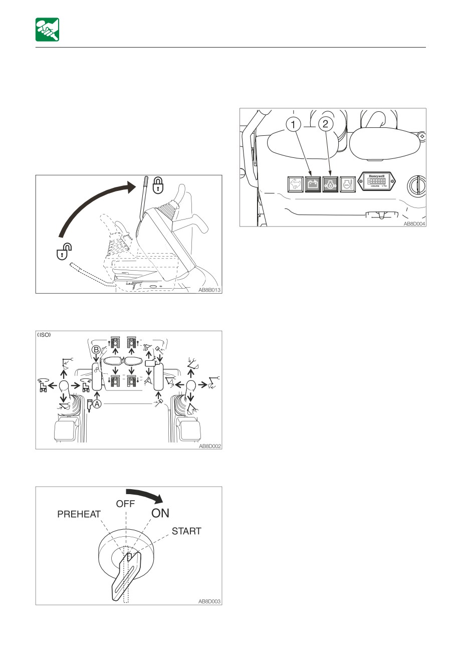
Once the starter switch is turned to ON, the battery charge warning lamp (1) and the engine oil
pressure warning lamp (2) light up. The machine system is normal if the lamps turn off after the
engine is started.
If either lamp does not light up, there is something wrong in the machine. Consult your sales or
service dealer.
WARNING LAMPS
2. Engine oil pressure warning lamp
This lamp lights up if the lubricant pressure
IMPORTANT: If a warning lamp lights up,
becomes abnormally low while the engine
immediately stop all operations and
is running.
check the corresponding component.
Refer to “If a warning lamp lights up” on
3. Coolant temperature warning lamp
page 6-10.
This lamp lights up if the coolant
temperature becomes abnormally high
1. Battery charge warning lamp
while the engine is running.
This lamp lights up if a problem arises in
the charging system while the engine is
running.
2-10
CONTROLS
INSTRUMENTS
INDICATOR
METER
4. Travel speed lamp
5. Hour meter
This lamp turns on when the travel speed
Displays the total engine running time in
button is set to the 2nd (high) speed.
hours.
The rightmost digit indicates tenths of
hours (6 minutes).
Set the inspection and maintenance
intervals according to the time displayed
on the hour meter.
2-11
CONTROLS
SWITCHES
TRAVEL SPEED SWITCH
SWITCHES
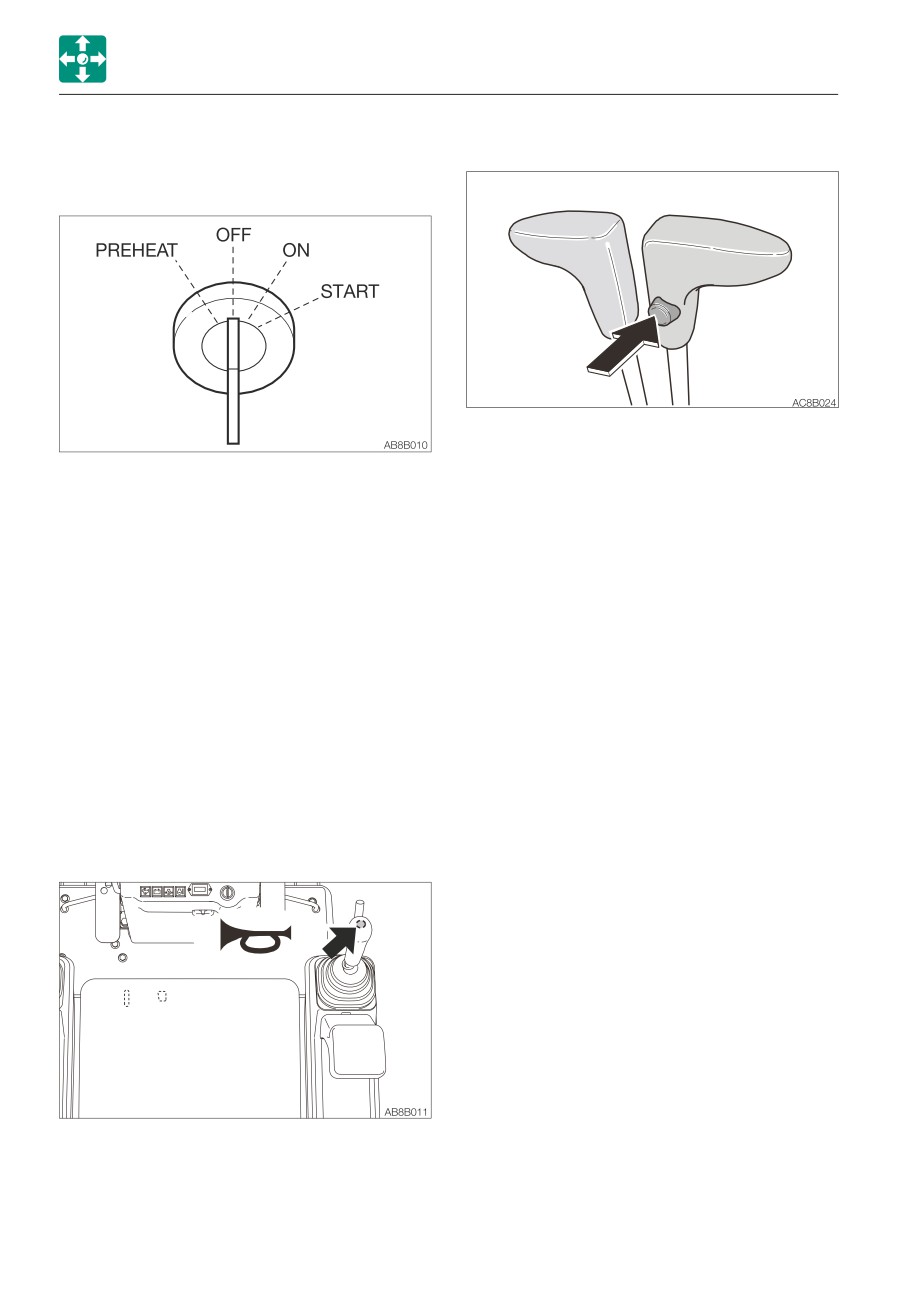
STARTER SWITCH
Press this switch to set the travel speed to
2nd (high) speed. Press it again to return to
IMPORTANT: Do not repeatedly switch
1st (low) speed.
the key from OFF to ON and ON to OFF
over a short period. Doing so will cause
engine breakdown.
PREHEAT Position for preheating the engine.
OFF
Position for stopping the engine
and inserting or removing the key.
ON
Position in which the engine is
running. At this position, all the
electrical equipment is functional.
START Position for starting the engine.
When the key is released, the
switch automatically returns to the
ON position.
HORN BUTTON
Press the button situated on the right
operating lever to blow the horn.
2-12
CONTROLS
SWITCHES
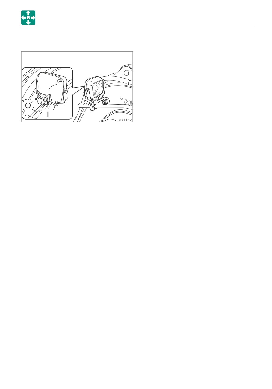
BOOM LIGHT
When the switch is pressed while the starter
switch is at ON, the light turns on or off as
follows:
O
Off
I
On
2-13
CONTROLS
LEVERS AND PEDALS
Safety start function <Applicable machine
LEVERS AND PEDALS
models 211003145 or later>
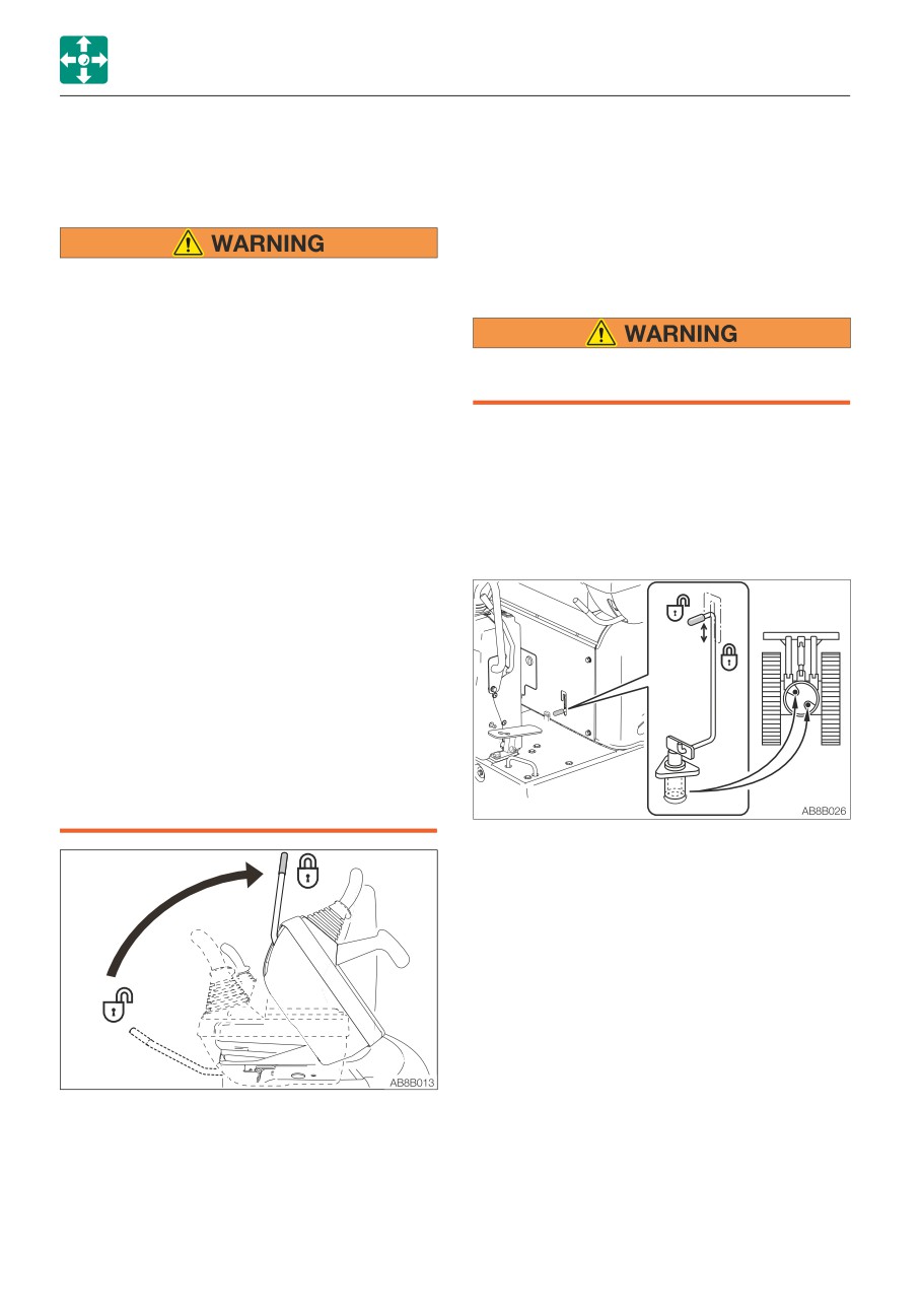
SAFETY LOCK LEVER
When the lever is in the unlock position, the
engine cannot be started.
• Before standing up from the operator’s
SLEW LOCK LEVER
seat to, for example, adjust the
operator’s seat, lower the working
equipment to the ground, raise the
safety lock lever to the lock position and
Engage the slew lock when traveling,
then stop the engine. If any control is
parking or transporting the machine.
accidentally touched when the safety
lock levers is lowered (unlocked), the
IMPORTANT: Do not try to slew when the
machine will suddenly move and cause
slewing is locked.
serious injury or death.
IMPORTANT: Unless the upperstructure
• Note that the dozer blade, boom swing
and the travel frame are aligned in
and auxiliary hydraulic controls cannot
parallel, slewing cannot be locked even
be locked, even when the safety lock
the lever is turned to the locked position.
lever is set to the locked position.
Do not carelessly touch these controls.
• Be careful not to touch the operating
levers when raising or lowering the
safety lock levers.
• Before leaving the operator’s seat, lower
the working equipment to the ground,
raise the safety lock levers to engage
the lock and stop the engine. Also, be
sure to remove the key, lock the door
and covers, take it with you and store it
in a specified place.
Use this lever to prevent the upperstructure
from slewing.
• Align the upperstructure in parallel with the
travel frame.
• To release the lock, turn the lever to the
upper position.
• To lock the slewing operation, turn the lever
to the lower position.
This device is for locking the hoe attachment,
slewing and traveling.
When the lever is raised, the lever stand
springs up and the controls are locked.
• Locking is possible by operating only one
side.
• To unlock, both sides must be operated.
2-14
CONTROLS
LEVERS AND PEDALS
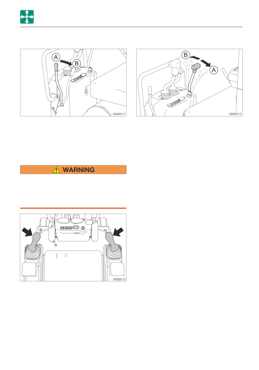
THROTTLE LEVER
BLADE LEVER
This controls the engine speed.
Use this lever to operate the dozer blade.
(A)
Low idling
(A)
Blade up
(B)
Maximum speed
(B)
Blade down
Refer to “Operating the dozer blade” on
page 3-17.
OPERATING LEVERS
• Before starting operation, carefully
check which lever pattern you are going
to use.
• It is described using the ISO pattern in
this manual.
Use these levers to operate the boom, arm,
bucket and upperstructure.
Refer to “Lever pattern” on pages 3-6 and
3-7.
Refer to “Operating the working equipment”
on pages 3-16 and 3-17.
2-15
CONTROLS
LEVERS AND PEDALS
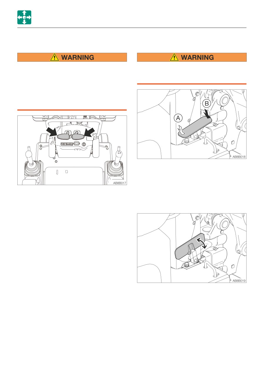
TRAVEL LEVERS
BOOM SWING PEDAL
Before operating the travel levers, make
Fold the pedal away when not in use.
sure that the dozer blade is to the front of
Stepping on a pedal accidentally when it
the operator’s seat. Remember that when
is not folded away may cause accidents.
the dozer blade is to the rear of the
operator’s seat, the travel levers must be
operated in the reverse direction from
when the blade is to the front.
Use this pedal to operate the boom swing.
(A)
Boom swing right
(B)
Boom swing left
Refer to “Operating the boom swing” on
Use these levers to move forward or
page 3-17.
backward and to change directions.
Refer to “Operating the travel levers” on
Folding the pedal
page 3-12.
Unfold the pedal when operating the pedal.
Fold the pedal away when not being used.
2-16
CONTROLS
LEVERS AND PEDALS
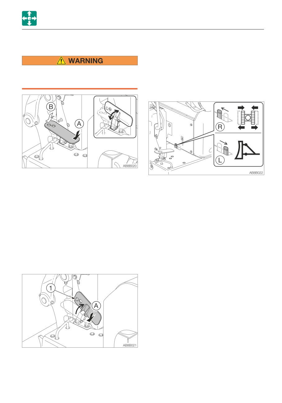
AUXILIARY HYDRAULIC PEDAL
1. Fold the pedal away while it is being
pushed into the side (A).
2. Pass the pedal hole through the bolt (1) to
fasten the pedal.
Fold the pedal away when not in use.
3. Unfold the pedal to unfasten it.
Stepping on a pedal accidentally when it
is not folded away may cause accidents.
SELECTOR LEVER
This pedal controls the flow of the oil in the
auxiliary hydraulic circuit.
This lever is used to change the crawler
(A)
Hydraulic oil flows to left auxiliary
width. The operation of the dozer blade
hose.
cylinder and the span cylinder is switched
(B)
Hydraulic oil flows to right auxiliary
with this lever.
hose.
1. To change the crawler width, first turn this
Refer to “Auxiliary hydraulic lines” on page
lever to the (R) position, then move the
2-19.
blade lever.
·
(R): Operation of spanner cylinder
Folding the pedal
·
(L): Operation of blade cylinder
Unfold the pedal when operating the pedal.
Fold the pedal away when not being used.
Fasting the pedal
The pedal can be fastened while in the
operating state. When using a hand breaker,
you can turn on or off the pedal by using the
switch on the breaker.
2-17
CONTROLS
ACCESSORIES
ACCESSORIES
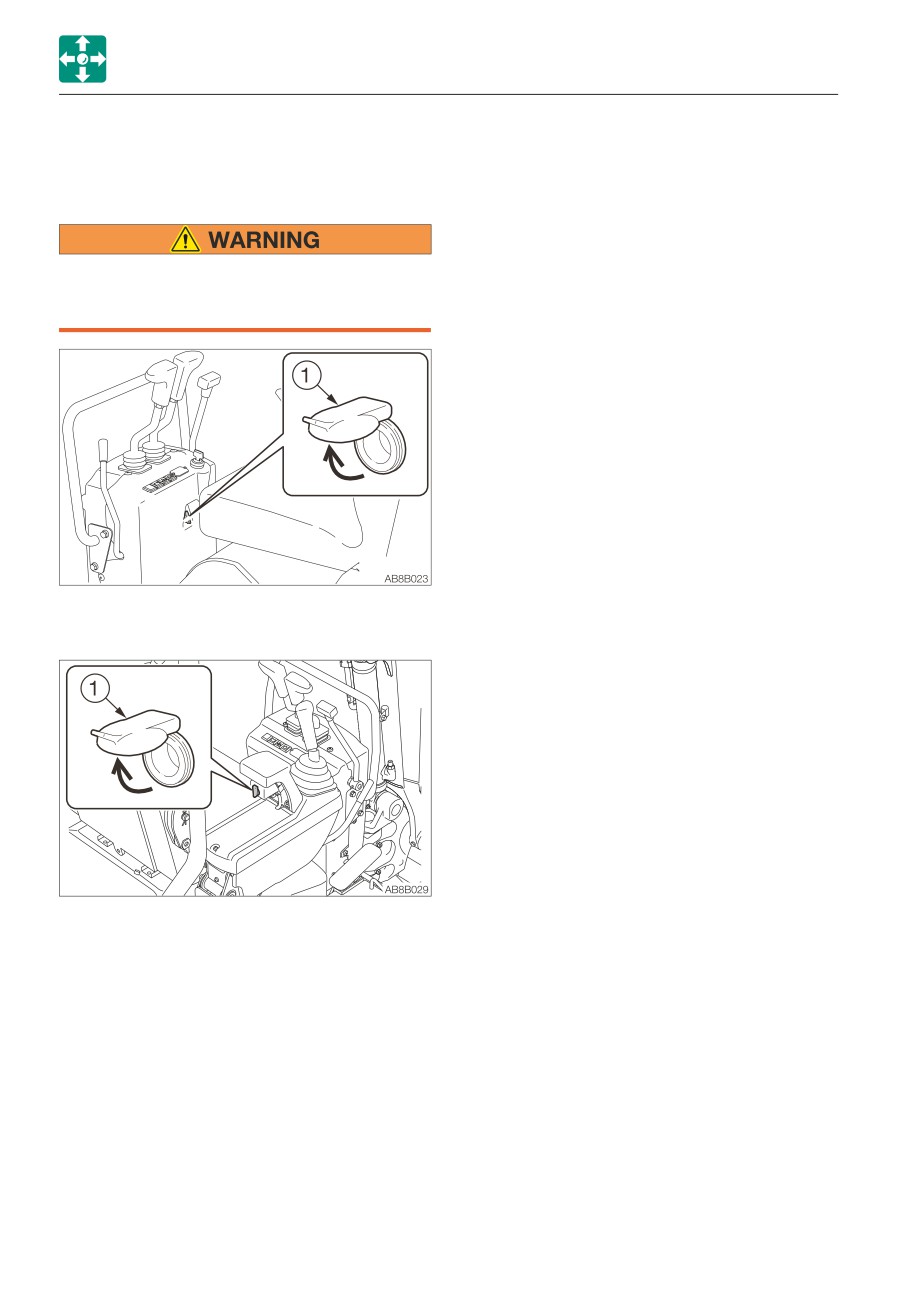
POWER SUPPLY SOCKET
Use only those electric products which
comply with the specifications of this
socket.
For beacon (If equipped)
This socket is used to supply power. Be sure
to use this socket for devices which require
power supply voltage/current less than
12V/5A.
To use, open the cap (1).
2-18
CONTROLS
ACCESSORIES
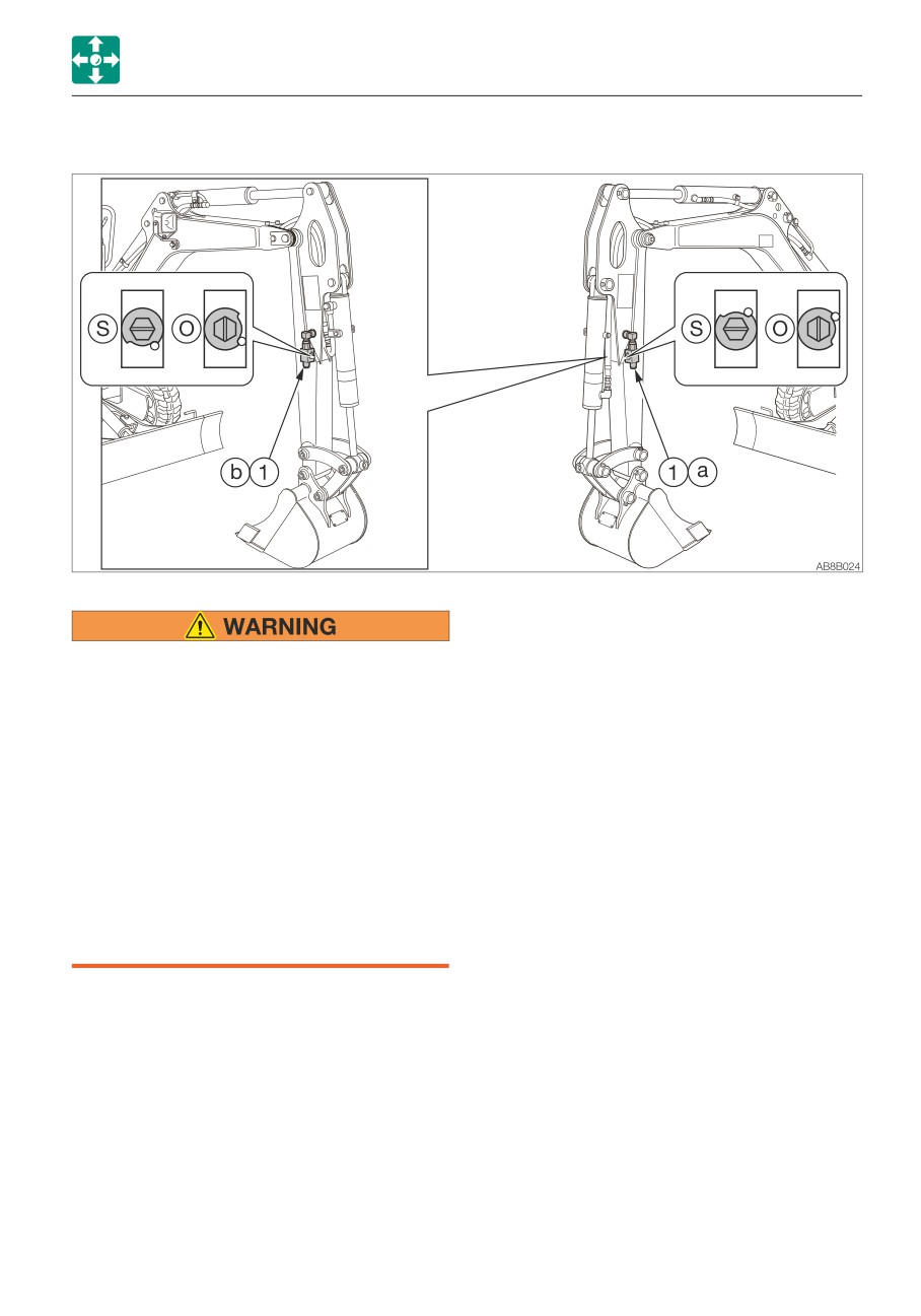
AUXILIARY HYDRAULIC LINES
This line delivers the hydraulic oil necessary
for operating a hydraulic breaker, crusher or
Oil may spurt out if pipes disconnected
other attachments.
before releasing the pressure in the
hydraulic system.
(1)
Auxiliary hydraulic line
• Step on each auxiliary hydraulic pedal
several times to release the residual
Stop valve
pressure from the auxiliary hydraulic
(S) : Close
circuits.
(O) : Open
• Slowly loosen the air bleeding plug to
relieve the internal pressure of the
hydraulic oil tank.
• When disconnecting hoses, stand to the
side and loosen them slowly to
gradually release the internal pressure
before removing.
2-19
CONTROLS
ACCESSORIES
Connecting the hydraulic circuits
Disconnecting the hydraulic circuits
To connect the attachment hydraulic lines,
1. Release the pressure remaining in the
observe the following procedures:
lines, and then close the stop valve.
1. Release the pressure remaining in the
Refer to “Releasing the residual pressure”
lines, and then close the stop valve.
on pages 2-20 and 2-22.
Refer to “Releasing the residual pressure”
2. Disconnect the lines from the ports (a) and
on pages 2-20 and 2-22.
(b).
2. Remove the plugs.
3. Install the plugs.
3. Connect the attachment hydraulic lines to
ports (a) and (b). When installing a
Operating
hydraulic breaker, connect the supply
circuit to the port (a) and the return circuit
to port (b).
4. Open the stop valves. When installing a
hydraulic breaker, open the selector valve
(1). Refer to “Selector valve” on page
2-21.
5. When connecting is complete, purge air
from the hydraulic lines.
a. Start the engine and run it at a low idle
speed with no load for 10 minutes.
b. With the engine running in low idle,
operate the auxiliary hydraulic pedal
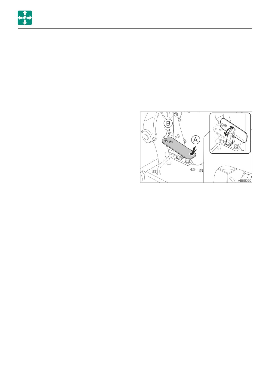
Press this pedal to control the flow of the oil
repeatedly (approx. 10 times) to purge
in the auxiliary hydraulic lines.
air from the hydraulic lines.
(A)
Hydraulic oil flows to left auxiliary line
c. Stop the engine and wait for at least 5
(a).
minutes until bubbles escape from the
(B)
Hydraulic oil flows to right auxiliary line
hydraulic oil in the tank.
(b).
IMPORTANT: Follow the procedures for
Releasing the residual pressure
purging air as instructed by the
After the auxiliary hydraulic circuits have
attachment manufacturer, if applicable.
been used, pressure remains in the circuits.
This is called the residual pressure. Release
6. Check for oil leaks.
this residual pressure before disconnecting
the lines.
1. When the engine is stopped, depress the
auxiliary hydraulic pedals back and forth
several times.
2-20
CONTROLS
ACCESSORIES
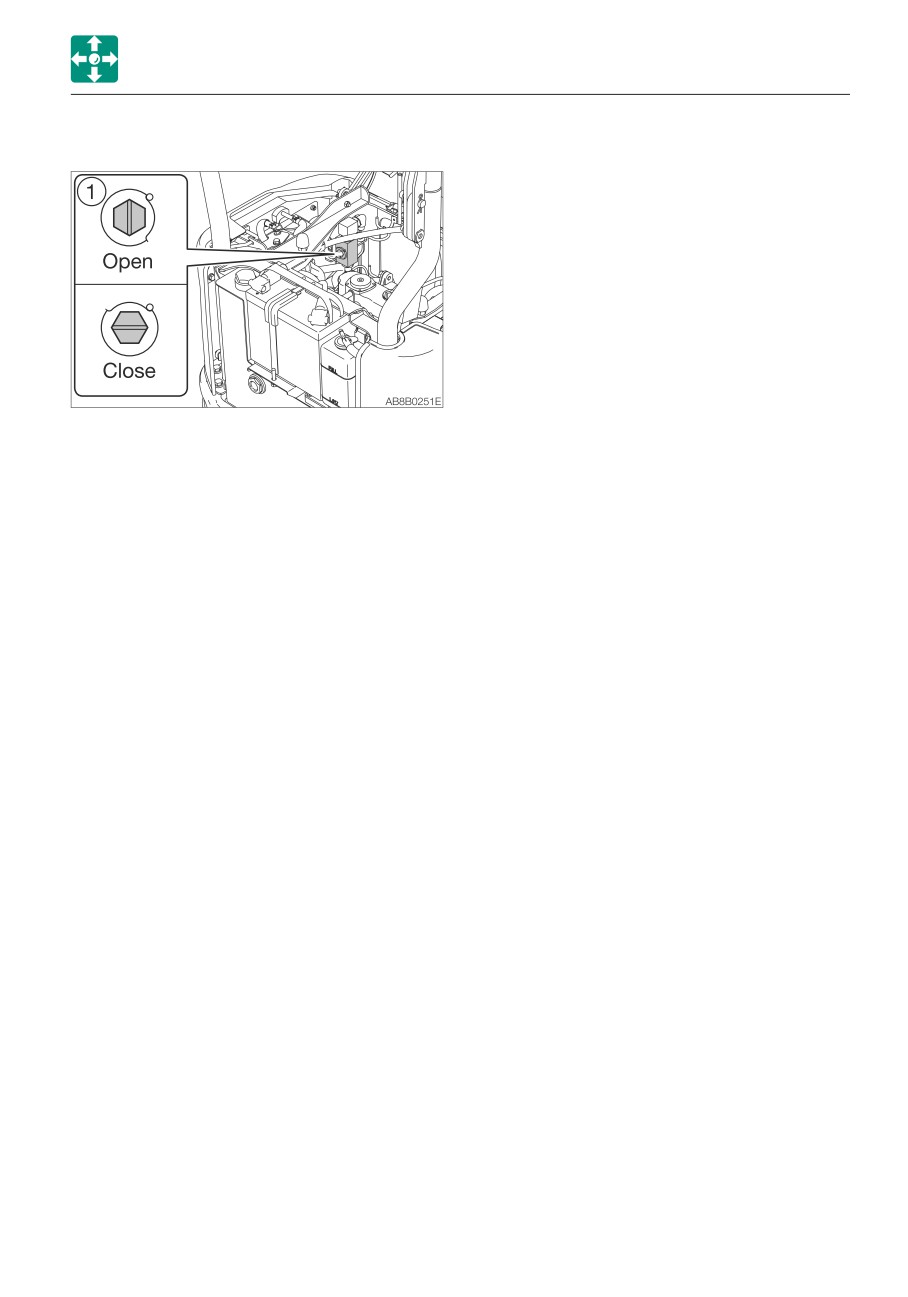
Selector valve
Open
When using a hydraulic breaker
(1-way flow)
Close
When using a reversible
attachment (2-way flow)
Change the direction of the hydraulic oil flow
by opening or closing the selector valve (1)
on the machine body.
2-21
CONTROLS
ACCESSORIES
ACCUMULATOR (IF EQUIPPED)
Operating the machine with an
accumulator
Be sure to handle the high-pressure
nitrogen gas enclosed in the accumulator
with care. If handled incorrectly, it could
explode and cause serious injury. Strictly
observe the following precautions:
6. Move all the control levers and pedals
• Do not disassemble.
several times in all directions to release the
• Do not allow flame near or throw it into
pressure from the working equipment
a fire.
circuitry.
• Do not drill, weld or fuse.
7. Raise the safety lock lever to engage the
• Do not subject it to physical shock such
lock.
as hitting, rolling or dropping.
• Before disposing of the unit, the sealed
Lowering the boom when the engine has
gas must be drained. Contact a
stopped
Takeuchi service agent for help.
Perform this operation within 10 minutes
after the engine stopping.
For a machine with an accumulator, the
1. Check that the safety lock lever is in the
residual pressure in the auxiliary hydraulic
released position.
circuit or the working equipment circuit can
2. Check that the starter switch is in the ON
be released even after the engine is stopped.
position.
3. Slowly push the operating lever forward to
Releasing the residual pressure
lower the boom.
Residual pressure refers to the pressure that
remains in the hydraulic circuit after the
operation. Release the residual pressure as
necessary by using the following steps.
Perform the residual pressure releasing
within 10 minutes after the engine stopping.
1. Return the throttle lever to idle the engine
at low speed.
2. Lower the bucket and dozer blade to the
ground.
3. Check that the safety lock lever is in the
released position.
4. Stop the engine.
5. Turn the starter switch to the ON position.
2-22
OPERATION
3-1
OPERATION
BEFORE STARTING OPERATION
WALK-AROUND INSPECTION
BEFORE STARTING
Perform the walk-around inspections once a
OPERATION
day before starting the engine for the first
GETTING ON OR OFF THE MACHINE
time that day.
Refer to “MAINTENANCE, Walk-around
inspection”, on pages 5-14 and 5-15.
• Do not jump on or down from the
machine. Never attempt to get on or off
DAILY INSPECTION
the moving machine.
Perform the daily inspections once a day
before starting the engine for the first time.
Refer to “MAINTENANCE, Daily inspection”,
on pages 5-16 to 5-21.
• Climb up/down the steps holding the
handrail to support your weight in a
three point secure stance (hand and
feet).
• Never use the safety lock lever or
control levers as hand holds.
3-2
OPERATION
STARTING AND STOPPING THE ENGINE
5. Insert the key into the starter switch, turn it
STARTING AND STOPPING
to the ON position, then perform the
following inspections:
THE ENGINE
BEFORE STARTING THE ENGINE
1. Adjust the seat for a comfortable operating
position.
2. Fasten the seat belt.
· The battery charge warning lamp (1) and
the engine oil pressure warning lamp (2)
light up.
· Press the switch at the rear of the boom
light to check if it turns on.
3. Check that the safety lock lever is in the
If either lamp does not light up, the bulb may
locked position.
be burnt out or a wire may be damaged. Ask
your sales or service dealer for repair.
4. Check that all levers and pedals are in the
neutral position.
3-3
OPERATION
STARTING AND STOPPING THE ENGINE
STARTING THE ENGINE
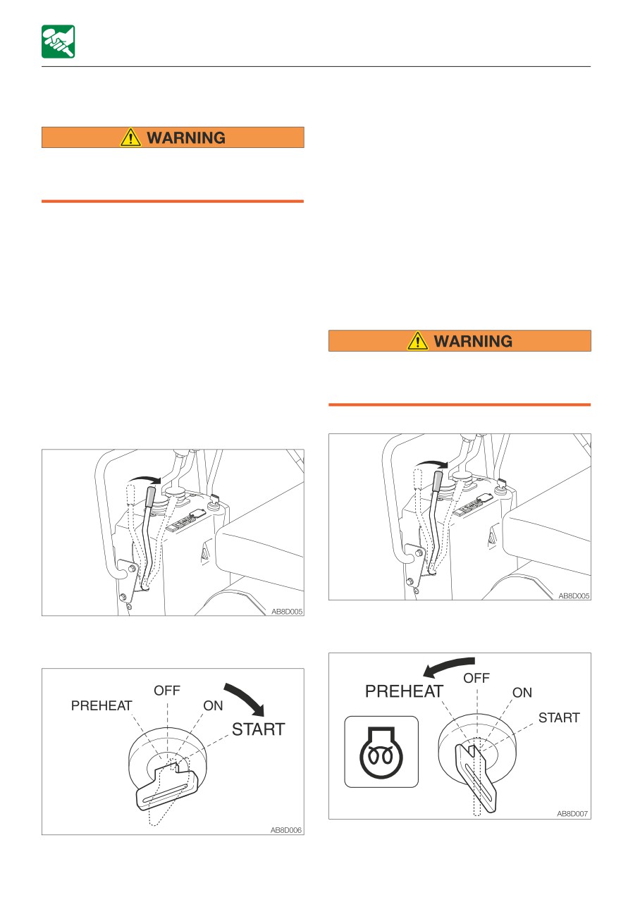
When the machine is equipped with the
safety start function: The engine does not
start unless the safety lock lever is in the
locked position at this point.
• Clear all personnel from the work area.
Refer to “Safety lock lever” on page 2-14.
• Sound the horn to warn people around
3. Once the engine starts, release the key.
the machine.
The key automatically returns to the ON
position.
IMPORTANT: Do not run the starter motor
4. Check that the warning lamps are off.
for more than 15 consecutive seconds. If
5. Return the throttle lever and warm up the
the engine fails to start, wait for 30
engine.
seconds, and then try again to start the
Refer to “Warming up the engine” on page
engine.
3-5.
IMPORTANT: If the engine stalls due to
fuel shortage, add fuel, turn the key to the
Starting in cold climates
ON position for 60 seconds, and then turn
it to the START position. Running the
starter for a long time before there is
Never use starting fluid on this engine, as
enough fuel is going through can cause
the starting fluid could cause an
the starter to fail.
explosion.
Normal starting
1. Pull the throttle lever to the middle
1. Pull the throttle lever to the middle
position.
position.
2. Turn the starter key to the PREHEAT
2. Turn the starter key to the START position
position and hold it for about 5 seconds.
and start the engine.
3-4
OPERATION
STARTING AND STOPPING THE ENGINE
When the coolant temperature is -5 to
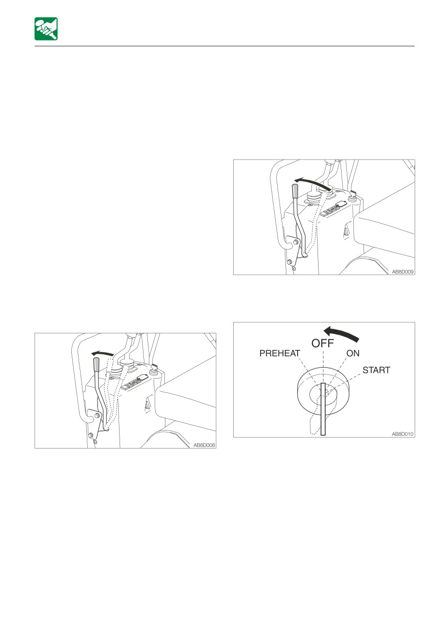
STOPPING THE ENGINE
10°C (23 to 50°F).
When the coolant temperature is at or
IMPORTANT: Do not stop the engine
below -5°C (23°F), hold it for about 10
suddenly when operating with heavy
seconds for preheating.
loads or at the maximum speed. Doing so
3. After preheating, turn the key to the
may cause the engine to overheat or
START position and start the engine.
seize. Never stop running the engine
4. Once the engine starts, release the key.
suddenly except in emergency.
The key automatically returns to the ON
position.
5. Check that the warning lamps are off.
6. Return the throttle lever and warm up the
engine.
Refer to “Warming up the engine”.
WARMING UP THE ENGINE
IMPORTANT: Avoid racing the engine until
it has warmed up.
Do not warm up the engine for a long time
1. Return the throttle lever.
(20 minutes or more). When idling is
2. Idle the engine with no load for about 5
required, occasionally place a load or run
minutes to gradually let it cool.
the engine at medium speed.
3. Turn the starter key to the OFF position to
1. Return the throttle lever, then run the
stop the engine.
engine at a low idle speed with no load for
5 minutes.
3-5
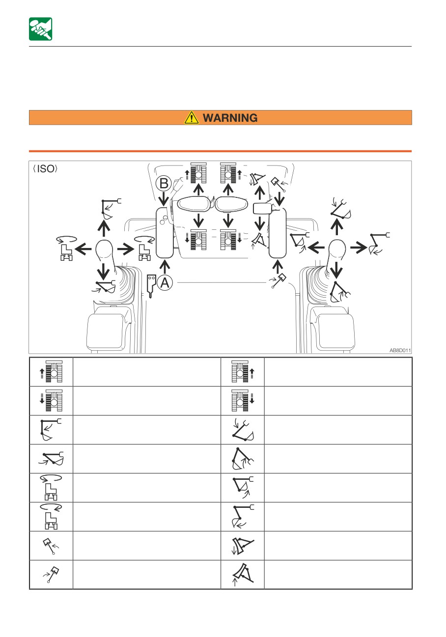
OPERATION
OPERATING THE MACHINE
OPERATING THE MACHINE
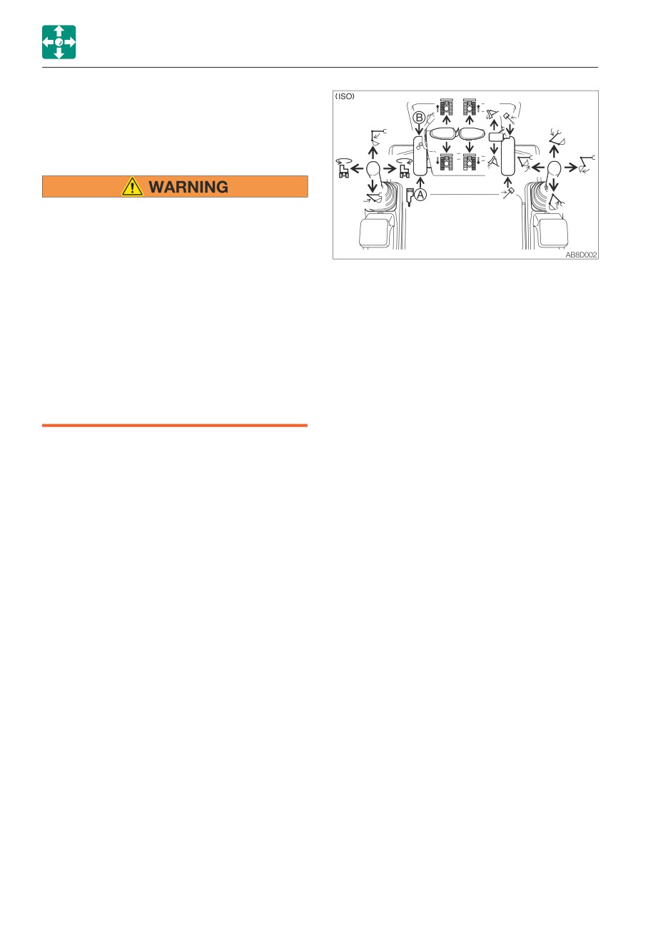
LEVER PATTERN (ISO PATTERN)
• Before starting operation, carefully check which lever pattern you are going to use.
• It is described using the ISO pattern in this manual.
Left crawler forward
Right crawler forward
Left crawler reverse
Right crawler reverse
Arm out
Boom lower
Arm in
Boom raise
Upperstructure slew left
Bucket load
Upperstructure slew right
Bucket dump
Boom swing left
Dozer blade lower
Boom swing right
Dozer blade raise
3-6
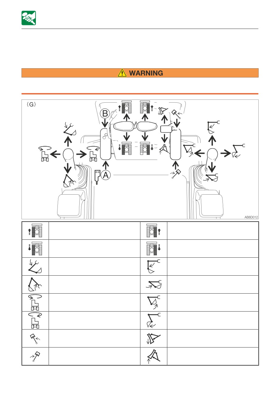
OPERATION
OPERATING THE MACHINE
LEVER PATTERN (G PATTERN) (IF EQUIPPED)
• Before starting operation, carefully check which lever pattern you are going to use.
• It is described using the ISO pattern in this manual.
Left crawler forward
Right crawler forward
Left crawler reverse
Right crawler reverse
Boom lower
Arm out
Boom raise
Arm in
Upperstructure slew left
Bucket load
Upperstructure slew right
Bucket dump
Boom swing left
Dozer blade lower
Boom swing right
Dozer blade raise
Refer to “Selecting a lever pattern” on page 8-5.
3-7
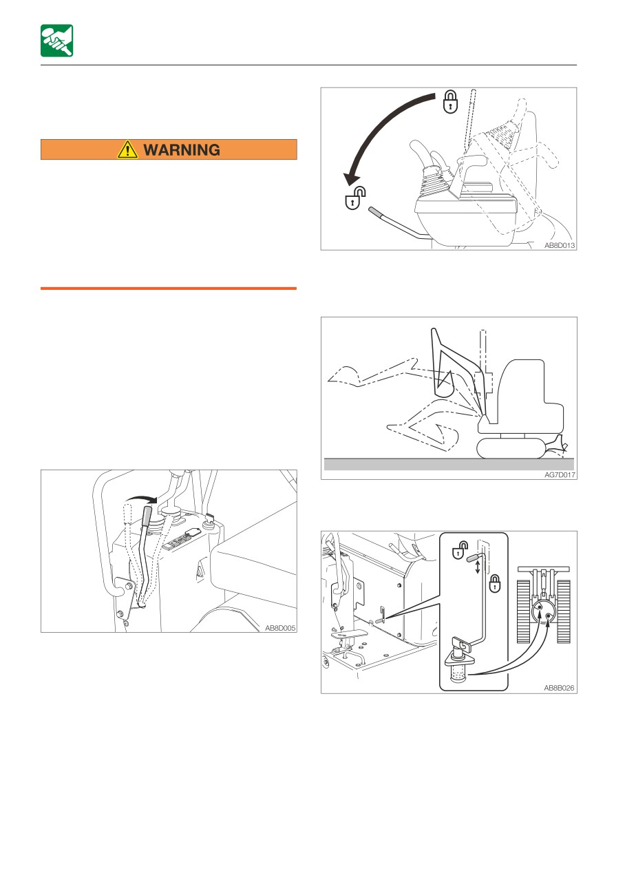
OPERATION
OPERATING THE MACHINE
WARMING UP THE MACHINE
(HYDRAULIC OIL)
Operating the working equipment without
warming up the machine (hydraulic oil) is
dangerous, as the working equipment
cannot response to controls quickly or
may move in unexpected ways, and the
safety devices may not operate properly.
Be sure to sufficiently warm up the
2. Fully lower the safety lock lever to
machine.
disengage the lock and lift the bucket from
the ground.
IMPORTANT: Do not operate the levers
too quickly when the hydraulic oil
temperature is below 20°C (68°F). The
proper hydraulic oil temperature during
operation is 50 to 80°C (122 to 176°F). If
operations must be performed at lower
temperatures, heat up the hydraulic oil to
at least 20°C (68°F).
Normal warm-up
3. Extend and retract each of the cylinders
slowly several times with no load.
1. Pull the throttle lever to the middle
position, then run the engine at medium
speed for about 5 minutes with no load.
4. Set the slew lock lever to the released
position before slewing.
3-8
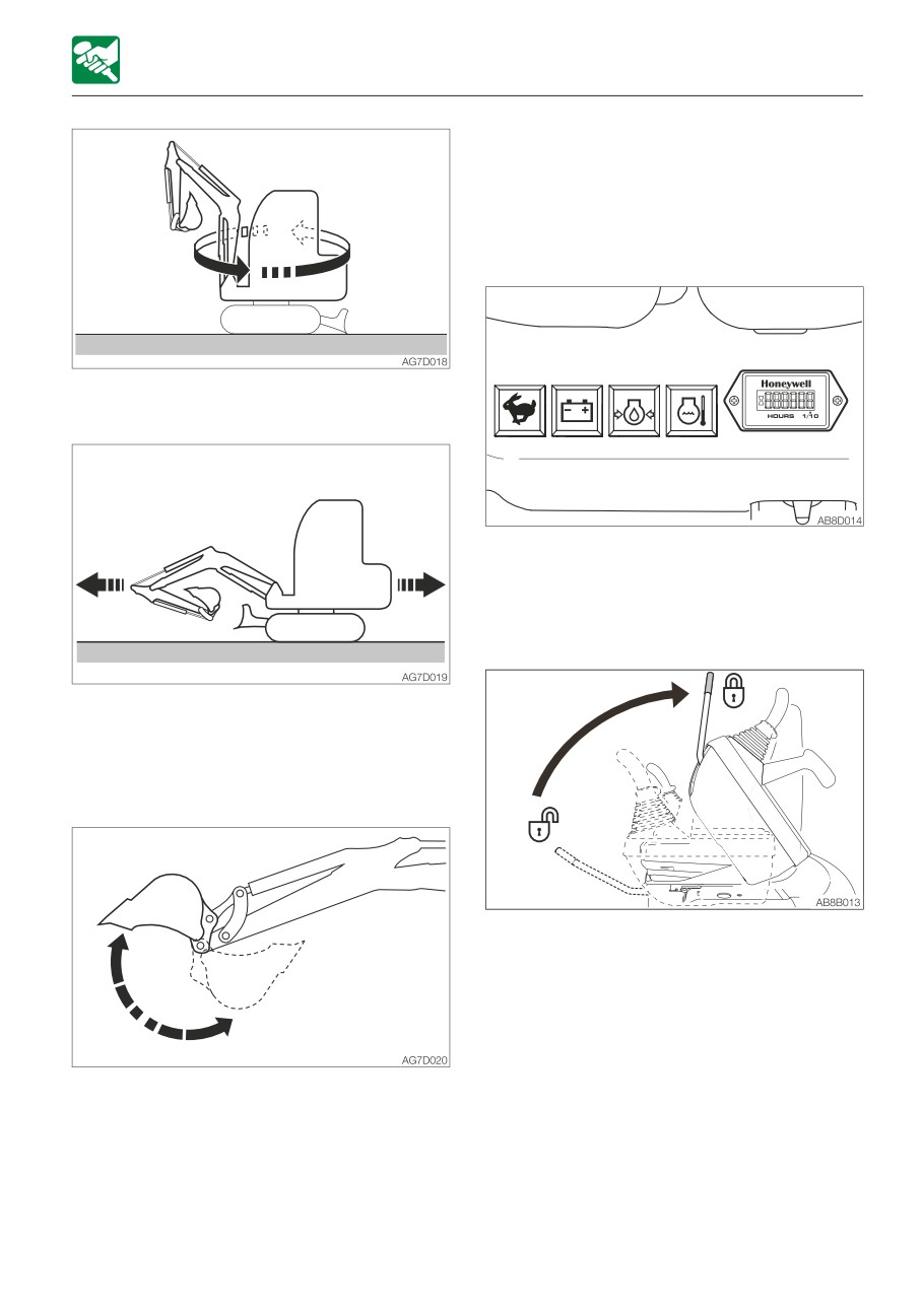
OPERATION
OPERATING THE MACHINE
INSPECTION AFTER WARM-UP
After warming up the engine and machine
(hydraulic oil), perform the checks and
inspections described below, and repair if
necessary.
5. Slew slowly to the left and the right several
times.
1. Check that the warning lamps and meters
are as follows:
· Are all warning lamps off?
2. Check that there are no irregularities in the
exhaust color, sound and vibrations.
6. Travel slowly forward and in reverse
several times.
Warm-up in cold climates
1. Perform the normal warm-up procedure.
3. Raise the safety lock lever to the locked
position, and then check that the
operating and travel levers are locked.
2. Set the bucket cylinder at the stroke end
and keep it there.
Do not keep this condition for more than
30 seconds.
3. Repeat Step 2 until the bucket operating
speed becomes normal.
3-9
OPERATION
OPERATING THE MACHINE
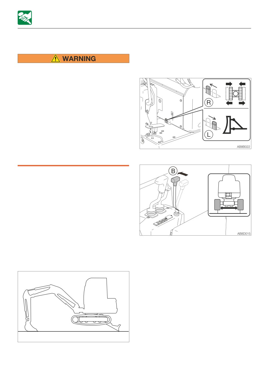
CRAWLER WIDTH SWITCHING
IMPORTANT: Be sure to raise the machine
body before switching the crawler width.
If the operation is attempted when the
crawler is rested on the ground, the travel
Operate the machine with the maximum
frame or span cylinder may be damaged.
crawler width
• Always operate the machine with the
crawler width extended to 1020 mm
(40.2 in.) to maximize the machine
stability. If the machine is operated with
the crawler width narrowed (750 mm,
29.5 in.), the machine may tip over due
to its poor stability.
• If the machine must be operated with
the narrowed crawler width (750 mm,
29.5 in.), traveling should be done after
folding the hoe attachment, lowering the
boom to lower the center of gravity and
2. Turn the selector lever to the (R) side.
keeping the machine facing forward.
IMPORTANT: All debris, mud, soil, stones,
etc. must be removed from the track
frame before switching the crawler width.
Do it in a safe manner and do not work
under the machine.
This machine is able to change the crawler
width. Normally, it is best to operate with the
crawler width extended for machine’s
stability.
3. Push the blade lever forward (B) to
Switching the crawler width
increase the crawler width (1020 mm or
Perform the operation on a flat and rigid
40.2 in.).
ground where no obstacles around.
If necessary, extend the blade width by
changing the plate (2).
Refer to “Switching the blade width” on
page 3-11.
AD6D012
1. Raise the machine body by using the hoe
attachment and the dozer blade.
3-10
OPERATION
OPERATING THE MACHINE
SWITCHING THE BLADE WIDTH
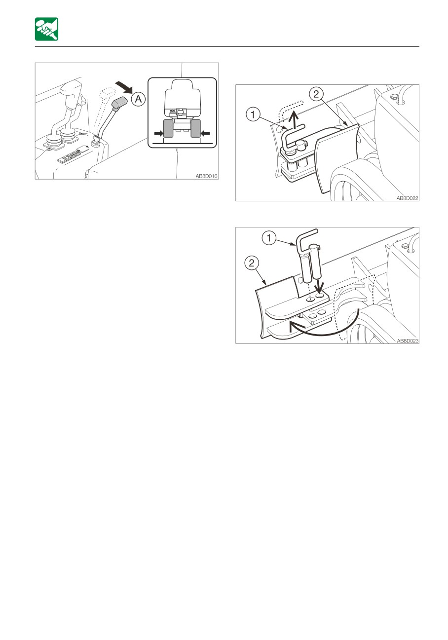
4. Pull the blade lever toward you (A) to
decrease the crawler width (750 mm or
29.5 in.).
1. Pull out the lock pin (1).
2. Rotate the plate (2).
3. Insert the lock pin (1) to secure the plate
(2).
3-11
OPERATION
OPERATING THE MACHINE
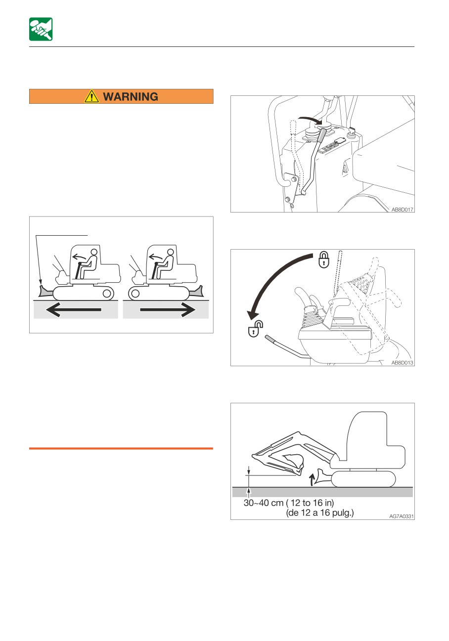
OPERATING THE TRAVEL LEVERS
Moving the machine forward and
backward
• Never allow anyone to enter the
machine’s slewing radius and path.
• Signal your intention to move by
sounding the horn.
• There is a blind spot in the rear of the
machine. Before traveling in reverse, as
necessary, swing the cab around in
reverse to check that the area is safe
and clear.
1. Pull the throttle lever and increase the
Dozer blade
engine speed.
AG7A032PE
• Before operating the travel levers, make
sure that the dozer blade is to the front
of the operator’s seat. Remember that
when the dozer blade is to the rear of
2. Fully lower the safety lock lever to
the operator’s seat, the travel levers
disengage the lock.
must be operated in the reverse
direction from when the blade is to the
front.
• Clear all obstacles from the path of the
machine.
3. Fold the hoe attachment and lower it 30 to
40 cm (12 to 16 in.) above the ground.
4. Lift the dozer blade.
5. Operate the left and right travel levers as
below.
3-12