SiteSentinel Automated Monitoring System Model 2 and Model 3. Operator Manual Software Version 1.12CUS - part 2
SiteSentinel
IMPORTANT
Manifolded tanks are physically connected so that product can flow freely between them. A
probe is required for each tank in the manifold group. All probes for a manifold group must be
connected to the same Smart Module.
To set up a group of manifolded tanks, first use the SENSOR & PROBE CONFIGURATION
MENU to configure each probe in the group. Items 5 and 6 can be entered for the group as a
whole from the TANK MANIFOLDING MENU and do not need to be assigned individually. After
the probes are configured, assign positions to a group.
Note that if you use the SENSOR & PROBE CONFIGURATION MENU to change items 5 and/or
6 for a position after it is assigned to a manifold group, all positions in the group are changed
automatically.
DESCRIPTION
This is a label that can be used to describe the device at this module position. For example,
`SUMP SENSOR' or `NORTH SUMP'.
64
System Setup
PRODUCT
You can enter a label to identify the monitored product. This feature does not select the type of product
to be monitored (see next section).
PRIVILEGED MODE
JUN 26, 1996
8:36 AM
SENSOR & PROBE CONFIGURATION
1.MODULE: 1
POSITION: A PROBE
2.RECONFIGURE (3-12)
3.TANK#:
1
4.DESCRIPTION:
12-FOOT PROBE
5.PRODUCT:
DIESEL
6.API/DENSITY/ALPHA:
34.4
TEMPERATURE:
60.0 F
HYDROMETER:
NONE
7.TANK SHAPE:
CYL-ROUND ENDS
8.TANK DIAMETER:
92.0000 IN
9.TANK VOLUME:
10000.0000 GAL
10.PRODUCT OFFSET:
0.0000 IN
11.WATER OFFSET:
0.0000 IN
12.WATER FLOAT:
USED-ENABLED FOR PROBE ERR
13.DELIVERY TIMER:
0 MIN.
ENTER #, C/CANCEL, H/HELP OR 0/PRINT:
PROBE CONFIGURATION
Whenever menu items 5 - 12 are reconfigured, the event history buffer is cleared.
MODULE & POSITION
Select this item to specify which module and position to configure. The menu above shows the prompts
for a probe.
Before you enter configuration data for a probe, you must first assign it to a module and position.
After you enter probe configuration data, you must also enter tank threshold data. All probe module
positions must also be installed.
65
SiteSentinel
RECONFIGURE
Select this item to specify data for all features. To prompt for a single feature, enter the corresponding
number from the menu (3 - 12).
TANK #
The number of a tank is not determined by the module or position number to which the corresponding
probe is wired at the Smart Module. The tank number is only a label that is used to identify the tank for
the reports.
DESCRIPTION
This is a label describing the device at this module position. For example, `HYDROCARBON SENSOR' or
`PV PROBE'.
PRODUCT
This is the name that is used for the product on the reports. This name is only a label.
API/DENSITY/ALPHA
The API (American Petroleum Institute) number is a measure of a product's density. The SiteSentinel
uses the API number to determine the product's expansion coefficient. This value is used to standardize
the effect of product temperature on product volume. The API number for a product can usually be
obtained from the product distributor.
(The SiteSentinel accepts only API numbers between
0EAPI and 85EAPI).
API numbers for some common liquids are shown below:
Regular Gasoline
63.0
Unleaded Gasoline
60.0
Premium Unleaded Gasoline . 66.0
Diesel
47.0
Kerosene
43.0
The product density can be substituted for the API number. The range for density values is 654 to 1075
kg/m3. (The density of a product is equal to the specific gravity multiplied by 999.) The SiteSentinel
automatically determines whether an entry is an API number or density value by the range in which it
falls.
66
System Setup
For products other than motor fuel, heating and diesel oils, jet fuels, kerosene and gasoline, a thermal
expansion coefficient - Alpha - should be substituted for the API number.
For more information on API numbers, density, and Alpha values, see Page 57.
IMPORTANT
A standardized API or density value for a product must be calculated at a reference temperature.
For API numbers, the reference temperature is usually 60EF. For density, the reference
temperature is
15EC or 20EC. Use the Controller Setup menu to change the reference
temperature.
If you measure the API or density value directly (using a hydrometer), you must also determine the
current product temperature.
Procedure
1. Enter an API, density, or Alpha value
If an Alpha value is entered, no further information is needed.
2. If an API or density value is entered, you'll be prompted for the temperature at which the reading
was taken:
If no temperature is entered, the reference temperature is used.
3. If a temperature is entered, you are next prompted as to whether you used a glass hydrometer.
4. If a glass hydrometer was used, specify `GLASS'. If you did not use a hydrometer, specify
`NONE'. Use the [NO] or [N] key to toggle the options. When the appropriate option displays,
press the [ENTER] key.
TANK SHAPE
The SiteSentinel recognizes three tank types:
(1) Cylindrical with flat ends
(typical steel tank)
(2) Cylindrical with rounded ends
(typical fiberglass tank)
(3) Straight sides
(typical vertical tank)
67
SiteSentinel
Use the [NO] or [N] key to toggle the options. When the appropriate tank type displays, press the
[ENTER] key.
To correct for tank variations, refer to Page 79.
TANK DIAMETER
Most tanks have a nominal diameter (or height for vertical tanks) listed in the manufacturer's
specifications. The actual size of a tank can vary several inches from its supplied specification.
It is strongly recommended that the inside of each tank be measured carefully to ensure accurate
system data.
TANK VOLUME
The tank volume is determined from the nominal volume supplied by the manufacturer or from a
measured fill.
PRODUCT OFFSET
The product offset can be calculated and added to the probe offset to electronically "center" the probe
in a tank. No compensation factor is required if a tank is perfectly level or if the probe is installed at or
near the tank center.
To determine the product offset, it is necessary to make a few measurements and a few simple
calculations. The measurements are easier to make during installation and should already have been done.
If not, the procedure for determining the compensation value is described in the Installation Manual.
WATER OFFSET
To calculate the water offset, you should manually measure the amount of water (usually by sticking the tank).
The system measurement is then subtracted from this value to yield the water offset.
For example, a tank has a stick measurement of 0.4" of water. The water level in the tank inventory report is 3.1".
The water offset should be -2.7". After entering the offset, the inventory report will show the corrected water level
and volume.
The magnet in the water float (which marks the float's position for the controller) is located about 2.7" (7 cm) from
the bottom of the float. As a result, the system will show a water level even when there is no water in the tank,
unless you enter a water offset value.
68
System Setup
WATER FLOAT
Probes can be installed with or without a water float.
USED - ENABLED PROBE ERR The water float readings are based on actual float position and water offset
value.
USED - DISABLED FOR PROBE ERR. The water level displayed is equal to the level just prior to the
water float error. If during the time since the error, the product level has dropped below the last water
level, then the water level displayed is equal to the product level.
NOT USED. The water level is unavailable.
DELIVERY TIMER
Enter a time to allow product in a tank to “settle down” after a delivery. Turbulence will occur during
and shortly after product is pumped into a tank, sometimes causing erroneous readings. After this time
expires, normal probe monitoring begins.
Enter a time in minutes from 1 to 59.
69
SiteSentinel
3.2.3 Tank Manifolding Menu
MAIN MENU L Á L „ L Ó
SITE SENTINEL
OCT 31, 1994
8:36 AM
TANK MANIFOLDING MENU
1.MODULE:
1
2.MANIFOLD GROUP:
1
3.POSITIONS:
AB
4.PRODUCT:
UNLEADED
5.API/DENSITY:
60.0
TEMPERATURE:
60.0 F
HYDROMETER:
NONE
6.MIN. THEFT:
10.0000 GAL
7.MIN. SALE:
10.0000 GAL
8.MIN. DELIVERY: 20.0000 GAL
GROUP: POSITIONS:
1
AB
2
...D.F
3
..C.E
4
......GH
5
..........KL...P
6
........IJ
7
............MNO.
8
ENTER #, C/CANCEL, H/HELP OR 0/PRINT:
SETUP
Tanks can be physically connected together, or manifolded, so that product can flow freely between them.
Each tank in a manifolded group must have its own probe.
All probes for a manifold group must be connected to the same Smart Module.
Module positions must be configured before they can be assigned to a manifold group.
To set up a manifold group, specify the module number, manifold group, and positions. At least two
positions must be entered for a group to be valid. Positions do not need to be adjacent. Once a position
has been assigned to a group, it cannot be entered in another group.
The product label, API/density, temperature, hydrometer, and volume-activated thresholds (minimum
theft, sales, and delivery) are entered for the group as a whole. The level-activated tank thresholds values
(low product, overflow, and high water) can be set up for each tank in a manifolded group, but not for
the group as a whole (see next section).
70
System Setup
DATA
Data from a manifolded tank group is reported in a manner slightly different than the data from single
tanks.
The SiteSentinel generates saved and immediate inventory reports for both the manifolded group and
each tank in the group. Sales, thefts, and deliveries are reported only for the manifolded group as a whole.
Overflow, low product, high water, and bad temperature events are indicated for each individual tank in
the group.
Whenever product is added or removed from one manifolded tank, the volumes of all the tanks in the
group are affected for a period of several minutes to a half an hour.
71
SiteSentinel
3.2.4 Tank & Sensor Thresholds
MAIN MENU L Á L „ L Ô
SITE SENTINEL
JUN 26, 1996
8:36 AM
TANK & SENSOR THRESHOLDS
1.MODULE & POSITION: 1A PROBE
PROBE #:
DESCRIPTION:
2.HIGH WATER:
3.OVERFLOW:
4.LOW PRODUCT
5.MIN. THEFT:
6.MIN. SALE:
7.MIN. DELIVERY:
8.LEAK RATE:
9.COLD AVE. TEMP ON:
10.COLD AVE. TEMP OFF:
11.HIGH WATER TIMER:
ENTER #, C/CANCEL, H/HELP OR 0/PRINT:
Tank Thresholds
MODULE & POSITION
IMPORTANT
Select this item to specify the module and position for
Whenever the minimum theft, sale, and/or
which to enter threshold data. The menu prompts are
delivery values (menu items 5, 6, and 7) are
determined by which device was selected when the
module and position type were assigned. The current
changed for a position that is part of a
threshold values, if any, are displayed.
manifolded tank group, all positions in that
group are changed automatically.
Before you enter tank threshold data, you must first
assign its probe to a module and position (Page 58)
and enter tank configuration data.
All probe module positions must also be installed.
72
System Setup
HIGH WATER
Some water is present in most tanks due to condensation. Water also can leak into a tank if it is located
below the water table. Water is more dense than most fuel products and sinks to the bottom of a tank.
To prevent water from being pumped as product, the high water level should be set well below the
suction tube or pump intake. The high water value typically is six inches (15 cm) or less.
OVERFLOW
To prevent spillage due to excessive product deliveries, you can specify an overflow level. This value
should reflect both the size of the tank and the rate at which product is pumped.
This level should be set far enough below the actual point of overflow to allow for any delay between
flagging the overflow (which happens when the level is reached) and the actual stopping of product flow.
A typical value would be 90% of tank diameter (or height).
LOW PRODUCT
To prevent product shortages, you can specify a low product level to indicate when product is running
low. The level set should be based on the rate of product dispensed from the tank and lead times for
product delivery.
A typical value is 10% of tank diameter (or height).
IMPORTANT
MIN. THEFT
The SiteSentinel can define two operational
Set the minimum theft level to a small volume,
statuses for a system: "open" and "closed."
typically about five gallons (20 l).
When the system is open, product withdrawn
is considered to be authorized and is defined
MIN. SALE
as a "sale." When the system is closed,
product
withdrawn
is
considered
The SiteSentinel is designed to report every sale
unauthorized and is defined as a "theft."
for an active commercial site, such as a gas station.
Refer to System Commands for opening and
closing the system.
MIN. DELIVERY
Unless deliveries occur with uncommon frequency, this level can be set low enough to flag each delivery.
A typical value is ten gallons (40 liters). Sales, deliveries and thefts can not be distinguished if they occur
simultaneously. Refer to the Reports Section for more details.
73
SiteSentinel
LEAK RATE
The Leak Threshold value is used by the Timed Leak Test. Typical values for the threshold range from
0.05 to 0.1 gallons per hour (0.2 to 0.4 liters per hour).
This range allows the Timed Leak Test to detect volume changes of 0.1 to 0.2 gallons per hour (0.4 to
0.8 liters per hour) in accordance with U.S. EPA standards. For more details about the Timed Leak Test.
see Page 102.
COLD AVERAGE TEMP ON/OFF
Some fuels, particularly diesel, must be kept from “jelling” in cold climates.
Heaters are installed on some tanks for this purpose; the COLD AVERAGE settings control at what
temperature this heater goes ON and OFF. Enter two temperatures to create a range in which the heater
is ON:
When product temperature drops to the Cold Ave. Temp. ON setting, the heater goews ON. When
product temperature reaches the Cold Ave. Temp. OFF setting, the heater goes OFF.
HIGH WATER TIMER
When product is added to a tank, water in the tank will rise temporarily, until the turbulance caused by
delivery subsides.
This timer tells the water float to “ignore” a high water reading for a specific length of time you set. Enter
a value from 0 minutes to 59 minutes.
Entering “0" disables the timer, producing an immediate high-level reading.
74
System Setup
Sensor Thresholds
IMPORTANT
(1) The following require an upper threshold data entry:
Hydrocarbon Vapor: 0.1 volt above normal
Liquid (stand-alone sensor or water-sensing element of interstitial sensor):
0.1 volt above normal
Freon: 0.1 volt above normal
(2) The following have a fixed threshold (no threshold data entry required):
Universal Reservoir:
2.5 volts (upper threshold)
Hydrocarbon Liquid (interstitial and liquid phase): 1.0 volt (lower threshold)
Universal Sump: 2.5 volts (lower threshold)
Water (optional part of liquid phase sensor):
2.5 volts (lower threshold)
(3) A generic sensor must have both upper and lower threshold data entries. Either, neither, or both of these
thresholds can be disabled.
(4) A "normal" present value requires most sensors to be installed and operating in an uncontaminated
environment for at least two hours.
(5) To minimize false alarm indications, threshold alarm delays can be programmed for all types of sensors.
MODULE & POSITION
This choice specifies a module and position for which to enter threshold and/or alarm delay data. Menu
prompts are determined by which sensor was selected when the module and position type were assigned;
prompts for a vapor sensor are shown in the menu above.
Before entering threshold and/or alarm delay data, first assign a module and position to the sensor. After
entering threshold and/or alarm delay data, sensor module positions must also be installed (Page 58).
75
SiteSentinel
After entering the module and position, configuration data (sensor number, description, and present
measurement value from the sensor) is displayed.
IMPORTANT
(1) The hydrocarbon vapor, liquid, and Freon sensors must be allowed to "warm up" for a minimum of two
hours after their physical installation. There must be no contamination of the sensor area during this
period. After warmup, use the present value from the threshold menu for the "normal" value.
(2) When a liquid hydrocarbon sensor (interstitial or liquid phase) has two sensing elements, each element
must be wired to a separate terminal position in the same Smart Module. Both module positions must
be assigned, configured, and installed. This enables the SiteSentinel to indicate the presence of
hydrocarbon products and water independently.
(3) The water-sensing element for the interstitial sensor should be configured as a "liquid" sensor. This type
of sensor detects the presence of water, has an upper threshold, and is dry during normal operation.
(4) The water-sensing element for the liquid phase sensor should be configured as a "water" sensor. This
type of sensor detects the absence of water, has a lower threshold, and is submerged during normal
operation.
(5) For a generic sensor with a normal low operating voltage, set the upper threshold approximately 0.1 volt
above normal and disable the lower threshold.
(6) For a generic sensor with a normal high operating voltage, set the lower threshold approximately 0.1 volt
below normal and disable the upper threshold.
UPPER THRESHOLD
A hydrocarbon vapor sensor requires an upper threshold data entry of 0.1 volt above its normal operating
measurement.
Liquid and Freon sensors require an upper threshold data entry of 0.1 volt above their normal operating
measurement.
A generic sensor may have an upper threshold value from 0.0000 to 4.9999 volts. To disable the upper
threshold value, set it to 5.0000 volts.
The universal reservoir and hydrocarbon liquid sensors have fixed upper thresholds. These thresholds
do not have to be entered and can not be changed.
76
System Setup
LOWER THRESHOLD
A generic sensor's lower threshold value can be from 0.0001 to 5.0000 volts. To disable the lower
threshold value, set it to 0.0000 volts.
The universal sump and water sensors have fixed lower thresholds, which cannot be changed.
CAUTION
If a hydrocarbon liquid sensor (interstitial or
WARNING!
liquid phase) comes in contact with a
Federal, state, and/or local regulations
hydrocarbon product, refer to Appendix D for
may apply to the sensor threshold alarm
instructions on drying the sensor. This is
delays.
especially important if the contact is with a
hydrocarbon product other than gasoline
(such as diesel fuel).
IMPORTANT
(1) When a sensor measurement exceeds a fixed or configured threshold, an alarm event occurs. When at
least one alarm method has been programmed to indicate the start of an alarm event, the SiteSentinel
records the following:
(1) the sensor type, module, and position;
(2) the starting time and date of the
alarm event; (3) the ending time and date of the alarm event; and (4) the "worst" sensor measurement
during the alarm event (the measurement that most exceeds the threshold level).
(2) When the corresponding threshold alarm delay is programmed, the SiteSentinel postpones the alarm
indication. To prevent false alarms, the threshold must be exceeded during the entire delay period. The
threshold delay does not affect the starting and ending times and dates recorded by the SiteSentinel.
UT DELAY TO ALARM
The hydrocarbon vapor, liquid, Freon, universal reservoir, hydrocarbon liquid, and generic sensors can
have an upper threshold delay of one to 999 minutes. A typical value for the delay is 180 minutes (3
hours).To indicate the alarm event immediately (that is, with no delay), enter a value of zero for the delay.
LT DELAY TO ALARM
The universal sump, water, and generic sensors can also have a lower threshold delay of one to 999
minutes. A typical value for the delay would also be 180 minutes. To indicate the alarm event immediately
(that is, with no delay), enter a value of zero for the delay.
77
SiteSentinel
3.2.5 Install/Remove Modules & Positions Menu
MAIN MENU L Á L „ L ð
PRIVILEGED MODE
NOV 3, 1994
8:36 AM
SENSOR & PROBE STATES
1.MODULE & POSITION:
1A NONE
2.INSTALL/REMOVE THE POSITION
3.INSTALL/REMOVE THE MODULE
4.INSTALL/REMOVE ALL
MOD #
POSITIONS
MOD A B C D E F G H I J K L M N O P
+------------------------------------
1 | I | I I I I I I
2 | C | C C C C A A A
3 | A | A A
4 | D | I I
5 | . |
6 | . |
7 | . |
8 | . |
LEGEND: "."=NOT ASSIGNED "A"=ASSIGNED
"C"=CONFIGURED
"I"=INSTALL(ED)
"D"=DOWN
"R"=REMOVE(D)
ENTER #, C/CANCEL, H/HELP OR 0/PRINT:
MODULE & POSITION
Select to specify the module and position for which to install or remove a device (probe or sensor).
Before you install a device, first assign a module and position to the sensor and enter configuration data
(Page 61). You must enter threshold and alarm delay, before you install a device (Page 88). Enter tank
correction data after its probe position is installed.
INSTALL/REMOVE THE POSITION
This feature installs (or removes) a position.
INSTALL/REMOVE THE MODULE
This feature installs (or removes) a module.
INSTALL/REMOVE ALL
This feature installs (or removes) all positions that are configured and all modules that have installed
positions.
78
System Setup
3.2.6 Tank & Sensor Correction Menu
MAIN MENU / Ê / Æ / Ô
PRIVILEGED MODE SEP 18, 2000
8:36 AM
TANK & SENSOR CORRECTION MENU
1.MODULE: 1 POSITION: A PROBE
===
LEVEL == ===== VOLUME =====
2.
0.000 IN
0.0000 GAL
3.
0.000 IN
0.0000 GAL
4.
0.000 IN
0.0000 GAL
5.
0.000 IN
0.0000 GAL
6.
0.000 IN
0.0000 GAL
7.
0.000 IN
0.0000 GAL
8.
0.000 IN
0.0000 GAL
9.
0.000 IN
0.0000 GAL
10.
0.000 IN
0.0000 GAL
11.
0.000 IN
0.0000 GAL
12.
0.000 IN
0.0000 GAL
13.
0.000 IN
0.0000 GAL
14.
0.000 IN
0.0000 GAL
15.
0.000 IN
0.0000 GAL
16.
0.000 IN
0.0000 GAL
17.
0.000 IN
0.0000 GAL
18.
0.000 IN
0.0000 GAL
19.
0.000 IN
0.0000 GAL
20.
0.000 IN
0.0000 GAL
MODULE & POSITION
Select to specify which module and position for which to enter correction data. The type of correction
menu displayed is determined by what device was selected when the module and position type were
assigned. After you enter the module and position, the correction data (if any) are displayed.
TANK CORRECTION
You can compensate for an irregularly shaped tank by entering up to 20 "correction factors,"
measured product volumes at known product levels. Correction factors are displayed in the order in
which they have been entered. They are not resorted by level or volume.
Compensation factors do not need to be entered in ascending order.
79
SiteSentinel
Example: a SiteSentinel system is configured for a cylindrical tank with flat ends, a 96-inch diameter
and a nominal volume of 10,000 gallons. A Tank Chart is generated.
Volumes for the tank are then carefully measured at four levels: 24", 48", 72" and 96". These values and
the correspond-ing values from the Tank Chart are listed below:A correction factor cannot be entered
at a level equal to the diameter (or height) of the tank (96" in the example).
MENU #
MEASURED
LEVEL
CHART
5
2000.0 gal
24"
1955.0 gal
10
5100.0 gal
48"
5000.0 gal
15
8200.0 gal
72"
8045.0 gal
The tank volume must be entered in the PROBE & SENSOR CONFIGURATION MENU (Page 63).
The system averages correction factors for all volumes at all levels. For example, before correction entry,
the Tank Chart showed a volume of 5265.2 gallons at 50". After programming the correction factors, the
Tank Chart shows a volume of 5369.8 gallons at 50".
Data from a manufacturer's Tank Chart can also be used for correction factors. This data may not be
as accurate as measured data.
80
System Setup
3.3 I/O Module Setup
MAIN MENU L Á L Ó
PRIVILEGED MODE
OCT 31, 1994
8:36 AM
I/O SETUP MENU
1.I/O CONFIGURATION
2.EVENT OUTPUT SETUP
3.INSTALL/REMOVE I/O MODULES & POSTNS
ENTER #, C/CANCEL, H/HELP OR 0/PRINT:
The optional I/O Module lets you connect more external devices to the SiteSentinel. The first four
positions (A to D) are for input devices. The last 12 positions (E to P) are for output devices.
To set up an I/O Module, follow these steps in order:
1. Enter ID info for (a) I/O number, (b) description, and (c) product name.
2. Define which output device(s) will be activated for each event.
3. Install I/O Modules and positions.
4. Define which alarms (printer, buzzer, etc.) will be activated for all input devices. Note that the alarms
selection is on the SYSTEM SETUP MENU.
For all time critical applications, test the output
IMPORTANT
devices and their reactions times.
An alarm must be set to activate a
corresponding I/O module relay position.
I/O CONFIGURATION (see Page 83)
This selection displays the screen to view or change the following:
G Module and position assignment
G I/O Module number
G Device description
G Product name.
81
SiteSentinel
EVENT OUTPUT SETUP (Page 84)
Lets you view or change the following for each output device:
G I/O Module position assignment
G Energized/Non-energized
G Events to activate device
G Module positions affected
INSTALL/REMOVE I/O MODULES & POSITIONS
See Page 87. Activates or deactivates the I/O Modules and module positions, and shows status of each
module position.
82
System Setup
3.3.1 I/O Configuration Menu
MAIN MENU L Á L ‰ L Ï
PRIVILEGED MODE
OCT 31, 1994
8:36 AM
I/O CONFIGURATION MENU
1.MODULE & POSITION: 1A INPUT
2.I/O #:
1
3.DESCRIPTION:
LINE LEAK DETECTOR
4.PRODUCT:
UNLEADED
ENTER #, C/CANCEL, H/HELP OR 0/PRINT:
MODULE & POSITION
Select this option to specify which I/O Module position to configure. For example, to specify the
position for an alarm that is connected to the "J" relay of I/O Module #3, you would enter `3J'.
The "physical" number for each I/O Module is determined by a small, red rotary switch on the circuit
board (inside the module cabinet). The switch has ten positions, marked "0" to "9". A small arrow on
the switch points to the current position. Positions #0 and #9 disconnect the module from the
Controller.
I/O #
The I/O number is a label that is used to identify the I/O Modules in the SiteSentinel reports.
You are not required to match the I/O number to the module number.
DESCRIPTION
Enter a description for each I/O Module position.
PRODUCT
Enter a product name for each I/O Module position.
83
SiteSentinel
3.3.2 Event Output Setup Menu
MAIN MENU L Á L ‰ L Ì
PRIVILEGED MODE
NOV 3, 1994
8:36 AM
EVENT OUTPUT SETUP MENU
1.OUTPUT MODULE & POSITION: 2E OUTPUT
2.SETUP POSITION
3.EVENT:
OVERFLOW
4.MODULE & POSITION: 1A PROBE
DEVICE #
1
DESCRIPTION: WEST TANK
PRODUCT: DIESEL
|MOD|
POSITIONS
|
|
|--------OUTPUTS--------|
| # |
E F G H I J K L M N O P|
|---|---------------------------------+
| 1 |
N N N N N N N N N N N N|
| 2 |
E N N N N N N N N N N N|
| 3 |
N N N N N N N N N N N N|
| 4 |
N N N N N N N N N N N N|
| 5 |
N N N N N N N N N N N N|
| 6 |
N N N N N N N N N N N N|
| 7 |
N N N N N N N N N N N N|
| 8 |
N N N N N N N N N N N N|
LEGEND:"N"=NOT ENERGIZED "E"=ENERGIZED
"R"=REMOVED FROM OPERATION
ENTER #, C/CANCEL, H/HELP OR 0/PRINT:
OVERVIEW
Each output device (connected to an optional I/O Module) can be activated by one or more events
(overflow, printer failure, etc.). Because most events are associated with module positions, you can also
select which positions the SiteSentinel will monitor for each event.
For example, you can program the SiteSentinel to activate a light at each tank to signal an overflow.
To signal a probe failure, you can also program the SiteSentinel to activate the corresponding tank light
and to ring an office alarm bell.
IMPORTANT
An alarm must be set to activate an I/O
module relay position.
84
System Setup
EXAMPLE
Output
Setup
I/O
Input
Event
Smart
Device
Module
Device
Module
Position
Position
tank light
energize
2E
probe
failure &
1A
overflow
tank light
energize
2F
probe
failure &
1B
overflow
tank light
energize
2G
probe
failure &
1C
overflow
office alarm
energize
2H
probes
probe
1A, 1B &
failure
1C
In this example, you would first select #1 from the EVENT OUTPUT SETUP MENU to specify the I/O
module position. Enter `2E' for the 1st light.
Next, select #3 and choose `OVERFLOW' as the event. Select #4 and enter `1A' for the Smart Module
position of the first tank.
When the overflow occurs, the SiteSentinel closes the I/O Module relay and activates the tank light at
the 2E position. Select #2 to set up the 2E position as `ENERGIZED'. Repeat this process for each of
the remaining tanks, entering the appropriate Smart and I/O Module positions for each tank.
To set up the office alarm, select #1 from the EVENT OUTPUT SETUP MENU to specify the I/O
Module position and enter `2H'.
Next, select #3 and choose `PROBE FAILURE' as the event. Select #4 and enter `1A' for the first tank
module position; select #2 to set up the 2H position as `ENERGIZED'.
Re-select #4 and enter `1B' for the second tank; set up the 2H position as `ENERGIZED'.
Re-select #4 and enter `1C' for the third tank; set up the 2H position as `ENERGIZED'.
MODULE & POSITION
Select this option to specify which I/O Module position to set up for the output device. For example,
to specify an alarm that is connected to the "J" relay of I/O Module #3, you would enter `3J'.
SET UP POSITION
Select this option to set up the specified I/O Module position. You are prompted with the options:
`ENERGIZED' and `NOT ENERGIZED'. Press the [NO] or [N] key to toggle the options. Press the
[ENTER] key when the appropriate option displays.
85
SiteSentinel
Each output relay can be wired as normally open ("N/O") or normally closed ("N/C"). When an N/O
relay is energized, the contact closes; when an N/C relay is energized, the contact opens.
IMPORTANT
EVENT
Output reaction times vary with the number
of modules and devices connected to the
This selection prompts you with the various
system. For all time critical applications, test
SiteSentinel alarm events: Use the [NO] or [N] key
to toggle the options for this feature. When the
the output devices and their reaction times.
appropriate option displays, press the [ENTER] key.
MODULE & POSITION
Specifies which Smart Module position or I/O Module input position to monitor for the specified event.
To set up the SiteSentinel to monitor more than one position for an event, you must use option #4 to set
up each position individually.
86
System Setup
3.3.3 Install/Remove I/O Modules & Positions Menu
MAIN MENU L Á L ‰ L Ó
PRIVILEGED MODE
NOV 2, 1994
8:36 AM
INSTALL/REMOVE I/Os MENU
1.MODULE & POSITION:
1A
INPUT
2.INSTALL/REMOVE THE POSITION
3.INSTALL/REMOVE THE MODULE
|MOD|
POSITIONS
|
|-INPUTS-|---------OUTPUTS--------|
| # | A B C D E F G H I J K L M N O P |
+---+---------------------------------+
| 1 | I I I I I I I I I I I I I I I I
| 2 | NOT INSTALLED
| 3 | NOT INSTALLED
| 4 | NOT INSTALLED
| 5 | NOT INSTALLED
| 6 | NOT INSTALLED
| 7 | NOT INSTALLED
| 8 | NOT INSTALLED
LEGEND: "I"=INSTALLED
"R"=REMOVED FROM OPERATION
"."=NOT INSTALLED
ENTER #, C/CANCEL, H/HELP OR 0/PRINT:
MODULE & POSITION
Select this item to specify the module and position for which to install or remove a device.
INSTALL/REMOVE THE POSITION
This feature installs (or removes) a single position.
INSTALL/REMOVE THE MODULE
This feature installs (or removes) a module and all of the associated positions.
87
SiteSentinel
3.4 Alarm Setup
MAIN MENU L Á L Ô
PRIVILEGED MODE
JUN 26, 1996
8:36 AM
ALARM SETUP MENU
EVENT:
|---START---|END|
PRN BZR LIT PRN
--- --- --- ---
1.OVERFLOW
: N
N
N
N
2.LOW PRODUCT
: N
N
N
N
3.HIGH WATER
: N
N
N
N
4.BAD TEMPERATURE
: N
N
N
N
5.THEFT
: N
N
N
N
6.DELIVERY
: N
N
N
N
7.SALE
: N
N
N
N
8.TIMED LEAK TEST
: N
N
N
N
9.SENSOR HIGH (SENSOR
TYPES G,L,V,R,F)
: Y
N
Y
N
10.SENSOR LOW
(SENSOR
TYPES G,S,H,W)
: Y
N
Y
N
11.I/O MODULE INPUTS
: Y
N
Y
Y
12.INPUT #1 CLOSED
: N
N
N
N
13.INPUT #2 CLOSED
: N
N
N
N
14.PROBE FAILURE
: N
N
N
N
15.MODULE FAILURE
: N
N
N
Y
16.PRINTER FAILURE
:
N
N
N
17.POWER FAILURE
:
N
18.COLD AVE. TEMP
: N
N
N
N
19.HIGH WATER DURING DEL: ENABLED
ENTER #, C/CANCEL, H/HELP OR 0/PRINT:
EVENTS
Site Sentinel can detect and respond to 19 different “alarm events,” which are conditions either requiring
attention or simply important enough to be made aware of immediately.
Alarm indication is made with a light (or LED in the Model III) a buzzer (or beeper in the Model III),
a Model II internal printer, or a combination of these three.
The Alarm Setup Menu lists which indication methods are ON for each condition.
The HIGH WATER DURING DELIVERY is solely an enable/disable toggle. See Page 74.
88
System Setup
ACTIVATION
When at least one alarm method has been programmed to indicate the start of an alarm event, the
SiteSentinel records reason for alarm, and starting time and date.
IMPORTANT
For event data to be stored in the history
buffer or included in reports, you must have
at least one alarm set for the event's start.
An alarm must also be set to activate an I/O
module relay position.
When the alarm event has ended (the level drops below threshold, the timed leak test ends, power is
restored, etc.), the system records the time and date and, when applicable, the worst measurement during
the alarm event. The end of the alarm event can be signalled by printing a message with this information
on the internal printer.
In the Model II, the end of the alarm event can be signalled by printing a message with this information
on the internal printer.
Manifolded Tanks: Sales, thefts, and deliveries are reported for the group as a whole; overflow, low
product, high water, and bad temperature events are indicated for individual tanks.When the
corresponding threshold alarm delay is programmed, the SiteSentinel postpones the alarm indication.
To prevent false alarms, the threshold must be exceeded during the entire delay period. The threshold
delay does not affect the starting time and date recorded by the SiteSentinel. You can not signal the
start or end of an alarm event with an external printer.
ALARM SETUP
To enable indication of an alarm, enter the number from the menu.
You are prompted for each of the three methods to indicate the start of the alarm event, `PRN' (print
alarm), `BZR' (sound buzzer), and `LIT' (activate red light); you are also prompted to print a message
at the end of the alarm event. Enter `N' to answer "no;" enter `Y' to answer "yes."
You cannot program the system to print an alarm for printer failure. Power failures can only be indicated
by having a message print when power is restored.
For the "sensor high" event, the sensor types are generic, liquid, hydrocarbon vapor, universal
reservoir, and freon. For the "sensor low" event, the sensor types are generic, universal sump,
hydrocarbon liquid, and water.
89
SiteSentinel
ALARM SETUP EXAMPLE
1.
In Main Menu, press 1 (PASSWORD).
2.
Enter Privileged password.
3.
Press
6 (SYSTEM SETUP).
4.
Press
3 (I/O MODULE).
5.
Press
1 (I/O CONFIGURATION).
6.
Press
1 (MODULE & POSITION).
7.
Enter
1, 3. Then, press the ALPHA key twice.
8.
Press
2 (I/O #).
9.
Enter
1.
10.
Press
3 (DESCRIPTION).
11.
Enter HIGH WATER. Use (ALPHA) to shift numeric keys appropriately.
12.
Press
4 (PRODUCT).
13.
Enter a product name. Use (ALPHA) to shift numeric keys appropriately.
14.
Press the (CANCEL) key to return to the I/O Setup Menu.
15.
Press
2 (EVENT OUTPUT SETUP).
16.
Press
4 (MODULE & POSITION).
17.
Press
1, 1, 2 then press ALPHA key twice.
18.
Press
1 (OUTPUT MODULE & POSITION).
19.
Press
1, 3.
20.
Press the ALPHA key until the position in the IOModule appears.
21.
Press
3 (EVENT).
22.
Press (NO) to toggle to HIGH WATER.
23.
Press
2 (SETUP POSITION).
24.
Press (NO) to choose ENERGIZED.
25.
Press the (CANCEL) key to return to the I/O Setup Menu.
26.
Press
3 (INSTALL & REMOVE I/O MODULE & POSITION).
27.
Press
3 again to install the position and module.
Chapter 4 - SmartModule & I/O Module Data
MAIN MENU L Ú
SITE SENTINEL
MAY
07,
1996
8:36 AM
MODULE DATA MENU
1.SMARTMODULE
(PROBE & SENSOR) DATA
2.I/O MODULE DATA
ENTER
#, C/CANCEL, H/HELP OR
0/PRINT:
This section describes various reports that contain detailed technical data about the system's hardware.
This information is primarily used for setup and diagnostics.
SMART MODULE (PROBE & SENSOR) DATA
This selection displays a submenu for the smart module data. This includes:
î Tank dip chart
î Current tank and sensor readings
î Probe and sensor hardware
î Probe and sensor diagnostics
î Module device level summary.
I/O MODULE DATA
This selection displays a submenu for the I/O module data.
91
SiteSentinel
4.1 Smart Module Menu
MAIN MENU L Ë L Ï
SITE SENTINEL
OCT
24,
1994
8:36 AM
SMART MODULE MENU
1.TANK DIP CHART
2.TANK & SENSOR
3.PROBE & SENSOR HARDWARE
4.PROBE & SENSOR DIAGNOSTIC
5.MODULE DEVICE LEVEL SUMMARY
ENTER
#, C/CANCEL, H/HELP OR
0/PRINT:
TANK DIP CHART
A report that shows the volumes of product at sequential levels of a tank. See Page 93.
TANK & SENSOR
The current readings are shown. See Page 94.
PROBE & SENSOR HARDWARE
The operational information that is programmed into a module, a probe or a sensor can be displayed with
this selection. See Page 95.
PROBE & SENSOR DIAGNOSTIC
The diagnostic information for a probe or sensor can be displayed with this feature. This information is
used by service personnel when troubleshooting the system. See Page 96.
MODULE DEVICE LEVEL SUMMARY
The present measurements for the probes and sensors connected to each smart module. Voltages are
shown for sensors; product level and net volume are shown for probes. See Page 97.
92
System Setup
4.1.1 Tank Dip Chart
MAIN MENU L Ë L ‚ L Ï
SITE SENTINEL
OCT
25,
1994
8:36 AM
TANK DIP CHART
1.MODULE & POSITION:
1A
PROBE
2.VIEW MORE VOLUMES
LEVEL
VOLUME
(IN.)
(GAL.)
0
0.00
16.36
46.44
3
85.72
132.52
185.85
9
245.02
309.51
378.89
12
452.82
531.00
611.27
15
968.00
1065.32
1165.52
18
1268.46
1373.99
1482.00
21
1591.96
1704.15
1818.46
24
1934.78
2053.00
2173.79
27
2296.28
2420.38
2545.98
30
2673.00
2802.11
2932.45
33
3063.93
3196.48
3330.00
36
3465.75
3602.31
3739.59
39
3877.52
4016.00
4156.36
ENTER
#, C/CANCEL, H/HELP OR
0/PRINT:
This report shows the volumes of product at various levels of a tank.
Tank Dip Charts can be printed before and after programming correction factors to show the effects of
the additional data. If the probe length is greater than 41", all the levels and volumes cannot be viewed
on the screen at one time. In this case, use option #2 to display the additional data.
Note that when a dip chart is printed, all volumes and levels are included.
93
SiteSentinel
4.1.2 Tank & Sensor Data
MAIN MENU L Ë L ‚ L Ì
SITE SENTINEL
OCT
24,
1994
8:36 AM
TANK & SENSOR DATA
1.MODULE & POSITION:
1A PROBE
2.CONTINUOUS, ONE MINUTE UPDATES.
TANK
#:
1
TANK DESCRIPTION: PV-UNDERGROUND
PRODUCT:DIESEL
LEVELS & AVG TEMP
PRODUCT LEVEL:
53.3308 IN
WATER LEVEL:
4.4820 IN
AVG PRODUCT TEMP:
52.3878 F
VOLUMES
NET CORRECTED PROD:
5759.1184 GAL
GROSS MEASURED PROD:
5739.0255 GAL
NET CORRECTED TANK:
5917.1305 GAL
GROSS MEASURED TANK:
5896.4863 GAL
VOLUME LEFT IN TANK:
3831.5137 GAL
GROSS WATER:
157.4608 GAL
ENTER
#, C/CANCEL, H/HELP OR
0/PRINT:
Module & Position
Enter `1' to select a module and position; the screen below appears.
SITE SENTINEL
OCT
24,
1994
8:36 AM
TANK & SENSOR DATA
1. MODULE & POSITION:
2C
SENSOR
2. CONTINUOUS ONE MINUTE UPDATES
SENSOR
#:
3
SENSOR DESCRIPTION: VAPOR SENSOR
CURRENT VALUE:
0.1875 V
Enter
#, C/CANCEL, H/HELP or
0/Print:
The present readings are shown.
One-Minute Updates
Enter `2' to update and display data at one minute intervals. If the auto-logout feature is enabled, or if
the system is accessed via modems, the screen is updated only five times.
94
System Setup
4.1.3 Probe & Sensor Hardware Data
MAIN MENU L Ë L ‚ L Ó
SITE SENTINEL
AUG
1,
1991
8:36 AM
PROBE & SENSOR HARDWARE DATA
1. MODULE & POSITION:
1A
PROBE
MODULE SOFTWARE VERSION:
1.00
MODULE CRYSTAL FREQUENCY:
64000000 HZ
GENERAL PROBE INFORMATION
SERIAL
#:
1
SOFTWARE VERSION:
1.00
VELOCITY:
114238.8594 IN/SEC
LENGTH:
104.0000 IN
PROBE TEMPERATURE SENSOR POSITIONS
TOP:
71.0000 IN
MIDDLE
3:
55.0000 IN
MIDDLE
2:
41.0000 IN
MIDDLE
1:
25.0000 IN
BOTTOM:
15.0000 IN
Enter
#, C/CANCEL, H/HELP or
0/Print:
The information programmed into a module or a probe can be displayed with this selection.
For each module, this includes software version and crystal frequency. For each probe, this includes the
serial number, software version, velocity, length, and temperature sensor locations.
95
SiteSentinel
4.1.4 Probe & Sensor Diagnostics
MAIN MENU L Ë L ‚ L Ô
SITE SENTINEL
OCT 24, 1994
8:36 AM
DIAGNOSTIC PROBE & SENSOR DATA
1.Module & Position: 1A PROBE
2.Continuous, 4 Second Updates
Tank #: 1
Tank Description:
Product:
DIAGNOSTIC LEVEL 1
STATUS: INFO:
PRODUCT LEVELS
0D0
Rough:
77.5206 IN
0P0
773213
Fine:
77.5209 IN
WATER LEVEL:
3.7194 IN
0W0
2850090
0T0
4601373
PROBE SENSOR TEMPS
15434982
Head:
78.9150 F
9274807
Top:
74.4083 F
9711680
Middle 3:
74.5590 F
9722432
Middle 2:
76.2366 F
9570955
Middle 1:
77.4999 F
8939662
Bottom:
78.6533 F
9286567
Enter #, C/CANCEL, H/HELP OR 0/PRINT:
The diagnostic data is used by service personnel to troubleshoot probes and sensors.
Enter `1' to select a module and position; the current data for device are displayed.
Enter `2' to update the data.
96
System Setup
4.1.5 Module Device Level Summary
MAIN MENU L Ë L ‚ L ð
SITE SENTINEL
OCT
24,
1994
8:36 AM
MODULE DEVICE LEVEL SUMMARY
1.MODULE & POSITION:
1A
PROBE
2.CONTINUOUS, ONE MINUTE UPDATES
PSTN
LEVEL
NET QUANTITY
A
NOT ASSIGNED
B
NOT ASSIGNED
C
NOT ASSIGNED
D
NOT ASSIGNED
E
CONFIGURED
F
0.0055 V
G
96.1040 IN
10052.02 GAL
H
28.4084 IN
2787.488 GAL
I
NOT ASSIGNED
J
NOT ASSIGNED
K
NOT ASSIGNED
L
NOT ASSIGNED
M
NOT ASSIGNED
N
NOT ASSIGNED
O
NOT ASSIGNED
P
NOT ASSIGNED
ENTER
#, C/CANCEL, H/HELP OR
0/PRINT:
This summary contains present measurements for the probes and sensors connected to each smart
module.Voltages are shown for sensors. Product level and net volume are shown for probes.
Enter `1' to select a module and position; the current data for device are displayed.
Enter `2' to update the data.
97
SiteSentinel
Notes:
98
System Setup
4.2 I/O Module Hardware Menu
MAIN MENU L Ë L Ÿ
SITE SENTINEL
MAY
7,
1996
8:36 AM
I/O DATA
1.I/O MODULE HARDWARE
Enter
#, C/CANCEL, H/HELP OR
0/PRINT:
This selection displays the current data for the I/O module hardware.
Press 1 for a summary (below).
SITE SENTINEL
OCT
24,
1994
8:36 AM
I/O MODULE HARDWARE MENU
1.MODULE & POSITION:
1D
INPUT
MODULE SOFTWARE VERSION:
1.01
4 INPUTS
POSITIONS A TO D
12 OUTPUTS
POSITIONS E TO P
ENTER
#, C/CANCEL, H/HELP OR
0/PRINT:
99
SiteSentinel
Notes:
100
Chapter 5 - System Commands
MAIN MENU L Ô
SITE SENTINEL
OCT
24,
1994
8:36 AM
SYSTEM COMMANDS MENU
1.SYSTEM STATE: OPENED
2.CLEAR HISTORY BUFFER
3.TIMED LEAK TEST
4.SAVE TANK INVENTORY
(RANGE:
TO
)
5.PASSTHROUGH PORT
(TERMINALS ONLY!)
6.ABORT SCHEDULED REPORT PRINTOUT
7.RED LIGHT SWITCH
: ON
8.BUZZER SWITCH
: OFF
9.COMPUTER REPORTS
(TERMINALS ONLY!)
10.SYSTEM BACKUP
(TERMINALS ONLY!)
11.SYSTEM RESTORE
(TERMINALS ONLY!)
12.CHANGE I/O MODULE OUTPUT STATE
ENTER
#, C/CANCEL, H/HELP OR
0/PRINT:
5.1 System State
MAIN MENU L Â L Ï
Press 1 to show the current operational state of the system is displayed. When the system is opened,
product withdrawn is defined by the system as a sale. When the system is closed, product withdrawn is
defined as a theft.
To change the state, you must be in the privileged mode. Enter `1' and press the [NO] key (on the
keypad) or the [N] key (on the keyboard) to change the display.
When the desired state is shown, press the [YES] key (on the keypad) or the [Y] key (on the keyboard).
5.2 Clear History Buffer
MAIN MENU L Â L Ì
The history buffer contains the data used in reports, ended events, and warnings. To clear the buffer, you
must be in the privileged mode.
Enter `2' to clear the buffer. You will be prompted a second time for verification.
101
SiteSentinel
5.3 Timed Leak Test
MAIN MENU L Â L Ó
The timed leak test is designed to meet the EPA requirements for monthly leakage evaluation. A
submenu is displayed (below).
SITE SENTINEL
DEC
08,
1995
8:36 AM
TIMED LEAK TEST SETUP
1.MODULE & POSITION:
1A
PROBE
2.DURATION:
2 HR(S)
3.FREQUENCY
(GLOBAL): ONLY ONCE
4.START/STOP TEST
MOD
#
POSITIONS
A B C D E F G H I J K L M N O P
+--------------------------------
1| S
2| . T
3|
4|
5|
6|
7|
8|
LEGEND: "."=NONE
"T"=TEST
"S"=STOP
ENTER
#, C/CANCEL, H/HELP OR
0/PRINT:
5.3.1 Overview
The timed leak test is designed to meet the EPA requirements for monthly leakage evaluation. A timed
leak test should be performed (or scheduled) as often as possible to maximize the timeliness and reliability
of test data. The following apply to the timed leak test:
G At least three temperature sensors must be submersed; this requires the tank to be more than 50% full
(EXCEPTION: If your Timed Leak Test Setup menu has an asterisk in the title like this: - Timed Leak Test
Setup* - only one temperature sensor must be submersed. For these Site Sentinels the tank needs only be 14%
full).
G Nothing should be added to tank for previous 12 hours
G No deliveries or withdrawals to the tank during the test
G Test duration must be at least two hours
G Leak threshold must be set between 0.05 - 0.1 gal/hr (0.2 - 0.4 liters/hr)
When the test is over, results are evaluated and summarized in a report that can be printed. If the
measured leak rate is less than the leak threshold, the report indicates that the tank has passed the test
If the leak rate is equal to or greater than the threshold, the tank fails. Test results are reliable only when
the guidelines are strictly followed. These guidelines must be followed to comply with EPA standards -
95% probability of detection with 5% chance of false alarm.
102
System Setup
IMPORTANT
Anything that allows product to flow into or out of a tank must be sealed off before starting the
timed leak test. This includes, but is not limited to, the drainback (or "check") valve.
For manifolded tanks, you must also physically isolate the tanks from each other. Close the siphon
tube between the tanks. If the tube does not have a valve to seal off the tanks, install one. There
often is a vacuum line from the pump to the siphon tube; this vacuum line also must be sealed off.
If the configuration data for the tank type, diameter or volume are incorrect, the test results will not
be correct either!
After the test is completed, the tank(s) can be unsealed for normal operation.
5.3.2 Test Setup
Press `1' to specify which module and position to test. You may specify only one module and position
at a time.
Press `2' to specify the duration of the test. Four hours is the default value.
Press `3' to select the frequency of the test. The default value is once.
After you have specified the above values, press `4' to place the cursor on the module/position chart.
To start a test, enter `T'. The test will run for the selected duration or until it is aborted (see below).
To abort a test in progress, press `4' and then press `S'. The test is stopped immediately.
IMPORTANT
If the configuration data for the tank type, diameter or volume are not correct, the results of the
timed leak test will not be correct.
If the timed leak test generates a "leak indicated" message, the tank should be retested as soon
as possible.
Never excavate a tank based only on the evidence of the timed leak test.
103
SiteSentinel
5.3.3 Leak Test Results
EVALUATING TEST RESULTS
When the leak rate is negative, this usually indicates a net loss of product from the tank; when the leak
rate is positive, this usually indicates water has leaked into the tank.
When the timed leak test is terminated, the SiteSentinel evaluates the data it collected. It then generates
one of the following messages:
ACTIVITY DURING LEAK TEST - product was added to or withdrawn from tank at a rate greater than one
gallon per minute; the test results are not valid
INVALID CORRECTED VOLUME - tank or probe setup may be incorrect, check tank report to ensure
proper setup data; the test results are not valid
INSUFFICIENT THERMISTORS IMMERSED - less than two thermistors are properly placed in the product
(or water); the test results are not valid.
A thermistor is a temperature-sensing device; there are typically five thermistors in each probe.
INSUFFICIENT VOLUME - the tank is less than half full; the test results are not valid
TEST TOO SHORT - the test period was less than one hour; the test results are not valid
TEST PASSED - the leak rate measured during the test was less than the leak threshold
LEAK INDICATED - the leak rate measured during the test was more than the leak threshold
IMPORTANT
If the configuration data for the tank type, diameter or volume are not correct, the results of the
timed leak test will not be correct.
If the timed leak test generates a "leak indicated" message, the tank should be retested as soon
as possible.
Never excavate a tank based only on the evidence of the timed leak test.
Refer to Page 72 for information on setting the thresholds for tank events (overflow, low product,
minimum theft, sale, delivery, and leak rate).
For event data to be recorded in the SiteSentinel history buffer, you must have at least one alarm method
programmed for activation at the event's start.
This condition must also be met for the data to be included in any report. Refer to Page 88 for
information on the alarm setup. See Page 111 for setup information on the report output and range.
104
System Setup
5.4 Save Tank Inventory
MAIN MENU L Â L Ô
This command saves the current inventory report in the system's memory for an inclusive range of
modules and positions. This command does not display or print the data.
When you select this feature from the menu, you are prompted to enter a range of modules and positions.
The cursor moves to the beginning range specifier in the menu; enter a module and position.
The cursor moves to the terminating range specifier; enter a module and position. The inventory data
are then saved.
5.5 Passthrough Port
MAIN MENU L Â L ð
TERMINAL USE ONLY. This option enables the Passthrough mode for your terminal or PC. This option
is not available from the Model II keypad.
Passthrough lets you communicate with another device, such as a SYSTEM 2. When this mode is
enabled, you can program the device in the usual manner. To exit, press the [Ctrl] and [Z] keys
simultaneously.
IMPORTANT
The attached device must share the same
communication parameters
(baud rate,
word size, etc) as the SiteSentinel
controller.
5.6 Abort Scheduled Report Printout
MAIN MENU L Â L Ò
Reports can be scheduled to printout at various times and intervals. You may abort a scheduled printout
that is in progress with this command.
It is not necessary to abort a report printout that is in progress in order to access the system.
105
SiteSentinel
5.7 Red Light Switch
MAIN MENU L Â L Ú
When the red Model II light button or Model III LED is programmed for the duration of an alarm
condition, use option #7 of the SYSTEM COMMANDS MENU to turn it OFF.
5.8 Buzzer Switch
MAIN MENU L Â L Û
When the buzzer (located on the front of the Model II controller, or inside the Model III) is programmed
for the duration of an alarm condition, use option #8 of the SYSTEM COMMANDS MENU to turn it
OFF.
5.9 Computer Reports
MAIN MENU L Â L Ù
TERMINALS ONLY. Report data can be downloaded to an external computer system in a concise
computer format. See the menu below.
To maintain the same command arrangement as in other Reports Menus, options 1, 2, 3, and 11 in the
menu above (which do not apply to computer reports) are left blank.
Download reports to an external computer system. The commands in this menu select which reports to
send.
To specify the report range, refer to the REPORTS SETUP MENU. Note that you must select the range
before selecting the report.
IMPORTANT
The `COMPUTER REPORTS' command must be executed from a terminal emulation program or
similar computer interfacing software.
Before downloading report data, you must first select the input flow control, protocol, and file name.
106
System Setup
5.10 System Backup
MAIN MENU L Â L ı
The SiteSentinel setup information can be transmitted to an external computer where it can be stored for
safekeeping.
When this command is executed, the SiteSentinel transmits the setup data, the site ID, and the version
number of the system.
Setup data can be restored only to systems with controller software version 1.07A-USA (or later).
Backing up system setup data (tank parameters, alarm configuration, etc.) enables you to safeguard this
information and to minimize downtime when modifying or repairing a SiteSentinel. You can also back
up one system and restore the data to another to speed the setup of similar sites.
5.11 System Restore
MAIN MENU L Â L (11)
Use this option to restore data to the SiteSentinel from an external computer. The information can be
restored to the system from which it was obtained or to another similar system.
When this command is executed, the SiteSentinel does the following:
î Tests the restored controller software for compatibility
î Clears the history buffer
î Restores configuration data
î Restarts all tasks
The controller software version MUST BE THE SAME for both the system that was backed up and the
system that will be restored.
IMPORTANT
The `SYSTEM BACKUP' and `SYSTEM RESTORE' commands must be executed from a terminal
emulation program or similar computer interfacing software. Before backing up or restoring data,
you must first select the input flow control, protocol, and file name. Refer to the COMPUTER
PROTOCOL SETUP MENU.
At present, the Kermit, Kermit-8, and PV protocols are supported.
107
SiteSentinel
5.12 Change I/O Module Output State
MAIN MENU L Â L (12)
SITE SENTINEL
OCT
24,
1994
8:36 AM
OUTPUT STATE CHANGE MENU
1. MODULE & POSITION:
2. CHANGE THE POSITION OUTPUT STATE
3. CHANGE ALL MODULE OUTPUTS
MOD
#
POSITIONS
-----OUTPUTS--------
E F G H I J K L M N O P
+--------------------------------
1|
DOWN
2|
NOT INSTALLED
3|
NOT INSTALLED
4|
NOT INSTALLED
5|
NOT INSTALLED
6|
NOT INSTALLED
7|
NOT INSTALLED
8|
NOT INSTALLED
LEGEND: "N"= NOT ENERGIZED "E"=ENERGIZED
"R" = REMOVED FROM OPERATION
ENTER
#, C/CANCEL, H/HELP OR
0/PRINT:
In non-Privileged mode, this menu indicates the current state of up to eight I/O modules with the
following codes:
DOWN
Installed, but not operating
NOT INSTALLED Not a defined module:
N
Not energized
E
Energized
R
Removed from operation
Use Privileged mode (the menu shown above) to do the following.
MODULE & POSITION
Press 1, and then enter a position address (available addresses are shown on the bottom of the menu).
Press [ENTER] to finish the entry.
CHANGE THE POSITION OUTPUT STATE
Press 2 to toggle the state of the output you specified in Option 1 (Module & Position).
CHANGE ALL MODULE OUTPUTS
Press 3 to change the states of ALL listed outputs.
108
Chapter 6 - Reports
MAIN MENU L Ó
SITE SENTINEL
OCT 25, 1994
8:36 AM
REPORTS MENU
1.REPORT OUTPUT SETUP
CURRENT
2.CONTROLLER STATUS
3.TANK, PROBE & SENSOR STATUS GRAPHS
4.TANK INVENTORY
5.SENSOR LEVELS
6.WARNINGS IN PROGRESS
SAVED EVENTS
7.SENSOR, PROBE, INPUT, & HW FAILURE
8.SENSOR, PROBE, & INPUT
9.HARDWARE FAILURE
10.INDIVIDUAL
11.SAVED TANK INVENTORIES
12.I/O MODULE STATUS REPORT
Enter
#, C/CANCEL, H/HELP or
0/Print:
For Quick Sale and Delivery Reports, see Chapter 8 of this manual.
REPORT OUTPUT SETUP
Use this function from the reports menu to define range settings (by module number and/or date) and
output formats of your reports. See Page 111.
CURRENT REPORTS
Your SiteSentinel can print or display the following reports on data happening NOW:
G Controller Status (Page 115)
G Tank, Probe, & Sensor Status Graphs (Page 116)
G Tank Inventory (Page 117)
G Sensor Levels (Page 117)
G Warnings in Progress (Page 118)
You must have at least one alarm programmed for activation at the event's start. See Page 88 for alarm
setup.
109
SiteSentinel
SAVED EVENTS
The system can also report on the following "stored events" (all are described on Page 119):
G Sensor, Probe, Input, & Failure Events
G Sensor, Probe, & Input Events Overflow, low product, high water, bad temperatures, thefts, deliveries,
sales, timed leak test, high & low sensor levels, input contact closures
G Hardware Failure Events Probe, module, printer & power failures
For events to be "saved" you must have at least one alarm programmed for activation at the event's
start. Refer to Page 88 for more information on the alarm setup.
Other reports include:
G Individual Events (Page 120)
G I/O Module Status (Page 122)
110
Current & Saved Event Reports
6.1 Report Output Setup Report
MAIN MENU L ‰ L Ï
PRIVILEGED MODE
OCT 25, 1994
8:36
REPORT OUTPUT SETUP
RANGE SETTINGS
1.MODULE & POSITION RANGE:
1A TO
8P
2.STARTING:
JAN
1,
1993
12:00 AM
3.ENDING
:
JAN
7,
1993
12:00 PM
OUTPUT OPTIONS
4.ORDER
:
SEQUENTIAL
5.OUTPUT
:
PRINTER
6.PRINTOUT FORMAT
:
IN LINE
7.SCREEN VIEWING RATE:
1 SECS/SCREEN
ENTER
#, C/CANCEL, H/HELP OR
0/PRINT:
6.1.1 Range Settings
Range settings let you limit the SiteSentinel data base used to generate reports. Default settings for this
feature include all information in the data base.
To specify module and position range, choose 1 from the menu.
Enter a range of modules and positions. The cursor moves to the beginning range specifier (`1A') in the
menu - enter a specific module and position. The cursor moves to the terminating range specifier; enter
a module and position.
For example, to include probes and sensors connected to module 1, positions A, B, C and D, you would
specify `1A-1D'.
You can also use a time/date range. Be sure to enter the time and date in the displayed format.
111
SiteSentinel
6.1.2 Output Options
Report order can be sequential (listed in the order in which they occur) or by type (reports are grouped
by category). Press [N] or [NO] to toggle the choices; when the desired choice is displayed, press
[Enter].
Output reports either to the screen (terminal and/or graphics display) or to the printer. Press [N] or [NO]
to toggle the choices; when the desired choice is displayed, press [Enter].
Scheduled reports are sent to the printer only. See Page 123 for scheduling reports.
To abort a report printout, press the [Ctrl] and [X] keys (or the [Ctrl] and [C] keys) simultaneously.
The printout format can be either in line or screen. (The report examples in this section are shown in both
formats.) Press [N] or [NO] to toggle the choices; when the desired choice is displayed, press [Enter].
When reports are shown on the screen, the viewing rate determines how long a report is displayed. You
can enter a rate of one to 999 seconds.
112
Current & Saved Event Reports
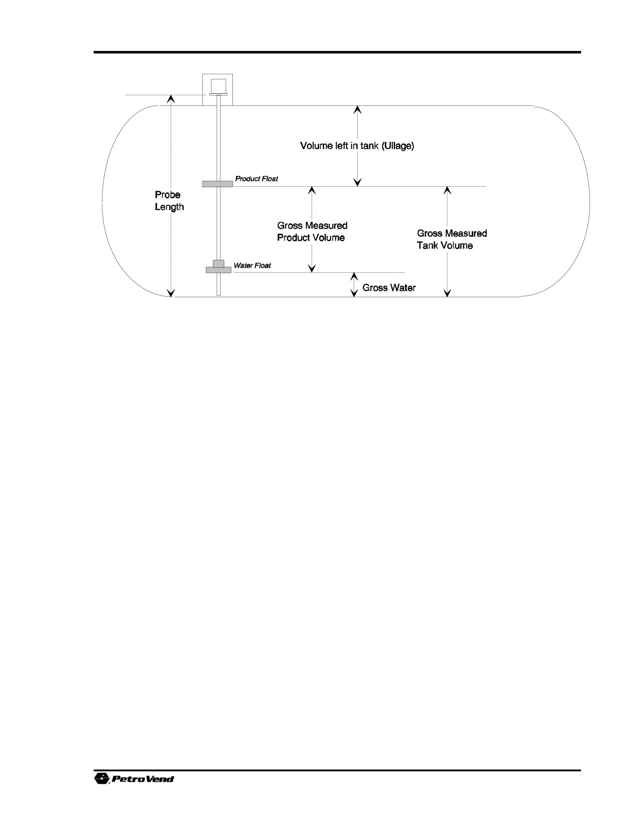
6.1.3 Report Terms
Use these definitions, and the illustration above, to better understand the data presented in the various
reports.
PRODUCT LEVEL
This is
t
the position of the indicator on the probe.
WATER LEVEL
This is the distance of the water float from the bottom of the tank.
AVERAGE PRODUCT TEMPERATURE
This is the average of the readings from the probe temperature sensors that are submersed in product (or
water). Any temperature sensors that are above the product level are ignored.
VOLUME LEFT IN TANK
The volume above product, or "ullage," is calculated by s
setup tank volume.
113
SiteSentinel
GROSS MEASURED TANK VOLUME
This volume is calculated from the position of the product float. This value includes water and product; it
is not corrected for temperature.
NET CORRECTED TANK VOLUME
The gross measured tank volume is calculated and corrected with measurements from the temperature sensors. This
value is the most accurate measure of a sale, delivery or inventory.
GROSS MEASURED PRODUCT VOLUME
This volum
corrected for temperature.
NET CORRECTED PRODUCT VOLUME
The gross measured tank volume is calculated. The water volume is calculated and subtracted from the gross
measured tank volume. The remaining product volume is then corrected with measurements from the
temperature sensors.
GROSS WATER
This is the volume of the water. This value is not corrected for temperature.
114
Current & Saved Event Reports
6.2 Controller Status Report
MAIN MENU L ‰ L Ì
SITE SENTINEL
OCT 25, 1994
8:36 AM
CONTROLLER STATUS
- EPROM VERSION
:
1.08B-USA-235
CHECKSUM
: xxxxxxxxx
STATUS
: OKAY
- SITE/SYSTEM STATE
: OPENED
- PRINTER TYPE
: INTERNAL
STATUS
: OKAY
- HISTORY/BUFFER SIZE
TOTAL RECORDS
:
1234
FREE RECORDS
:
1234
USED RECORDS
:
0
- BATTERY TEST RESULT
: P A S S E D
- LAST FOUR POWER FAILURE OCCURANCES
NOV
4,
1994
10:32 AM
NOV
8,
1994
2:54 PM
NOV
8,
1994
3:17 PM
NOV
8,
1994
11;55 PM
Enter
#, C/CANCEL, H/HELP or
0/Print:
EPROM Version: This is the software version and "nationality" that is installed in the controller.
EPROM checksum is the result of a test of the ICs that store the operating system. If Status is okay,
the operating system is functioning properly. If the checksum is not indicated as okay, contact your
service representative.
Site/System State can be either OPEN or CLOSED. When open, product withdrawn is defined by the
system as a sale. When closed, product withdrawn is defined as a theft. To change the operational state,
see Page 101.History/Buffer Size is the amount of memory available to store data. The total number of
records may vary slightly between software versions.
Battery Test Result. A "backup battery" protects the system data in case of a power failure. During
operation, this battery is tested automatically every day, just after midnight. In addition, the system tests
the battery after an initial powerup and after a power failure. The result of the most recent battery test
is displayed.
Last Four Power Failure Occurrences. The date and time of the last four power failures are listed.
115
SiteSentinel
6.3. Tank, Probe & Sensor Status Graphs Report
MAIN MENU L ‰ L Ó
SITE SENTINEL
NOV
8,
1994
8:36 AM
TANK, PROBE & SENSOR STATUS GRAPH MENU
1.MODULE
2.GRAPH TYPE:
PROBE LEVEL
3.CONTINUOUS, ONE MINUTE UPDATES
PSTNS: A B C D E F G H I J K L M N O P
+--------------------------------
TOP|
75|
|
50|
|
25|
|
BOTTOM
LEGEND: "."=NONE
"T"=TEST
"S"=STOP
ENTER
#, C/CANCEL, H/HELP OR
0/PRINT:
To graphically monitor the system's ongoing probe and sensor measurements, you can print and display
the Smart Module and I/O Module status graphs. For a complete description of the status graphs, see
Page 50.
6.3.1 Graph Type
Two graphs are available for each active smart module; an additional graph displays for each active I/O
Module. You may view either one from this menu. Press the [NO] or [N] key to toggle the options for
this feature. When the appropriate option displays, press [Enter].
The first Smart Module graph indicates the current level of each product float as a percentage of its tank
diameter (`PROBE LEVEL'). The second Smart Module graph shows the current gross product volume
for each tank as a percentage of its total volume (`TANK VOLUME').
Sensors are indicated with either a bar level showing the voltage measurement as a percentage of five
volts, text indicating a normal or alert status, or both. The status graph for the I/O modules indicates
whether each module position is currently "open," "closed," "energized," "not energized," or "removed
from operation."
6.3.2 Continuous, One Minute Updates
This feature lets you monitor the status of the Smart and I/O Modules. When the timed auto-logout
feature is enabled, data is updated every minute for a period of five minutes. The auto-logout feature may
be disabled to allow continuous viewing and updates. For more information about the timed auto-logout
feature see Page 37.
116
Current & Saved Event Reports
6.4 Tank Inventory Report
MAIN MENU L ‰ L Ô
An inventory report can be printed and displayed for each tank, showing the current values of the
following:
ë Gross measured product, water, and tank levels and volumes
ë Temperature-corrected product, water, and tank volumes
ë Amount of product needed to fill the tank completely ("ullage"), and to 90% capacity
ë Average product temperature.
Manifolded Tanks: An inventory report is generated for the group. The manifolded inventory report
sums the product and water volumes for a group, but does not contain level or 90% ullage information.
Tank Inventory Reports can also be selected directly from the MAIN MENU. When you generate it in
this way, you do not have to specify a tank range or position. The printed and displayed reports, though
slightly different in format, contain the same information.
When a level reading is not applicable to a type of measurement, it is noted as `NA'.
A tank or manifolded group must be configured in order for the system to generate its inventory report.
The terms used in this report are defined on Page 113.
Refer to Page 111 for setup information on the report output and range.
6.5 Sensor Levels Report
MAIN MENU L ‰ L ð
This report lists the values for all sensors. Refer to Page 111 for setup information on the report output
and range.
117
SiteSentinel
6.6 Warnings in Progress Report
MAIN MENU L ‰ L Ò
This report indicates all events (overflow, printer failure, sensor level high, etc.) that are currently in
progress (except power failure). If several events have been programmed to trigger an alarm, this report
can show which event is occurring.
Warnings can be printed in the sequence they occurred or grouped by category.
For the "screen" display, only one event can be viewed at a time.
The Warnings in Progress Report includes all events that are currently in progress.
For events that have ended (and are recorded in the event history buffer), there are four reports available;
see Page 44 for Event History information.
For event data to be recorded in the SiteSentinel history buffer, you must have at least one alarm method
programmed for activation at the event's start. Note that this condition must also be met for the data to
be included in any report. Refer to Page 88 for information on the alarm setup.
Refer to Page 111 for setup information on the report output and range.
118
Current & Saved Event Reports
6.7 Sensor, Probe, Input, & HW Failure Events Report
MAIN MENU L ‰ L Ú
This report indicates all events (overflow, printer failure, sensor level high, etc.) that have ended and are
stored in event history buffer.
Events can be printed in the sequence they occurred or grouped by categories. Note that for the "screen"
display, only one event can be viewed at a time. Refer to Page 72 for information on setting the
thresholds for tank and sensor events (overflow, low product, minimum theft, sale, and delivery).
For event data to be recorded in the SiteSentinel history buffer, you must have at least one alarm method
programmed for activation at the event's start. Note that this condition must also be met for the data to
be included in any report.
6.8 Sensor, Probe, & Input Events Menu
MAIN MENU L ‰ L Û
This report indicates all events - except hardware failure - that have ended and are stored in event history
buffer. These events include overflow, low product, high water, bad probe temperatures, thefts,
deliveries sales, timed leak tests, high and low sensor levels, and external input closures.
Events can be printed in the sequence they occurred or grouped by categories.
Note that for the "screen" display, only one event can be viewed at a time.Refer to Page 72 for
information on setting the thresholds for tank events (overflow, low product, minimum theft, sale, and
delivery).
For event data to be recorded in the SiteSentinel history buffer, you must have at least one alarm method
programmed for activation at the event's start. Note that this condition must also be met for the data to
be included in any report. Refer to Page 88 for information on the alarm setup.
Refer to Page 44 for information about the event history buffer. Refer to Page 111 for setup information
on the report output and range.
6.9 Hardware Failure Events Menu
MAIN MENU L ‰ L Ù
This report indicates all hardware failure events that have ended and are stored in event history buffer.
These events include: probe, Smart Module, Model II internal printer and power failures. Events can be
printed in the sequence they occurred or grouped by categories.
For event data to be recorded in the SiteSentinel history buffer, you must have at least one alarm method
programmed for activation at the event's start. Note that this condition must also be met for the data to
be included in any report. Refer to Page 111 for setup information on the report output and range.
119
SiteSentinel
6.10 Individual Events Menu
MAIN MENU L ‰ L ı
SITE SENTINEL
OCT
25,
1994
8:36 AM
INDIVIDUAL REPORTS MENU
1.OVERFLOW
2.LOW PRODUCT
3.HIGH WATER
4.BAD TEMPERATURES
5.THEFTS
6.DELIVERIES
7.SALES
8.TIMED LEAK TEST
9.HIGH SENSOR LEVELS
10.LOW SENSOR LEVELS
11.I/O MODULE INPUTS
12.INPUT
#1 CONTACT CLOSURES
13.INPUT
#2 CONTACT CLOSURES
14.PROBE FAILURES
15.MODULE FAILURES
16.PRINTER FAILURES
17.POWER FAILURES
Enter
#, C/CANCEL, H/HELP or
0/Print:
This menu lets you report on the 17 listed specific events stored in event history buffer.
Refer to Page 44 for information about the event history buffer.
Events can be printed in the sequence they occurred or grouped by categories (see Page 111 for report
output setup).
Manifolded Tanks. Thefts, sales, and deliveries can be reported both for each individual tank and for
the manifolded group. Level information is not included in group reports.Thresholds. Refer to Page 72
for information on setting the thresholds for tank events (overflow, low product, minimum theft, sale, and
delivery).
For events to be recorded in the history buffer, and for the data to be included in any report, you must
have at least one alarm programmed for activation at the event's start.
120
Current & Saved Event Reports
6.11 Saved Tank Inventories Report
MAIN MENU L ‰ L (11)
SAVED TANK INVENTORY
MODULE:
DESCRIPTION:
PRODUCT:
MAR 09, 1995
3:30 PM
TEMP HEIGHT
VOLUMES (GAL)
(F)
(IN)
MEASURED CORRECTED
______________________________________________
PRODUCT
NA
66.52
392.46
388.64
WATER
NA
28.65
69.22
68.48
TOTAL
74.0
92.16
461.66
457.18
ULLAGE
NA
907.84
9530.25
NA
This report shows inventories saved in system memory. Each position is checked in sequence.
121
SiteSentinel
6.12 I/O Module Status Report
MAIN MENU L ‰ L (12)
SITE SENTINEL
MAR
9,
1995
8:36 AM
I/O MODULE STATUS REPORT MENU
1.CONTINUOUS, FOUR SECOND UPDATES.
|MOD|
POSITIONS
|
|
|-INPUTS-|-------OUTPUTS----------|
|
#
| A B C D E F G H I J K L M N O P
|
+---+---------------------------------+
|
1
| O C O O E E E E E E E E E E E E
|
|
2
| NOT INSTALLED
|
|
3
| NOT INSTALLED
|
|
4
| NOT INSTALLED
|
|
5
| NOT INSTALLED
|
|
6
| NOT INSTALLED
|
|
7
| NOT INSTALLED
|
|
8
| NOT INSTALLED
|
LEGEND:"O"=OPENED
"N"=NOT ENERGIZED
"C"=CLOSED
"E"=ENERGIZED
"R"=REMOVED FROM OPERATION
This report shows the current operating condition of the optional I/O Module(s).
Press 1 for continuous (every four seconds) update.
122
Chapter 7 - Scheduled Commands & Reports
MAIN MENU L ð
SITE SENTINEL
OCT
24,
1994
8:36 AM
SCHEDULE COMMANDS & REPORTS MENU
SYSTEM COMMANDS:
1.OPEN/CLOSE SYSTEM
2.CLEAR HISTORY BUFFER
3.TIMED LEAK TESTS
4.SAVE TANK INVENTORY
REPORTS:
5.IN PROGRESS WARNING REPORT
6.SAVED EVENT REPORT
7.INVENTORY REPORT
8.DELIVERY REPORT
ENTER
#, C/CANCEL, H/HELP OR
0/PRINT:
The commands and reports listed in this menu can be scheduled to execute at select dates and times.
Frequency. You can specify events to occur as follows:
G Single occasion
G Daily
G Weekly
G Monthly
Each event can have up to 15 different frequencies.
SCHEDULED SYSTEM COMMANDS
The following system commands can be scheduled:
G Open/Close System (Page 125)
G Clear History Buffer (Page 126)
G Timed Leak Tests (Page 127)
G Save Tank Inventory (Page 128)
123
SiteSentinel
SCHEDULED REPORTS
The following reports can be scheduled (all are explained in one menu, on Page 129).
G In-Progress Warnings
G Saved Events
G Inventory
G Deliveries
EXAMPLE
A site could be programmed as follows:
Use OPEN/CLOSE scheduling:
Weekdays:
Open 7:00 AM, and close at 9:00 PM.
Weekends:
Open 6:00 AM, and close at 11:00 PM
Delivery reports can be saved every day after closing and inventory reports can be printed out at the end
of the week.
124
Scheduled Commands & Reports
7.1 Scheduled Open/Close System
MAIN MENU L Ê L Ï
SITE SENTINEL
OCT
24,
1994
8:36 AM
SYSTEM OPEN CLOSE SCHEDULE
FREQ DATE
TIME
STATE
----
------------
---------
------
1.1/DY MAR
2,
1993
7:00 AM
OPEN
2.1/DY MAR
2,
1993
9:00 PM
CLOSE
3.
4.
5.
6.
7.
8.
9.
10.
11.
12.
13.
14.
15.
PROCEDURE
1. Enter one of the following frequencies:
ONCE - only one time
1/DY - daily
1/WK - weekly (same day each week)
1/MO - monthly (same date each month)
To clear a scheduled item, enter `CLR' for its frequency.
2. Enter the date to first execute the command.
3. Enter the time to execute the command.
4. Enter either `OPEN' or `CLOSE' for the state.
125
SiteSentinel
7.2 Scheduled Clear History Buffer
MAIN MENU L Ê L Ì
SITE SENTINEL
OCT
24,
1994
8:36 AM
CLEAR HISTORY BUFFER
FREQ DATE
TIME
----
------------
---------
1.1/WK MAR
2,
1993
6:00 AM
2.1/WK MAR
6,
1993
6:00 AM
3.
4.
5.
6.
7.
8.
9.
10.
11.
12.
13.
14.
15.
PROCEDURE
1. Enter one of the following frequencies:
ONCE - only one time
1/DY - daily
1/WK - weekly (same day each week)
1/MO - monthly (same date each month)
To clear a scheduled item, enter `CLR' for its frequency.
2. Enter the date to first execute the command.
3. Enter the time to execute the command.
126
Scheduled Commands & Reports
7.3 Scheduled Timed Leak Test
MAIN MENU L Ê L Ó
SITE SENTINEL
OCT
24,
1994
8:36 AM
TIMED LEAK TESTS SCHEDULE
FREQ DATE
TIME
POSTN DUR
RANGE HRS
----
------------
---------
-----
---
1.1/WK MAR
8,
1993
7:00 AM
1A-1P
2
2.1/WK MAR
8,
1993
9:00 AM
2A-2P
2
3.1/WK MAR
8,
1993
11:00 AM
3A-3P
2
4.1/WK MAR
8,
1993
1 PM PM
4A-3P
2
5.1/WK MAR
8,
1993
3:00 PM
1A-1P
2
6.1/WK MAR
8,
1993
5:00 PM
2A-2P
2
7.1/WK MAR
8,
1993
7:00 PM
3A-3P
2
8.1/WK MAR
8,
1993
9:00 PM
4A-3P
2
9.
10.
11.
12.
13.
14.
15.
16.SAVE HOURLY INTERMEDIATE RESULTS? N
PROCEDURE
1. Enter one of the following frequencies:
ONCE - only one time
1/DY - daily
1/WK - weekly (same day each week)
1/MO - monthly (same date each month)
To clear a scheduled item, enter `CLR' for its frequency.
2. Enter a date and time to first execute the command.
Next, you are prompted for a range of modules and positions. The cursor moves to the beginning range
specifier (`1A') in the menu.
3. Enter a module and position. The cursor moves to the terminating range specifier; enter a module
and position. For example, to test tanks connected to module 1, positions A, B, C and D, you would
specify `1A-1D'.
4. Enter a duration for test. This entry must be a whole number; that is 1, 2, 3, etc. The MINIMUM
recommended duration for the timed leak test is two hours.
5. Specify if you want to save intermediate hourly data from the test. Enter `Y' (for yes) or `N' (for no)
as appropriate.
127
SiteSentinel
7.4 Scheduled Save Tank Inventory
MAIN MENU L Ê L Ô
SITE SENTINEL
OCT
24,
1994
8:36 AM
SAVE TANK INVENTORIES
FREQ DATE
TIME
RANGE
----
------------
---------
-----
1.1/DY MAR
2,
1993
6:30 AM
1A-1P
2.1/DY MAR
2,
1993
9:00 PM
2A-2P
3.
4.
5.
6.
7.
8.
9.
10.
11.
12.
13.
14.
15.
PROCEDURE
1. Enter one of the following frequencies:
ONCE - only one time
1/DY - daily
1/WK - weekly (same day each week)
1/MO - monthly (same date each month)
To clear a scheduled item, enter `CLR' for its frequency.
2. Enter the date to first execute the command.
3. Enter the time to execute the command.
4. Enter a continuous range of module positions for inventory.
For example, to inventory tanks connected to module 1, positions A, B, C and D, you would specify
`1A-1D'.
128
Scheduled Commands & Reports
7.5 Scheduled Reports
MAIN MENU L Ê L ð, Ò, Ú, or Û
SITE SENTINEL
OCT
25,
1994
8:36 AM
{
}
REPORT SCHEDULE
FREQ DATE
TIME
----
------------
---------
1.1/DY OCT
24,
1994
7:30 AM
2.1/DY OCT
24,
1994
8:00 PM
3.
4.
5.
6.
7.
8.
9.
10.
11.
12.
13.
14.
15.
The above menu is generic, which is why the Menu Path shows you can press 5, 6, 7 or 8 after accessing
the Scheduled Commands/Reports submenu:
1. From the Scheduled Reports menu:
Press ð to schedule In Progress Warnings
Press Ò to schedule Saved Events Reports
Press Ú to schedule Inventory Reports
Press Û to schedule Delivery Reports
2. Enter one of the following frequencies:
ONCE - only one time
1/DY - daily
1/WK - weekly (same day each week)
1/MO - monthly (same date each month)
To clear a scheduled item, enter `CLR' for its frequency.
3. Enter the date and time to first print the report.
129
SiteSentinel
Notes:
130
Chapter 8 - Quick Sale and Delivery Reports
8.1 Quick Sale Report
MAIN MENU L Û
This report can only be PRINTED, so you must have a printer attached to use this feature.
A Quick Sales Report shows sales in progress, or recently completed. Use this function to generate a
"quick ticket".
This report is available for a tank only while product is withdrawn (and for several minutes thereafter,
depending on the size of the sale). If the report is no longer available, you can generate an End of Event
Report.
The report is selected directly from the MAIN MENU. You can be in either normal or privileged mode.
With a quick report you do not have to specify a tank range or position. The SiteSentinel automatically
checks all its probe positions and prints a report for each one currently active. Because of product
turbulence, the values in a quick report may not be exactly the same as those in the corresponding
Individual Event Report.
Quick Reports do not have corresponding computer formats.
8.2 Quick Delivery Report
MAIN MENU L Ù
This report can only be PRINTED, so you must have a printer attached to use this feature.
A Quick Delivery Report shows deliveries in progress, or recently completed. Use this function to
generate a "quick ticket".
This report is available for a tank only while product is added (and for several minutes thereafter,
depending on the size of the delivery). If the report is no longer available, you can generate an End of
Event Report.
The report is selected directly from the MAIN MENU. You can be in either normal or privileged
mode.With a quick report you do not have to specify a tank range or position. The SiteSentinel
automatically checks all its probe positions and prints a report for each one currently active.
Because of product turbulence, the values in a quick report may not be exactly the same as those in the
corresponding Individual Event Report.
Quick Reports do not have corresponding computer formats.
131
SiteSentinel
Notes:
132
Appendix A - System Setup Worksheet
SECURITY SETUP
Privileged Password
Restricted Mode
Enabled Disabled
Restricted Password
Timed Auto Logout
Enabled Disabled
TIME/DATE SETUP
Date Format
Time Format
Format
Format
Order (long)
Before Noon Suffix
Order (short)
After Noon Suffix
Separator (short)
Separator
Leading Character
Leading Character
PRINTER SETUP
Printer Type
Top of Page Header
(four lines of up to 40
characters each)
Leading Page Form
Enabled
Disabled
Feed
Trailing Page Form
Enabled
Disabled
Feed
133