Physics For Scientists And Engineers 6E - part 247
 

  Index      Production     Physics For Scientists And Engineers 6E


Search            


Content   ..  245  246  247  248   ..


Physics For Scientists And Engineers 6E - part 247


SECTION 31.5 •  Generators and Motors

985

in reverse. Instead of generating a current by rotating a coil, a current is supplied to
the coil by a battery, and the torque acting on the current-carrying coil causes it to
rotate.

Useful mechanical work can be done by attaching the rotating coil to some exter-

nal device. However, as the coil rotates in a magnetic field, the changing magnetic flux
induces an emf in the coil; this induced emf always acts to reduce the current in the
coil. If this were not the case, Lenz’s law would be violated. The back emf increases in
magnitude as the rotational speed of the coil increases. (The phrase back emf is used to
indicate an emf that tends to reduce the supplied current.) Because the voltage avail-
able to supply current equals the difference between the supply voltage and the back
emf, the current in the rotating coil is limited by the back emf.

When a motor is turned on, there is initially no back emf; thus, the current is very

large because it is limited only by the resistance of the coil. As the coil begins to rotate,
the  induced  back  emf  opposes  the  applied  voltage,  and  the  current  in  the  coil  is
reduced. If the mechanical load increases, the motor slows down; this causes the back
emf to decrease. This reduction in the back emf increases the current in the coil and
therefore also increases the power needed from the external voltage source. For this
reason, the power requirements for starting a motor and for running it are greater for
heavy loads than for light ones. If the motor is allowed to run under no mechanical
load,  the  back  emf  reduces  the  current  to  a  value  just  large  enough  to  overcome
energy losses due to internal energy and friction. If a very heavy load jams the motor so
that it cannot rotate, the lack of a back emf can lead to dangerously high current in
the motor’s wire. This is a dangerous situation, and is explored in the What If? section
of Example 31.10.

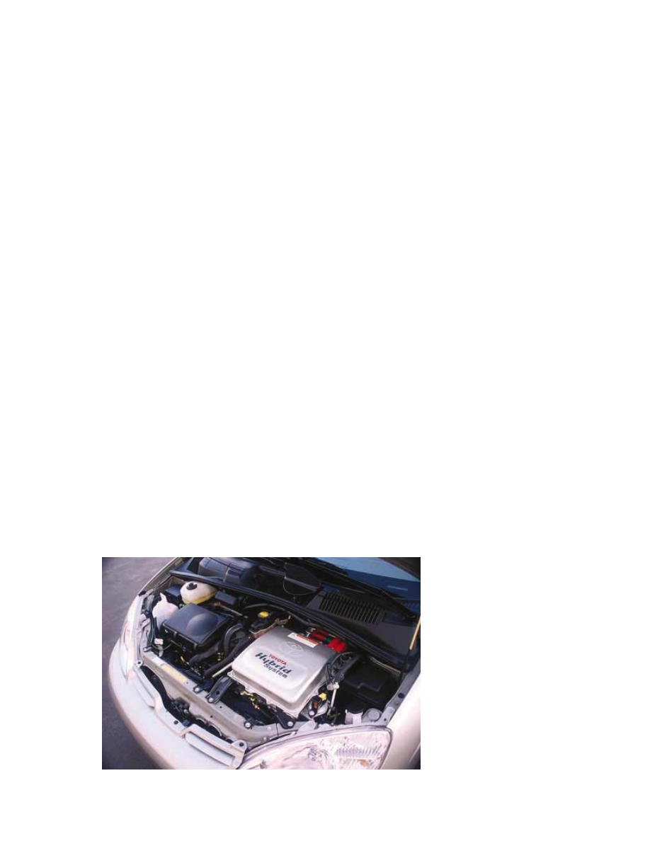
A  current  application  of  motors  in  automobiles  is  seen  in  the  development  of

hybrid drive systems. In these automobiles, a gasoline engine and an electric motor are
combined to increase the fuel economy of the vehicle and reduce its emissions. Figure
31.24  shows  the  engine  compartment  of  the  Toyota  Prius,  which  is  one  of  a  small
number  of  hybrids  available  in  the  United  States.  In  this  automobile,  power  to  the
wheels  can  come  from  either  the  gasoline  engine  or  the  electric  motor.  In  normal
driving, the electric motor accelerates the vehicle from rest until it is moving at a speed
of  about  15 mi/h  (24 km/h).  During  this  acceleration  period,  the  engine  is  not 
running, so that gasoline is not used and there is no emission. When a hybrid vehicle
brakes, the motor acts as a generator and returns some of the kinetic energy of the ve-
hicle  back  to  the  battery  as  stored  energy.  In  a  normal  vehicle,  this  kinetic  energy  is
simply lost as it is transformed to internal energy in the brakes and roadway.

Figure 31.24 The engine compartment of the Toyota Prius, a hybrid vehicle.

Photo by Brent Romans/

www

.Edmunds.com

31.6 Eddy Currents

As  we  have  seen,  an  emf  and  a  current  are  induced  in  a  circuit  by  a  changing
magnetic  flux.  In  the  same  manner,  circulating  currents  called 

eddy  currents are

induced in bulk pieces of metal moving through a magnetic field. This can easily be
demonstrated by allowing a flat copper or aluminum plate attached at the end of a
rigid bar to swing back and forth through a magnetic field (Fig. 31.25). As the plate
enters the field, the changing magnetic flux induces an emf in the plate, which in
turn  causes  the  free  electrons  in  the  plate  to  move,  producing  the  swirling  eddy
currents.  According  to  Lenz’s  law,  the  direction  of  the  eddy  currents  is  such  that
they create magnetic fields that oppose the change that causes the currents. For this
reason,  the  eddy  currents  must  produce  effective  magnetic  poles  on  the  plate,
which  are  repelled  by  the  poles  of  the  magnet;  this  gives  rise  to  a  repulsive  force
that  opposes  the  motion  of  the  plate.  (If  the  opposite  were  true,  the  plate  would
accelerate and its energy would increase after each swing, in violation of the law of
conservation of energy.)

As  indicated  in  Figure  31.26a,  with 

B directed  into  the  page,  the  induced  eddy

current is counterclockwise as the swinging plate enters the field at position 1. This is
because the flux due to the external magnetic field into the page through the plate is
increasing,  and  hence  by  Lenz’s  law  the  induced  current  must  provide  its  own
magnetic  field  out  of  the  page.  The  opposite  is  true  as  the  plate  leaves  the  field  at
position  2,  where  the  current  is  clockwise.  Because  the  induced  eddy  current  always
produces a magnetic retarding force 

F

B

when the plate enters or leaves the field, the

swinging plate eventually comes to rest.

If  slots  are  cut  in  the  plate,  as  shown  in  Figure  31.26b,  the  eddy  currents  and

the corresponding  retarding  force  are  greatly  reduced.  We  can  understand  this

986

CHAPTE R 31 •  Faraday’s Law

Example 31.10 The Induced Current in a Motor

Assume that a motor in which the coil has a total resistance
of 10 ( is supplied by a voltage of 120 V. When the motor is
running  at  its  maximum  speed,  the  back  emf  is  70 V.  Find
the current in the coil

(A)

when the motor is turned on and

(B)

when it has reached maximum speed.

Solution (A) When the motor is first turned on, the back
emf  is  zero  (because  the  coil  is  motionless).  Thus,  the
current in the coil is a maximum and equal to

(B) At the maximum speed, the back emf has its maximum
value. Thus, the effective supply voltage is that of the exter-
nal  source  minus  the  back  emf.  Hence,  the  current  is
reduced to

What  If?

Suppose that this motor is in a circular saw. You

are  operating  the  saw  and  the  blade  becomes  jammed  in  a

5.0 A

"

$

%

$

back

R

"

120 V % 70 V

10 (

"

50 V

10 (

"

12 A

"

$

R

"

120 V

10 (

"

piece  of  wood  so  that  the  motor  cannot  turn.  By  what
percentage does the power input to the motor increase when
it is jammed?

Answer You  may  have  everyday  experiences  with  motors
becoming  warm  when  they  are  prevented  from  turning.
This is due to the increased power input to the motor. The
higher  rate  of  energy  transfer  results  in  an  increase  in  the
internal energy of the coil, an undesirable effect. When the
motor is jammed, the current is that given in part (A). Let
us  set  up  the  ratio  of  power  input  to  the  motor  when
jammed to that when it is not jammed:

where  the  subscripts  (A)  and  (B)  refer  to  the  currents  in
parts (A) and (B) of the example. Substituting these values,

This represents a 476% increase in the input power! Such a
high power input can cause the coil to become so hot that it
is damaged.

"

jammed

"

not jammed

"

(12 A)

2

(5.0 A)

2

"

5.76

"

jammed

"

not jammed

"

I

(A)

2

R

I

(B)

2

R

"

I

(A)

2

I

(B)

2

v

Pivot

S

N

Figure 31.25 Formation of eddy

currents in a conducting plate

moving through a magnetic field.

As the plate enters or leaves the

field, the changing magnetic flux

induces an emf, which causes eddy

currents in the plate.

by realizing  that  the  cuts  in  the  plate  prevent  the  formation  of  any  large  current
loops.

The  braking  systems  on  many  subway  and  rapid-transit  cars  make  use  of  electro-

magnetic induction and eddy currents. An electromagnet attached to the train is posi-
tioned  near  the  steel  rails.  (An  electromagnet  is  essentially  a  solenoid  with  an  iron
core.) The braking action occurs when a large current is passed through the electro-
magnet. The relative motion of the magnet and rails induces eddy currents in the rails,
and the direction of these currents produces a drag force on the moving train. Because
the eddy currents decrease steadily in magnitude as the train slows down, the braking
effect is quite smooth. As a safety measure, some power tools use eddy currents to stop
rapidly spinning blades once the device is turned off.

Eddy currents are often undesirable because they represent a transformation of

mechanical energy to internal energy. To reduce this energy loss, conducting parts
are often laminated—that is, they are built up in thin layers separated by a noncon-
ducting material such as lacquer or a metal oxide. This layered structure increases
the resistance of eddy current paths and effectively confines the currents to individ-
ual  layers.  Such  a  laminated  structure  is  used  in  transformer  cores  (see  Section
33.8) and motors to minimize eddy currents and thereby increase the efficiency of
these devices.

SECTION 31.6 •  Eddy Currents

987

Active Figure 31.26 (a) As the conducting plate enters the field (position 1), the eddy

currents are counterclockwise. As the plate leaves the field (position 2), the currents

are clockwise. In either case, the force on the plate is opposite the velocity, and

eventually the plate comes to rest. (b) When slots are cut in the conducting plate, the

eddy currents are reduced and the plate swings more freely through the magnetic field.

F

B

Pivot

×

×

× ×

×

×

×

×

×

×

×

1

2

B

in

v

v

F

B

(a)

(b)

Choose to let a solid or a

slotted plate swing through the

magnetic field and observe the

effect at the Active Figures link

at http://www.pse6.com.

Quick Quiz 31.11

In equal-arm balances from the early twentieth century

(Fig. 31.27), it is sometimes observed that an aluminum sheet hangs from one of the
arms  and  passes  between  the  poles  of  a  magnet.  This  causes  the  oscillations  of  the
equal-arm balance to decay rapidly. In the absence of such magnetic braking, the oscil-
lation might continue for a very long time, so that the experimenter would have to wait
to take a reading. The oscillations decay because (a) the aluminum sheet is attracted to
the magnet; (b) currents in the aluminum sheet set up a magnetic field that opposes
the oscillations; (c) aluminum is paramagnetic.

31.7 Maxwell’s Equations

We conclude this chapter by presenting four equations that are regarded as the basis of
all  electrical  and  magnetic  phenomena.  These  equations,  developed  by  James  Clerk
Maxwell,  are  as  fundamental  to  electromagnetic  phenomena  as  Newton’s  laws  are  to
mechanical  phenomena.  In  fact,  the  theory  that  Maxwell  developed  was  more  far-
reaching  than  even  he  imagined  because  it  turned  out  to  be  in  agreement  with  the
special theory of relativity, as Einstein showed in 1905.

Maxwell’s equations represent the laws of electricity and magnetism that we have

already discussed, but they have additional important consequences. In Chapter 34 we
shall  show  that  these  equations  predict  the  existence  of  electromagnetic  waves
(traveling  patterns  of  electric  and  magnetic  fields),  which  travel  with  a  speed

the speed of light. Furthermore, the theory shows that

such waves are radiated by accelerating charges.

For simplicity, we present 

Maxwell’s equations as applied to free space, that is, in

the absence of any dielectric or magnetic material. The four equations are

(31.12)

'

S


E&dA "

q

1

0

" 1/

√/

0

1

0

"

3.00 + 10

8

 m/s,

988

CHAPTE R 31 •  Faraday’s Law

Figure 31.27 (Quick Quiz 31.11) In an old-fashioned equal-arm balance, an

aluminum sheet hangs between the poles of a magnet.

John W

. Jewett, Jr

.

Gauss’s law


Content   ..  245  246  247  248   ..