Physics For Scientists And Engineers 6E - part 109
 

  Index      Production     Physics For Scientists And Engineers 6E


Search            


Content   ..  107  108  109  110   ..


Physics For Scientists And Engineers 6E - part 109


14.6 Bernoulli’s Equation

You  have  probably  had  the  experience  of  driving  on  a  highway  and  having  a  large
truck pass you at high speed. In this situation, you may have had the frightening feel-
ing that your car was being pulled in toward the truck as it passed. We will investigate
the origin of this effect in this section.

As a fluid moves through a region where its speed and/or elevation above the Earth’s

surface changes, the pressure in the fluid varies with these changes. The relationship be-
tween fluid speed, pressure, and elevation was first derived in 1738 by the Swiss physicist
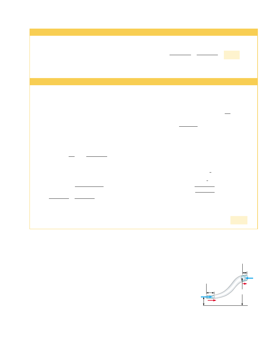
Daniel Bernoulli. Consider the flow of a segment of an ideal fluid through a nonuniform
pipe in a time interval 't, as illustrated in Figure 14.19. At the beginning of the time in-
terval, the segment of fluid consists of the blue shaded portion (portion 1) at the left and
the unshaded portion. During the time interval, the left end of the segment moves to the
right by a distance 'x

1

, which is the length of the blue shaded portion at the left. Mean-

while, the right end of the segment moves to the right through a distance 'x

2

, which is

the  length  of  the  blue  shaded  portion  (portion  2)  at  the  upper  right  of  Figure  14.19.

S E C T I O N   1 4 . 6 •  Bernoulli’s Equation

433

Example 14.7 Niagara Falls

The flow rate of 5 525 m

3

/s is equal to Av. This gives

Note that we have kept only one significant figure because
our value for the depth has only one significant figure.

4 m/s

!

5 525 m

3

/s

A

!

5 525 m

3

/s

1 340 m

2

!

Each  second,  5  525 m

3

of  water  flows  over  the  670-m-wide

cliff of the Horseshoe Falls portion of Niagara Falls. The wa-
ter is approximately 2 m deep as it reaches the cliff. What is
its speed at that instant?

Solution The cross-sectional area of the water as it reaches
the  edge  of  the  cliff  is  ! (670 m)(2 m) ! 1 340 m

2

.

Example 14.8 Watering a Garden

component  of  the  water  projected  from  the  hose,  and  the
subscript  recognizes  that  the  initial  velocity  vector  of  the
projected water is in the horizontal direction.

We now shift our thinking away from fluids and to projectile
motion because the water is in free fall once it exits the noz-
zle. A particle of the water falls through a vertical distance of
1.00 m starting from rest, and lands on the ground at a time
that we find from Equation 2.12:

In  the  horizontal  direction,  we  apply  Equation  2.12  with
a

x

!

0 to a particle of water to find the horizontal distance:

4.52 m

x

f

!

x

i

%

v

xi

! 0 % (10.0 m/s)(0.452 s) !

 !

2(1.00 m)

9.80 m/s

2

!

0.452 s

&

1.00 m ! 0 % 0 &

1

2

(9.80 m/s

2

)t

2

y

f

!

y

i

%

v

yi

&

1

2

gt

2

 ! 10.0 m/s

v

xi

!

4.91 cm

2

0.500 cm

2


(1.02 m/s)

A

1

v

1

!

A

2

v


2

!

A

2

v

xi

  9:   v

xi

!

A

1

A

2


 v

1

A  water  hose  2.50 cm  in  diameter  is  used  by  a  gardener
to fill  a  30.0-L  bucket.  The  gardener  notes  that  it  takes
1.00 min  to  fill  the  bucket.  A  nozzle  with  an  opening  of
cross-sectional area 0.500 cm

2

is then attached to the hose.

The  nozzle  is  held  so  that  water  is  projected  horizontally
from a point 1.00 m above the ground. Over what horizon-
tal distance can the water be projected?

Solution We identify point 1 within the hose and point 2 at
the  exit  of  the  nozzle.  We  first  find  the  speed  of  the  water
in the  hose  from  the  bucket-filling  information.  The  cross-
sectional area of the hose is

According to the data given, the volume flow rate is equal to
30.0 L/min:

Now  we  use  the  continuity  equation  for  fluids  to  find  the
speed  v

2

!

v

xi

with  which  the  water  exits  the  nozzle.  The

subscript  anticipates  that  this  will  be  the  initial velocity

 v

1

!

500 cm

3

/s

A

1

!

500 cm

3

/s

4.91 cm

2

!

102 cm/s ! 1.02 m/s

A

1

v

1

!

30.0 L/min !

30.0 " 10

3

 cm

3

60.0 s

!

500 cm

3

/s

A

1

!

#

r

2

!

#


d

2

4

!

#


"

(2.50 cm)

2

4

#

!

4.91 cm

2

x

1

x

2

v

2

y

2

y

1

P

1

A

1

i

v

1

P

2

A

2

i

Point 2

Point 1

ˆ

ˆ

Figure 14.19 A fluid in laminar

flow through a constricted pipe.

The volume of the shaded portion

on the left is equal to the volume of

the shaded portion on the right.

Thus, at the end of the time interval, the segment of fluid consists of the unshaded por-
tion and the blue shaded portion at the upper right.

Now consider forces exerted on this segment by fluid to the left and the right of the

segment. The force exerted by the fluid on the left end has a magnitude P

1

A

1

. The work

done by this force on the segment in a time interval 'is W

1

!

F

1

'

x

1

!

P

1

A

1

'

x

1

!

P

1

V,

where is the volume of portion 1. In a similar manner, the work done by the fluid to
the right of the segment in the same time interval 'is W

2

! &

P

2

A

2

'

x

2

! &

P

2

V. (The

volume of portion 1 equals the volume of portion 2.) This work is negative because the
force on the segment of fluid is to the left and the displacement is to the right. Thus,
the net work done on the segment by these forces in the time interval 'is

Part of this work goes into changing the kinetic energy of the segment of  fluid, and
part  goes  into  changing  the  gravitational  potential  energy  of  the  segment–Earth  sys-
tem. Because we are assuming streamline flow, the kinetic energy of the unshaded por-
tion of the segment in Figure 14.19 is unchanged during the time interval. The only
change is as follows: before the time interval we have portion 1 traveling at v

1

, whereas

after the time interval, we have portion 2 traveling at v

2

. Thus, the change in the ki-

netic energy of the segment of fluid is

where  is  the  mass  of  both  portion  1  and  portion  2.  (Because  the  volumes  of  both
portions are the same, they also have the same mass.)

Considering  the  gravitational  potential  energy  of  the  segment–Earth  system,  once

again there is no change during the time interval for the unshaded portion of the fluid.
The net change is that the mass of the fluid in portion 1 has effectively been moved to the
location of portion 2. Consequently, the change in gravitational potential energy is

The  total  work  done  on  the  system  by  the  fluid  outside  the  segment  is  equal  to  the
change  in  mechanical  energy  of  the  system:  ! '% 'U.  Substituting  for  each  of
these terms, we obtain

If we divide each term by the portion volume and recall that $ ! m/V, this expres-
sion reduces to

Rearranging terms, we obtain

(14.8)

This is 

Bernoulli’s equation as applied to an ideal fluid. It is often expressed as

(14.9)

This expression shows that the pressure of a fluid decreases as the speed of the fluid in-
creases.  In  addition,  the  pressure  decreases  as  the  elevation  increases.  This  explains
why water pressure from faucets on the upper floors of a tall building is weak unless
measures are taken to provide higher pressure for these upper floors.

When the fluid is at rest, v

1

!

v

2

!

0 and Equation 14.8 becomes

This is in agreement with Equation 14.4.

While Equation 14.9 was derived for an incompressible fluid, the general behavior

of  pressure  with  speed  is  true  even  for  gases—as  the  speed  increases,  the  pressure

P

1

&

P

2

!

$

g(y

2

&

y

1

) ! $gh

%

1

2

$

v

2

%

$

g y ! constant

P

1

%

1

2

$

v

2

1

%

$

gy

1

!

P

2

%

1

2

$

v

2

2

%

$

gy

2

P

1

&

P

2

!

1

2

$

v

2

2

&

1

2

$

v

1

2

%

$

gy

2

&

$

gy

1

(P

1

&

P

2

)!

1

2

mv

2

2

&

1

2

mv

2

1

%

mgy

2

&

mgy

1

'

mgy

2

&

mg y

1

'

!

1

2

mv

2

2

&

1

2

mv

1

2

! (P

1

&

P

2

)V

434

C H A P T E R   1 4 •  Fluid Mechanics

Bernoulli’s equation

Daniel Bernoulli

Swiss physicist 
(1700–1782)

Daniel Bernoulli made

important discoveries in fluid

dynamics. Born into a family of

mathematicians, he was the only

member of the family to make a

mark in physics.

Bernoulli’s most famous work,

Hydrodynamica, was published

in 1738; it is both a theoretical

and a practical study of

equilibrium, pressure, and speed

in fluids. He showed that as the

speed of a fluid increases, its

pressure decreases. Referred to

as “Bernoulli’s principle,” his

work is used to produce a partial

vacuum in chemical laboratories

by connecting a vessel to a tube

through which water is running

rapidly.

In Hydrodynamica, Bernoulli

also attempted the first

explanation of the behavior of

gases with changing pressure

and temperature; this was the

beginning of the kinetic theory of

gases, a topic we study in

Chapter 21. (Corbis–Bettmann)

S E C T I O N   1 4 . 6 •  Bernoulli’s Equation

435

Quick  Quiz  14.9

You  observe  two  helium  balloons  floating  next  to  each

other at the ends of strings secured to a table. The facing surfaces of the balloons are
separated  by  1–2 cm.  You  blow  through  the  small  space  between  the  balloons.  What
happens to the balloons? (a) They move toward each other. (b) They move away from
each other. (c) They are unaffected.

Example 14.9 The Venturi Tube

Solution Because the pipe is horizontal, y

1

!

y

2

, and apply-

ing Equation 14.8 to points 1 and 2 gives

From the equation of continuity, A

1

v

1

!

A

2

v

2

, we find that

Substituting this expression into Equation (1) gives

We can use this result and the continuity equation to obtain
an expression for  v

1

. Because A

2

(

A

1

, Equation (2) shows

us that v

2

)

v

1

. This result, together with Equation (1), in-

dicates  that  P

1

)

P

2

.  In  other  words,  the  pressure  is  re-

duced in the constricted part of the pipe.

A

1

2(P

1

&

P

2

)

$

(A

1

2

&

A

2

2

)

v

2

!

P

1

%

1

2

$

"

A

2

A

1

#

2

v

2

2

!

P

2

%

1

2

$

v

2

2

(2)


v

1

!

A

2

A

1

v

2

(1)


P

1

%

1

2

$

v

2

1

!

P

2

%

1

2

$

v

2

2

The horizontal constricted pipe illustrated in Figure 14.20,
known  as  a  Venturi  tube,  can  be  used  to  measure  the  flow
speed of an incompressible fluid. Determine the flow speed
at point 2 if the pressure difference P

1

&

P

is known.

P

1

P

2

A

2

A

1

!

(a)

v

1

v

2

"

(b)

Figure 14.20 (Example 14.9) (a) Pressure P

1

is greater than

pressure P

2

because v

1

(

v

2

. This device can be used to mea-

sure the speed of fluid flow. (b) A Venturi tube, located at the

top of the photograph. The higher level of fluid in the middle

column shows that the pressure at the top of the column, which

is in the constricted region of the Venturi tube, is lower.

Courtesy of Central Scientific Company

Example 14.10 Torricelli’s Law

An enclosed tank containing a liquid of density $ has a hole
in  its  side  at  a  distance  y

1

from  the  tank’s  bottom  (Fig.

14.21). The hole is open to the atmosphere, and its diame-
ter is much smaller than the diameter of the tank. The air
above  the  liquid  is  maintained  at  a  pressure  P.  Determine
the speed of the liquid as it leaves the hole when the liquid’s
level is a distance above the hole.

Solution Because  A

2

))

A

1

,  the  liquid  is  approximately 

at  rest  at  the  top  of  the  tank,  where  the  pressure  is  P.
Applying  Bernoulli’s  equation  to  points  1  and  2  and  not-
ing that at the hole P

1

is equal to atmospheric pressure P

0

,

we find that

P

0

%

1

2

$

v

1

2

%

$

gy

1

!

% $gy

2

decreases. This Bernoulli effect explains the experience with the truck on the highway at
the  opening  of  this  section.  As  air  passes  between  you  and  the  truck,  it  must  pass
through a relatively narrow channel. According to the continuity equation, the speed
of the air is higher. According to the Bernoulli effect, this higher speed air exerts less
pressure on your car than the slower moving air on the other side of your car. Thus,
there is a net force pushing you toward the truck!

A

2

A

1

v


1

P

0

h

P

y

2

y

1

"

!

Figure 14.21 (Example 14.10) A liquid leaves a hole in a tank

at speed v

1

But y

2

&

y

1

!

h; thus, this expression reduces to

v

1

!

2(P

0

)

$

%

2gh

Interactive

14.7 Other Applications of Fluid Dynamics

Consider the streamlines that flow around an airplane wing as shown in Figure 14.22. Let
us assume that the airstream approaches the wing horizontally from the right with a ve-
locity 

v

1

. The tilt of the wing causes the airstream to be deflected downward with a veloc-

ity 

v

2

. Because the airstream is deflected by the wing, the wing must exert a force on the

airstream. According to Newton’s third law, the airstream exerts a force 

F on the wing

that is equal in magnitude and opposite in direction. This force has a vertical component
called the 

lift (or aerodynamic lift) and a horizontal component called drag. The lift de-

pends on several factors, such as the speed of the airplane, the area of the wing, its curva-
ture, and the angle between the wing and the horizontal. The curvature of the wing sur-
faces causes the pressure above the wing to be lower than that below the wing, due to the
Bernoulli effect. This assists with the lift on the wing. As the angle between the wing and
the horizontal increases, turbulent flow can set in above the wing to reduce the lift.

In general, an object moving through a fluid experiences lift as the result of any ef-

fect that causes the fluid to change its direction as it flows past the object. Some factors
that influence lift are the shape of the object, its orientation with respect to the fluid
flow, any spinning motion it might have, and the texture of its surface. For example, a
golf ball struck with a club is given a rapid backspin due to the slant of the club. The
dimples on the ball increase the friction force between the ball and the air so that air
adheres to the ball’s surface. This effect is most pronounced on the top half of the ball,
where the ball’s surface is moving in the same direction as the air flow. Figure 14.23
shows air adhering to the ball and being deflected downward as a result. Because the
ball pushes the air down, the air must push up on the ball. Without the dimples, the
friction force is lower, and the golf ball does not travel as far. It may seem counterintu-
itive to increase the range by increasing the friction force, but the lift gained by spin-
ning the ball more than compensates for the loss of range due to the effect of friction

436

C H A P T E R   1 4 •  Fluid Mechanics

F

Drag

Lift

Figure 14.22 Streamline flow

around a moving airplane wing.

The air approaching from the right

is deflected downward by the wing.

By Newton’s third law, this must co-

incide with an upward force on the

wing from the air—lift. Because of

air resistance, there is also a force

opposite the velocity of the wing—

drag.

When  is  much  greater  than  P

0

(so  that  the  term  2gh

can  be  neglected),  the  exit  speed  of  the  water  is  mainly
a function of P. If the tank is open to the atmosphere, then
P

0

and 

In  other  words,  for  an  open  tank,

the speed of liquid coming out through a hole a distance h
below  the  surface  is  equal  to  that  acquired  by  an  object
falling  freely  through  a  vertical  distance  h.  This  phenome-
non is known as 

Torricelli’s law.

What  If?

What  if  the  position  of  the  hole  in  Figure  14.21

could be adjusted vertically? If the tank is open to the atmos-
phere and sitting on a table, what position of the hole would
cause the water to land on the table at the farthest distance
from the tank?

Answer We  model  a  parcel  of  water  exiting  the  hole  as  a
projectile.  We  find  the  time  at  which  the  parcel  strikes  the
table from a hole at an arbitrary position:

!

2y

1

g

0 ! y

1

%

0 &

1

2

gt

2

y

f

!

y

i

%

v

yi

&

1

2

gt

2

v

1

!

2gh .

Thus,  the  horizontal  position  of  the  parcel  at  the  time  it
strikes the table is

Now we maximize the horizontal position by taking the de-
rivative of x

f

with respect to y

1

(because y

1

, the height of the

hole,  is  the  variable  that  can  be  adjusted)  and  setting  it
equal to zero:

This is satisfied if

Thus, the hole should be halfway between the bottom of the
tank  and  the  upper  surface  of  the  water  to  maximize  the
horizontal  distance.  Below  this  location,  the  water  is  pro-
jected at a higher speed, but falls for a short time interval,
reducing the horizontal range. Above this point, the water is
in the air for a longer time interval, but is projected with a
smaller horizontal speed.

y

1

!

1

2

y

2

dx

f

dy

1

!

1

2

(2)(y

2

y

1

&

y

1

2

)

&

1/2

(y

2

&

2y

1

) ! 0

 ! 2

(y

2

y

1

&

y

1

2

)

x

f

!

x

i

%

v

xi

! 0 %

2g(y

2

&

y

1

2y

1

g

At the Interactive Worked Example link at http://www.pse6.com, you can move the hole vertically to see where the water lands.


Content   ..  107  108  109  110   ..