Physics For Scientists And Engineers 6E - part 94
S E C T I O N 1 2 . 4 • Elastic Properties of Solids
373
12.4 Elastic Properties of Solids
Except for our discussion about springs in earlier chapters, we have assumed that ob-
jects remain rigid when external forces act on them. In reality, all objects are de-
formable. That is, it is possible to change the shape or the size (or both) of an object
by applying external forces. As these changes take place, however, internal forces in
the object resist the deformation.
We shall discuss the deformation of solids in terms of the concepts of stress and
strain.
Stress is a quantity that is proportional to the force causing a deformation;
more specifically, stress is the external force acting on an object per unit cross-sec-
tional area. The result of a stress is
strain, which is a measure of the degree of defor-
mation. It is found that, for sufficiently small stresses,
strain is proportional to
stress; the constant of proportionality depends on the material being deformed and
on the nature of the deformation. We call this proportionality constant the
elastic
modulus. The elastic modulus is therefore defined as the ratio of the stress to the re-
sulting strain:
(12.5)
The elastic modulus in general relates what is done to a solid object (a force is ap-
plied) to how that object responds (it deforms to some extent).
We consider three types of deformation and define an elastic modulus for each:
Elastic modulus
$
stress
strain
Young’s Modulus: Elasticity in Length
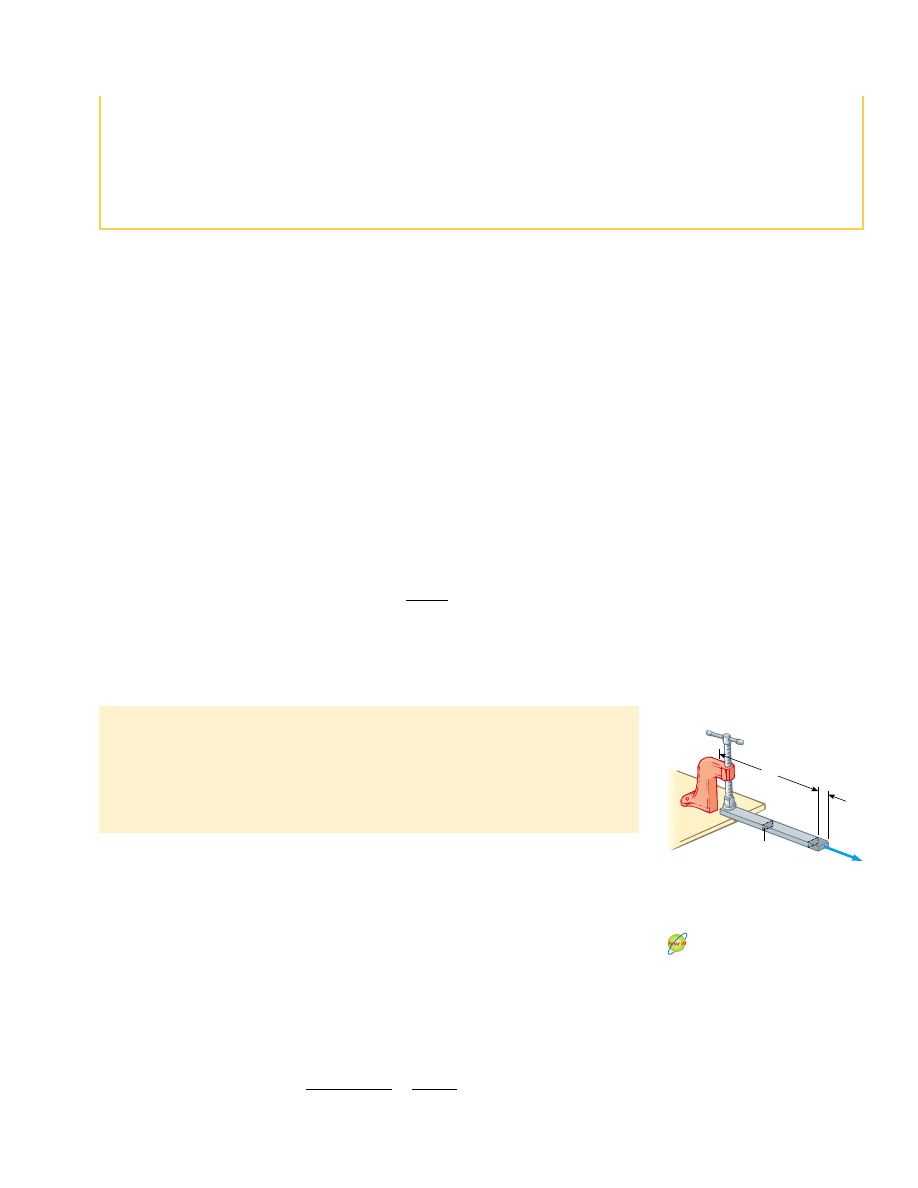
Consider a long bar of cross-sectional area A and initial length L
i
that is clamped at
one end, as in Figure 12.14. When an external force is applied perpendicular to the
cross section, internal forces in the bar resist distortion (“stretching”), but the bar
reaches an equilibrium situation in which its final length L
f
is greater than L
i
and in
which the external force is exactly balanced by internal forces. In such a situation, the
bar is said to be stressed. We define the
tensile stress as the ratio of the magnitude of
the external force F to the cross-sectional area A. The
tensile strain in this case is de-
fined as the ratio of the change in length .L to the original length L
i
. We define
Young’s modulus by a combination of these two ratios:
(12.6)
Y
$
tensile stress
tensile strain
!
F/A
∆L/L
i
1. Young’s modulus, which measures the resistance of a solid to a change in its
length
2. Shear modulus, which measures the resistance to motion of the planes within a
solid parallel to each other
3. Bulk modulus, which measures the resistance of solids or liquids to changes in
their volume
F
A
L
i
∆L
Active Figure 12.14 A long bar
clamped at one end is stretched by
an amount .L under the action of
a force F.
At the Active Figures link
at http://www.pse6.com, you
can adjust the values of the
applied force and Young’s
modulus to observe the
change in length of the bar.
break suddenly.) On the basis of symmetry, we assert that
F
CB
!
F
CD
and F
CA
!
F
CE
:
Finally, we balance the horizontal forces on B, assuming that
strut BD is in compression:
F
CB
!
7 200 N
!
F
y
!
2 F
CB
sin 30* ' 7 200 N ! 0
Thus, the top bar in a bridge of this design must be very
strong.
F
BD
!
12 000 N
(7 200 N) cos 30* $ (7 200 N) cos 30* ' F
BD
!
0
!
F
x
!
F
BA
cos 30* $ F
BC
cos 30* ' F
BD
!
0
Young’s modulus