KTM (690 Enduro EU, 690 Enduro AUS/UK, 690 Enduro USA). Manual - part 18
 

  Index      Manuals     KTM (690 Enduro EU, 690 Enduro AUS/UK, 690 Enduro USA). Repair Manual 2010 year


Search            


Content   ..  16  17  18  19   ..


KTM (690 Enduro EU, 690 Enduro AUS/UK, 690 Enduro USA). Manual - part 18


30/ASSEMBLING THE ENGINE

141

20.10

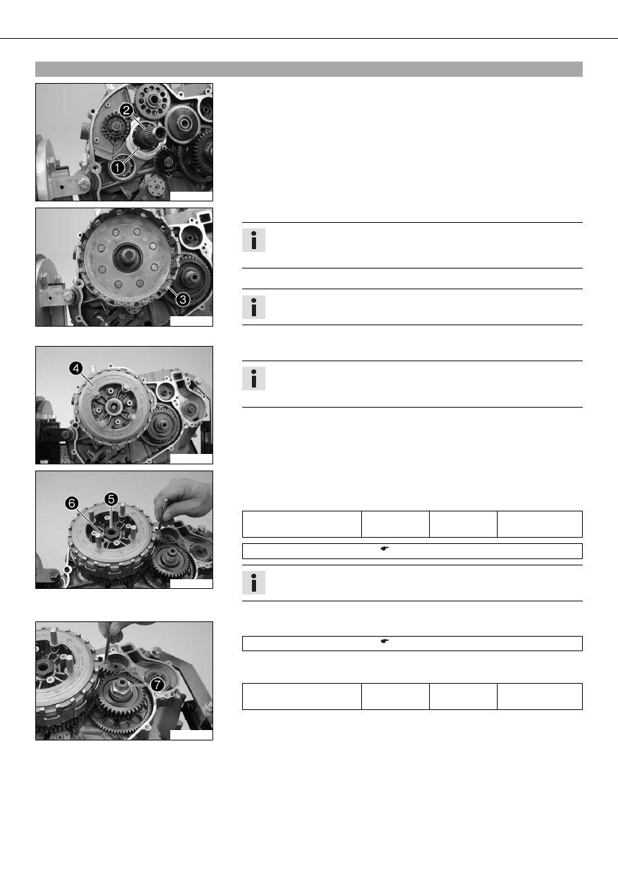
Installing clutch cage

300057-10

– Install supporting plate

and needle bearing

.

300058-10

– Install the clutch cage

.

Info

Turn the clutch cage and oil pump gear wheels backwards and forwards
slightly to help them mesh more easily.

– Mount the half washers with the sharp edge facing outward.

Info

Grease the half washers to ease assembly.

– Position the stepped washer with the cut-out towards the half washers.

302123-10

– Insert the clutch package

in the clutch cage.

Info

If necessary, turn the main shaft a little to ease access.
Make sure that the upper clutch disc is offset by one notch.

302121-10

– Position a new lock washer and install the nut

.

– Lock the clutch cage and primary gear using the special tool, and tighten the nut.

Guideline

Nut, inner clutch hub

M20x1.5

100 Nm
(73.8 lbf ft)

Loctite

®

243™

Gear segment (75029081000) (

p. 218)

Info

Make sure that the crankshaft is not blocked.

– Secure the nut with the lock washer

.

302122-10

– Lock the clutch cage and primary gear using the special tool.

Gear segment (75029081000) (

p. 218)

– Mount and tighten the nut

.

Guideline

Nut, primary gear

M20LHx1.5

90 Nm
(66.4 lbf ft)

Loctite

®

243™

30/ASSEMBLING THE ENGINE

142

300061-10

– Insert the pressure piece

.

300052-11

– Place the pressure cap on.
– Install and tighten the screws

with the spring retainers and clutch springs.

Guideline

Screw, clutch spring

M5

6 Nm (4.4 lbf ft)

– Remove the special tool.

20.11

Installing crankshaft position sensor

300151-10

– Position the crankshaft position sensor

.

– Mount screws but do not tighten them yet.

Guideline

Screw, ignition pulse gen-
erator

M6

10 Nm
(7.4 lbf ft)

Loctite

®

243™

– Position the cable and push the cable support sleeve

into the engine case.

20.12

Installing timing chain and timing chain sprocket

300150-10

– Heat the timing chain sprocket and push it immediately on to the crankshaft.

Guideline

100 °C (212 °F)

– Mount lock ring

.

300148-11

– Thread the timing chain

in and lay it over the timing chain sprocket.

Info

If the timing chain is not new, pay attention to the direction of travel.

30/ASSEMBLING THE ENGINE

143

20.13

Installing timing chain rails

300046-11

– Position the timing chain securing guide

.

Info

The cable of the crankshaft position sensor must be laid in the cable chan-
nel of the timing chain securing guide.

– Thread in the timing chain tensioning rail

from above. Insert the support bush-

ing into the timing chain securing guide.

300045-11

– Thread in the timing chain guide rail

from above. Insert the support bushing into

the timing chain securing guide.

– Mount and tighten screws

.

Guideline

Screw, timing chain guide
rail

M6

10 Nm
(7.4 lbf ft)

Loctite

®

243™

Screw, timing chain ten-
sioning rail

M6

10 Nm
(7.4 lbf ft)

Loctite

®

243™

Info

Ensure that there is no thread locking material at the collar of the screw;
otherwise, the timing chain tension rail could lock and break.

– Check both timing chain rails for freedom of motion.

20.14

Installing rotor

300042-10

– Ensure that the spring washer

is seated properly.

– Degrease the cone of the crankshaft and the rotor.
– Mount the rotor.

Info

Make sure that the crankshaft is not blocked.

– Use the special tool to hold the rotor tight.

Holding spanner (75029091000) (

p. 219)

300043-10

– Mount the tab washer and the nut

. Tighten nut.

Guideline

Rotor nut

M18x1.5

100 Nm
(73.8 lbf ft)

20.15

Adjusting crankshaft position sensor distance

300048-10

– Adjust the distance between the crankshaft position sensor

and the conductive

element of the rotor using the special tool

.

Guideline

Crankshaft position sensor/rotor - dis-
tance

0.70 mm (0.0276 in)

Feeler gauge (59029041100) (

p. 214)

– Fully tighten screws

.

Guideline

Screw, ignition pulse gen-
erator

M6

10 Nm
(7.4 lbf ft)

Loctite

®

243™

30/ASSEMBLING THE ENGINE

144

20.16

Setting engine to top dead center

300025-10

– Set the crankshaft to top dead center and lock it with the special tool

.

Engine blocking screw (77329010000) (

p. 219)

20.17

Installing piston

300032-10

– Shift the joint of the piston rings by 120°.
– Push the oiled piston into the special tool.

Piston assembly ring (75029015102) (

p. 215)

300033-10

– Position the piston on the cylinder using the special tool.
– Push the piston carefully into the cylinder from above.

The piston rings should not become caught; otherwise, they may be damaged.

300035-10

– Ensure that piston marking

faces the outfeed side.

300034-10

– Apply a thin layer of sealing compound in area

.

Loctite

®

5910

– Place the cylinder base gasket on.

Info

Make sure the grooved pins are seated correctly.

30/ASSEMBLING THE ENGINE

145

300036-10

– Cover the engine case opening with a cloth. Thread the timing chain through the

chain shaft. Mount the piston pin.

Info

For clarity, the following steps are illustrated using a disassembled piston.

400366-10

– Position the piston pin retainer.

300038-10

– Insert the special tool and firmly press it toward the piston.
– Turn the special tool counterclockwise, thereby pressing the piston pin retainer into

the groove.

Piston pin lock ring insert (75029035000) (

p. 216)

– Make sure that the piston pin retainer is seated correctly on both sides.

300039-10

– Remove the cloth.
– Keep the timing chain tensioned. Push the cylinder down carefully and let the

grooved pins engage.

20.18

Installing cylinder head

300029-11

– Put on the cylinder head gasket.

Info

Make sure the grooved pins are seated correctly.

– Mount the cylinder head. Mount and tighten cylinder head screw

with the wash-

ers.

30/ASSEMBLING THE ENGINE

146

Guideline

Cylinder head screw

M10

Tightening
sequence:
Tighten diag-
onally, begin-
ning with the
rear screw
on the chain
shaft.
Step 1
15 Nm
(11.1 lbf ft)
Step 2
30 Nm
(22.1 lbf ft)
Step 3
45 Nm
(33.2 lbf ft)
Step 4
60 Nm
(44.3 lbf ft)

Lubricated with
engine oil

Info

Always use new cylinder head screws.

– Mount and tighten screws

.

Guideline

Screw, cylinder head

M6

10 Nm
(7.4 lbf ft)

Loctite

®

243™

20.19

Installing camshafts

300163-10

– Lay the timing chain over the camshaft. Push the timing chain into the bearing

seats. The middle drill hole of the camshaft

and the drill hole of the cylinder

head

must be aligned.

Info

Make sure that the crankshaft is at top dead center.

300022-10

– Position the camshaft support plate

. Mount and tighten screw

.

Guideline

Screw, camshaft support
plate

M6

10 Nm
(7.4 lbf ft)

Loctite

®

243™

20.20

Installing timing chain tensioner

300017-11

– Insert the timing chain tensioner

.

– Mount and tighten plug

with the new seal ring.

Guideline

Plug, timing chain tensioner

M20x1.5

25 Nm
(18.4 lbf ft)

30/ASSEMBLING THE ENGINE

147

300018-10

– Remove screw

and use the special tool to push the timing chain tensioner

toward the timing chain.

Release device for timing chain tensioner (77329051000) (

p. 220)

The timing chain tensioner unlocks.

– Mount and tighten screw

.

Guideline

Screw, unlocking of timing chain ten-
sioner

M10x1

10 Nm (7.4 lbf ft)

20.21

Checking valve clearance

300044-10

– Remove special tool

.

– Crank the engine several times.
– Set the engine to ignition top dead center. ( p. 101)

300155-10

– Check the valve clearance on all valves between the valve and the rocker arm using

the special tool

.

Guideline

Valve play, cold

0.07… 0.13 mm (0.0028…
0.0051 in)

Feeler gauge (59029041100) (

p. 214)

» If valve clearance does not meet specifications:

– Adjust the valve clearance. (

p. 147)

20.22

Adjusting valve clearance

300156-10

– Remove screws

.

Info

Make sure that the crankshaft is at top dead center.

300157-10

– Screw suitable screws

into the rocker arm shafts

. Pull out the rocker arm

shafts.

– Take off the rocker arm.

30/ASSEMBLING THE ENGINE

148

300158-10

– Remove shims

and set them down according to the installation position.

– Correct the shims as indicated by the results of the valve clearance check.
– Insert suitable shims.
– Position the rocker arms and push in the rocker arm shafts.

Info

Make sure that the tapped hole of the rocker arm shaft is positioned facing
outwards.
The small drill hole and the flat surface must point upwards.

300156-11

– Install and tighten the screws

of the rocker arm shafts.

Guideline

Screw, rocker arm shaft

M6

12 Nm (8.9 lbf ft)

– Check the valve clearance. (

p. 147)

20.23

Installing spark plug

300016-11

– Mount and tighten the spark plug

using the special tool.

Guideline

Spark plug

M12x1.25

17 Nm
(12.5 lbf ft)

Spark plug wrench (75029172000) (

p. 219)

20.24

Installing spacer and spring

300154-10

– Install the spacer

and spring

of the shift shaft.

20.25

Installing clutch cover

300015-11

– Mount the dowels. Put on the clutch cover seal.
– Position the clutch cover. Mount and tighten screws

.

Guideline

Screw, clutch cover

M6

10 Nm (7.4 lbf ft)


Content   ..  16  17  18  19   ..