KTM (690 Enduro EU, 690 Enduro AUS/UK, 690 Enduro USA). Manual - part 17
 

  Index      Manuals     KTM (690 Enduro EU, 690 Enduro AUS/UK, 690 Enduro USA). Repair Manual 2010 year


Search            


Content   ..  15  16  17  18   ..


KTM (690 Enduro EU, 690 Enduro AUS/UK, 690 Enduro USA). Manual - part 17


30/ENGINE - WORK ON INDIVIDUAL PARTS

133

19.38

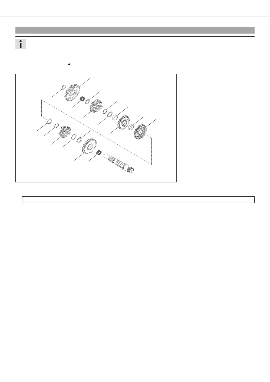
Assembling countershaft

Info

Use new lock rings in every repair job.

– Oil all parts carefully before assembling.
– Check the transmission. (

p. 131)

1

1

2

2

4

4

5

5

6

6

7

7

9

9

8

8

bl

bl

bk

bk

bm

bm

8

8

bo

bo

bn

bn

bp

bp

bq

bq

br

br

3

3

300128-02

– Fix the countershaft in the vise with the geared end facing downward.

Guideline

Use soft jaws

– Mount needle bearing

and the second-gear idler gear

on the countershaft with the protruding collar facing downward.

– Mount stop disk

and lock ring

.

– Mount the sixth-gear sliding gear

with the shift groove facing upward.

– Install lock ring

and stop disk

.

– Mount needle bearing

and the fourth-gear idler gear

with the collar facing upward.

– Mount needle bearing



and the third-gear idler gear



with the collar facing downward.

– Install stop disk



and lock ring



.

– Mount the fifth-gear sliding gear



with the shift groove facing downward and stop disk



.

– Mount needle bearing



, first-gear idler gear



with the groove facing downward and stop disk



.

– Finally, check all gear wheels for smooth operation.

30/ENGINE - WORK ON INDIVIDUAL PARTS

134

19.39

Checking electric starter drive

5

5

6

6

1

1

2

2

4

4

3

3

300129-01

– Check the teeth and seating of the starter idler gear

for damage and wear.

» If there is damage or wear:

– Replace the starter idler gear and/or needle bushing.

– Check the teeth and seating of the torque limiter

for damage and wear.

» If there is damage or wear:

– Replace the torque limiter and/or needle bushing.

– Check freewheel gear

and bearing when removed for damage and wear.

» If there is damage or wear:

– Replace the freewheel gear and/or the bearing.

– Check the freewheel

when removed for damage and wear.

» If there is damage or wear:

– Replace the freewheel.

– Check the toothing of the starter motor

for damage and wear.

» If there is damage or wear:

– Replace the starter motor.

– Clamp the minus (negative) cable of a 12 Volt power supply to the starter motor housing. Briefly connect the plus (positive) cable

of the power supply to the starter motor connection.
» If the starter motor does not turn when you close the power circuit:

– Replace the starter motor.

– Replace the O-ring

of the starter motor.

19.40

Removing freewheel

300127-10

– Extract the lock ring

from the groove using suitable pliers.

30/ENGINE - WORK ON INDIVIDUAL PARTS

135

300128-10

– Compress the expansion ring

and remove it, using suitable pliers.

– Take the freewheel

out of the primary gear.

19.41

Checking freewheel

300131-10

– Insert the freewheel gear

in the primary gear

, turning the primary gear clock-

wise; do not twist!

– Check the locking action of the freewheel gear

.

» If the primary gear does not turn clockwise or if it does not lock counterclock-

wise:
– Remove the freewheel. (

p. 134)

– Turn the freewheel 180°.
– Install the freewheel. (

p. 135)

19.42

Installing freewheel

300129-10

– Lubricate all parts thoroughly.
– Push the freewheel

into the primary gear.

Info

Note the direction of rotation.

300128-11

– Install the expansion ring

.

300130-10

– Make sure that all lugs of the expansion ring locate in the slits

of the freewheel.

Info

If necessary, use a screwdriver to ease them in.

30/ENGINE - WORK ON INDIVIDUAL PARTS

136

300127-11

– Insert the lock ring

into the groove with suitable pliers and check that it is

seated correctly.

30/ASSEMBLING THE ENGINE

137

20.1

Installing transmission shafts

300087-10

– Clamp the right section of the engine case.

Holder for engine work stand (75012001070) (

p. 215)

Support for engine work stand (75012001060) (

p. 215)

Engine work stand (61229001000) (

p. 215)

– Make sure that both stop disks

are installed.

– Mount the inner bearing race

on the countershaft.

300088-10

– Lubricate all bearings.
– Assemble the two transmission shafts and slide them into the bearing seats

together.

300089-10

– Mount the upper shift fork

, the middle shift fork

, and the lower shift fork

.

Info

For the assembly of the middle shift fork

, the sliding gear of the

third/fourth gear must be lifted.

300090-10

– Insert shift drum

into the bearing seat.

– Hang the shift forks into the shift drum.

300079-11

– Install the shift rail

.

– Check the transmission for smooth operation.

300082-11

– Install the shim

and lock ring of the countershaft.

30/ASSEMBLING THE ENGINE

138

20.2

Installing crankshaft and balancer shaft

300085-10

– Mount the special tool

on the alternator side of the crankshaft.

Mounting sleeve (75029080000) (

p. 218)

– Mount the special tool

on the balancer shaft.

Mounting sleeve (58529005000) (

p. 213)

300165-10

– Push the crankshaft into the bearing seat and take off the special tool.
– Grease the shaft seal rings of the balancer shaft.
– Push the balancer shaft

into the bearing seat and take off the special tool.

Align marks

and

.

– Mount stop disk

.

20.3

Installing left engine case

300077-11

– Mount the dowels.
– Mount the O-ring

.

– Degrease the sealing area. Apply the sealing compound to the left engine case half.

Loctite

®

5910

300075-11

– Put on the left engine case half. If necessary, tap lightly with a rubber mallet and

turn the transmission shafts.

Info

Do not tighten the engine case sections using the screws.

– Install the screws

and tighten them diagonally.

Guideline

Screw, engine case

M6

10 Nm (7.4 lbf ft)

Info

Install the screw in the oil filter housing with a new copper washer.

30/ASSEMBLING THE ENGINE

139

20.4

Installing oil pumps

300073-10

– Install pins and internal rotors on both oil pump shafts.
– Mount external rotors in the engine case.

The marking is not visible after mounting.

– Mount the oil pump shafts

with internal rotors

.

The marking

is visible after mounting.

– Oil the parts.

300071-11

– Position both oil pump covers

. Mount and tighten the screws.

Guideline

Screw, oil pump cover

M5

6 Nm
(4.4 lbf ft)

Loctite

®

243™

– Install washers

and pins

.

300070-11

– Mount the oil pump gears

, washers

and lock washers

.

20.5

Installing locking lever

300069-11

– Position locking lever

with sleeve and spring

.

– Mount and tighten screw

.

Guideline

Screw, locking lever

M6

10 Nm
(7.4 lbf ft)

Loctite

®

243™

20.6

Installing shift drum locating

300068-10

– Press locking lever

down and position shift drum locating.

Info

The flat surfaces

of the shift drum locating are not symmetric.

30/ASSEMBLING THE ENGINE

140

300067-11

– Release the locking lever.
– Mount and tighten screw

.

Guideline

Screw, shift drum locating

M6

10 Nm
(7.4 lbf ft)

Loctite

®

243™

20.7

Installing shift shaft

300066-11

– Slide shift shaft

with the washer into the bearing seat.

– Push sliding plate

away from the shift drum locating

. Insert the shift shaft all

the way.

– Let the sliding plate engage in the shift drum locating.
– Shift through the transmission.

20.8

Installing starter drive

300065-11

– Install the two needle bearings

and the woodruff key

.

– Push on the freewheel gear

.

300064-11

– Push on the starter idler gear

with washer. Mount lock ring.

– Push on the needle bearing and torque limiter

with washer. Mount lock ring.

20.9

Installing primary gear

300063-10

– Ensure that the spring washer is seated properly.
– Mount primary gear

.

Info

Turn the freewheel gear backwards and forwards to ease meshing.


Content   ..  15  16  17  18   ..