KTM (690 Enduro EU, 690 Enduro AUS/UK, 690 Enduro USA). Manual - part 4
 

  Index      Manuals     KTM (690 Enduro EU, 690 Enduro AUS/UK, 690 Enduro USA). Repair Manual 2010 year


Search            


Content   ..  2  3  4  5   ..


KTM (690 Enduro EU, 690 Enduro AUS/UK, 690 Enduro USA). Manual - part 4


01/FORK, TRIPLE CLAMP

29

Alternative 2

Warning

Danger of accidents Modifications to the suspension settings can seri-
ously alter the vehicle's ride behavior.
– Extreme modifications to the adjustment of the spring elements can

cause a serious deterioration in the handling characteristics and
overload some components.

– Only make adjustments within the recommended range.
– After making adjustments, ride slowly at first to get the feel of the

new ride behavior.

– Turn the adjusting screws to the position they were in before dismantling.

– Mount protection cap

.

5.17

Checking the steering head bearing play

Warning

Danger of accidents Unstable vehicle handling from incorrect steering head bearing play.
– Adjust the steering head bearing play without delay.

Info

If the bike is driven for a longer time with play in the steering head bearing, the bearing and the bearing seats in the frame can
be damaged after time.

– Raise the motorcycle with the lift stand. ( p. 9)

100298-10

– Move the handlebar to the straight-ahead position. Move the fork legs to and fro in

the direction of travel.

No play should be noticeable in the steering head bearing.

» If there is noticeable play present:

– Adjust the play of the steering head bearing. ( p. 29)

– Move the handlebar to and fro over the entire steering range.

The handlebar must be able to move easily over the entire steering range. No
resting locations should be noticeable.

» If click positions are noticeable:

– Adjust the play of the steering head bearing. ( p. 29)
– Check the steering head bearing and change if necessary.

– Remove the motorcycle from the lift stand. ( p. 9)

5.18

Adjusting the play of the steering head bearing

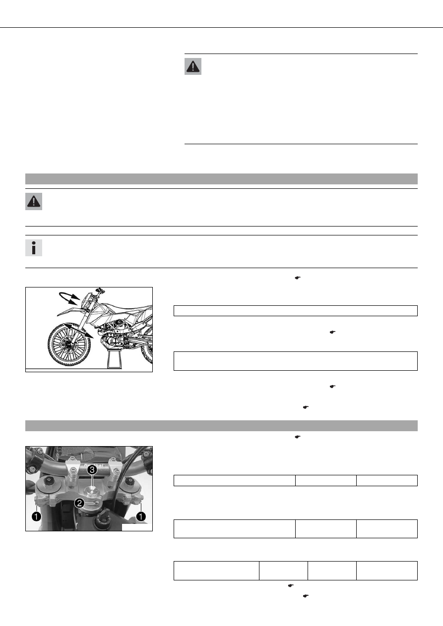
– Raise the motorcycle with the lift stand. ( p. 9)

100297-10

– Loosen screw

. Remove screw

.

– Loosen and retighten screw

.

Guideline

Screw, top steering head

M20x1.5

10 Nm (7.4 lbf ft)

– Using a plastic hammer, tap lightly on the upper triple clamp to avoid strains.
– Fully tighten screws

.

Guideline

Screw, top triple clamp

M8

17 Nm
(12.5 lbf ft)

– Mount and tighten screw

.

Guideline

Screw, steering stem

M8

20 Nm
(14.8 lbf ft)

Loctite

®

243™

– Check the steering head bearing play. ( p. 29)
– Remove the motorcycle from the lift stand. ( p. 9)

02/HANDLEBAR, INSTRUMENTS

30

6.1

Handlebar position

0

0

B

B

0

0

A

A

400271-11

On the upper triple clamp, there are 2 holes at a distance

to each other.

Distance

between holes

15 mm (0.59 in)

The holes on the handlebar support are placed at a distance

from the center.

Distance

between holes

3.5 mm (0.138 in)

The handlebar can be mounted in 4 different positions. In this way, the handlebar can
be installed in the position most comfortable for the rider.

6.2

Adjusting handlebar position

0

0

2

2

0

0

1

1

400271-10

– Remove the four screws

. Remove the handlebar clamp. Remove the handlebar

and lay it to one side.

Info

Protect the motorcycle and its attachments from damage by covering them.
Do not bend the cables and lines.

– Remove the two screws

. Remove the handlebar support.

– Place the handlebar support in the required position. Fit and tighten the two

screws

.

Guideline

Screw, handlebar support

M10

40 Nm
(29.5 lbf ft)

Info

Position the left and right handlebar supports evenly.

– Position the handlebar.

Info

Make sure cables and wiring are positioned correctly.

– Position the handlebar clamp. Fit and evenly tighten the four screws

.

Guideline

Screw, handlebar clamp

M8

20 Nm
(14.8 lbf ft)

Loctite

®

243™

6.3

Checking the play in the throttle cable

400192-10

– Move the handlebar to the straight-ahead position. Move the throttle grip back-

wards and forwards to ascertain the play in the throttle cable.

Throttle cable play

3… 5 mm (0.12… 0.2 in)

» If the throttle cable play does not meet specifications:

– Adjust the play in the throttle cable. ( p. 31)

Danger

Danger of poisoning Exhaust gases are poisonous and inhaling them may
result in unconsciousness and/or death.
– When running the engine, always make sure there is sufficient ventila-

tion, and do not start or run the engine in an enclosed space without an
effective exhaust extraction system.

– Start the engine and let it run idle. Move the handlebar to and fro over the entire

steering range.

The idle speed must not change.

» If the idle speed changes:

02/HANDLEBAR, INSTRUMENTS

31

– Adjust the play in the throttle cable. ( p. 31)

6.4

Adjusting the play in the throttle cable

100280-10

– Move the handlebar to the straight-ahead position.
– Use the KTM diagnostics tool to set the motor drive to the basic position.
– Loosen counter nut

.

– Set the play in the throttle cable by turning the adjusting screw

.

Guideline

Throttle cable play

3… 5 mm (0.12… 0.2 in)

– Tighten counter nut

.

03/FRAME

32

7.1

Removing the engine guard

– Stand the motorcycle on its side stand on a horizontal surface.

100198-10

– Remove screws

on the left and right.

– Pull the engine guard forward out of the holders and set it down.

7.2

Installing the engine guard

100199-10

– Slide the engine guard into holders

at the rear.

– Position the engine guard. Mount and tighten screws.

Guideline

Remaining screws, chassis

M6

10 Nm (7.4 lbf ft)

04/SHOCK ABSORBER, SWINGARM

33

8.1

Adjusting high-speed compression damping of the shock absorber

Danger

Danger of accidents Disassembly of pressurized parts can lead to injury.
– The shock absorber is filled with high density nitrogen. Adhere to the description provided.

Info

The high-speed setting can be seen during the fast compression of the shock absorber.

100246-10

– Turn adjusting screw

all the way clockwise using a socket wrench.

Info

Do not loosen nut

!

– Turn back counterclockwise the number of turns corresponding to the shock

absorber type.
Guideline

Compression damping, high-speed

Comfort

2 turns

Standard

1.5 turns

Sport

1 turn

Full payload

1 turn

Info

Turn clockwise to increase damping, turn counterclockwise to reduce sus-
pension damping.

8.2

Adjusting the low-speed compression damping of the shock absorber

Danger

Danger of accidents Disassembly of pressurized parts can lead to injury.
– The shock absorber is filled with high density nitrogen. Adhere to the description provided.

Info

The low-speed setting can be seen during the slow to normal compression of the shock absorber.

100245-10

– Turn adjusting screw

clockwise with a screwdriver up to the last perceptible

click.

Info

Do not loosen nut

!

– Turn back counterclockwise the number of clicks corresponding to the shock

absorber type.
Guideline

Compression damping, low-speed

Comfort

20 clicks

Standard

15 clicks

Sport

10 clicks

Full payload

10 clicks

Info

Turn clockwise to increase damping, turn counterclockwise to reduce sus-
pension damping.

04/SHOCK ABSORBER, SWINGARM

34

8.3

Adjusting rebound damping of the shock absorber

Danger

Danger of accidents Disassembly of pressurized parts can lead to injury.
– The shock absorber is filled with high density nitrogen. Adhere to the description provided.

100247-10

– Turn adjusting screw

clockwise up to the last perceptible click.

– Turn back counterclockwise the number of clicks corresponding to the shock

absorber type.
Guideline

Rebound damping

Comfort

20 clicks

Standard

15 clicks

Sport

10 clicks

Full payload

10 clicks

Info

Turn clockwise to increase damping, turn counterclockwise to reduce sus-
pension damping.

8.4

Measuring the unloaded rear wheel sag

– Raise the motorcycle with the lift stand. ( p. 9)

0

0

A

A

400988-10

– Measure the vertical distance between the rear axle and a fixed point such as a

marking on the side cover.

– Note down the value as dimension

.

– Remove the motorcycle from the lift stand. ( p. 9)

8.5

Checking the static sag of the shock absorber

0

0

A

A

0

0

B

B

400989-10

– Measure distance

of rear wheel unloaded. (

p. 34)

– Hold the motorcycle upright with the aid of an assistant.
– Measure the distance between the rear axle and the fixed point again.
– Note down the value as dimension

.

Info

The static sag is the difference between measurements

and

.

– Check the static sag.

Static sag

25 mm (0.98 in)

» If the static sag is less or more than the specified value:

– Adjust the spring preload of the shock absorber. ( p. 35)

04/SHOCK ABSORBER, SWINGARM

35

8.6

Checking the riding sag of the shock absorber

0

0

A

A

0

0

C

C

400990-10

– Measure distance

of rear wheel unloaded. (

p. 34)

– With another person holding the motorcycle, the rider, wearing full protective cloth-

ing, sits on the seat in a normal sitting position (feet on footrests) and bounces up
and down a few times.

The rear wheel suspension levels out.

– Another person now measures the distance between the rear axle and a fixed point.
– Note down the value as dimension

.

Info

The riding sag is the difference between measurements

and

.

– Check the riding sag.

Riding sag

80… 90 mm (3.15… 3.54 in)

» If the riding sag differs from the specified measurement:

– Adjust the riding sag. (

p. 36)

8.7

Adjusting the spring preload of the shock absorber

Danger

Danger of accidents Disassembly of pressurized parts can lead to injury.
– The shock absorber is filled with high density nitrogen. Adhere to the description provided.

Info

Before changing the spring preload, make a note of the present setting, e.g., by measuring the length of the spring.

– Remove the shock absorber. (

p. 36)

– After removing the shock absorber, clean it thoroughly.

700541-01

– Loosen locking ring

.

– Turn adjusting ring

until the spring is no longer under tension.

Hook wrench (T106S) (

p. 220)

– Measure the overall spring length without a load.
– Tension the spring by turning the adjusting ring

to the prescribed value.

Guideline

Spring preload

19 mm (0.75 in)

Info

Depending on the static sag and/or the riding sag, it may be necessary to
increase or decrease the spring preload.

– Tighten locking ring

.

– Install the shock absorber. (

p. 37)

04/SHOCK ABSORBER, SWINGARM

36

8.8

Adjusting the riding sag

– Remove the shock absorber. (

p. 36)

– After removing the shock absorber, clean it thoroughly.

201352-10

– Choose and mount a suitable spring.

Guideline

Spring rate

Soft

75 N/mm (428 lb/in)

Medium (standard)

80 N/mm (457 lb/in)

Hard

85 N/mm (485 lb/in)

Info

The spring rate is shown on the outside of the spring.

– Install the shock absorber. (

p. 37)

– Check the static sag of the shock absorber. ( p. 34)
– Adjust the rebound damping of the shock absorber. ( p. 34)

8.9

Removing the shock absorber

– Raise the motorcycle with the work stand. ( p. 9)

300562-10

– Remove screws

.

300563-10

– Lift the rear fairing.
– Remove screws

.

300564-10

– Remove screw

.

– Repeat the operation on the opposite side.


Content   ..  2  3  4  5   ..