BMW Motorcycle (R1100RT, R1100RS, R850/1100GS, R850/1100R). Manual - part 20
 

  Index      Manuals     BMW AG Motorcycle (R1100RT, R1100RS, R850/1100GS, R850/1100R). Repair Manual


Search            


Content   ..  18  19  20  21   ..


BMW Motorcycle (R1100RT, R1100RS, R850/1100GS, R850/1100R). Manual - part 20


12.9

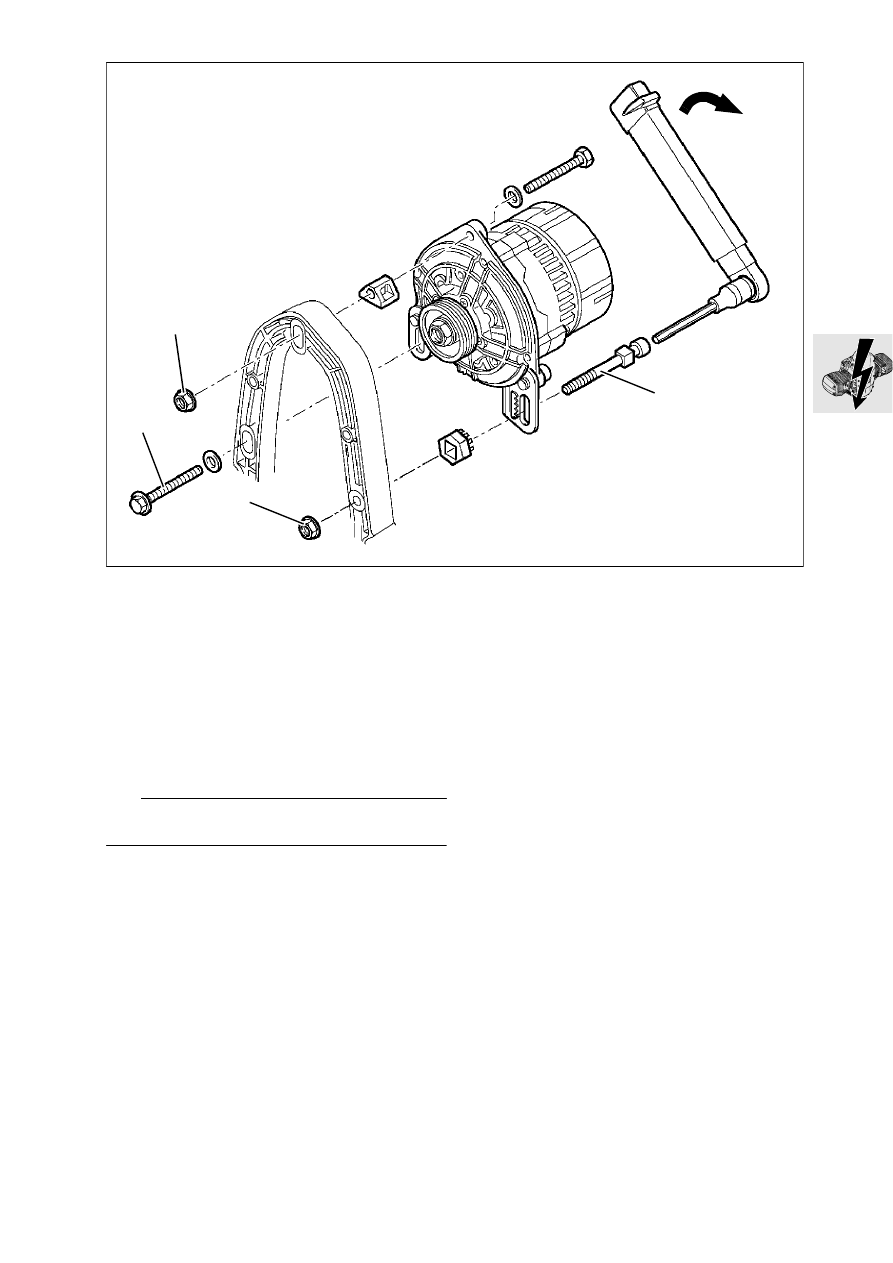
Adjusting procedure for Poly-V belt:
Poly-V belt installation procedure:

Place the Poly-V belt in position, tension it, turn 
the engine over once, then relieve belt tension

Poly-V belt tensioning procedure:

Loosen alternator mount (1, 2, 3).

Screw up hex nut (1) at adjusting screw (4) lightly 
by hand (using no tools)

Tighten adjusting screw (4) using torque wrench; 
fully tighten retaining nut (3), slacken off adjusting 
screw and tighten down screws.

L

  Note:

Siehe auch Serviceinformation 12 020 95 (700).

X

 Tightening torque:

Poly-V belt preload ......................................... 8 Nm
Alternatorto alternator support cover............ 20 Nm
Positive lead to alternator ............................. 15 Nm
Belt pulley at alternator................................. 50 Nm

2

3

1

4

RS110480

12.10

Dismantling/reassembling alterna-
tor

Take out the cover retaining screws (1).

Release clips (2) and remove the cover.

Remove voltage regulator (3). 

Remove the Poly-V belt pulley.

Install in the reverse order of work.

X

 Tightening torque:

Belt pulley at alternator................................. 50 Nm

3

2

1

RS120050

12.11

Checking alternator

L

  Note:

Before each 

 measurement, calibrate to zero with 

the BMW diagnosis tester:
Connect the positive (yellow) and negative (green) 
leads together. 

-key is to be pressed until the dig-

ital display reads 0.00 

.

Using BMW Diagnosis tester, 
BMW No. 61 1 510, measure resistance between 
the sliprings.

Nominal resistance:......................................... 3 

Checking armature for short to ground 
(earth)

Measure resistance between sliprings and arma-
ture

Measured result:.............................OL = open line

RS120070

OL

RS120060

12.12

Removing and installing starter 
motor

Remove dualseat.

[RS/RT] Remove left side section of fairing.

e

  Caution:

Disconnect ground (earth) lead from battery. Insu-
late ground (earth) lead.

[RS/GS/R] Remove cover (1) for starter motor 
and pull off wire (2) for power socket.

Detach connecting lead (3).

Take out retaining screws (4) and remove the 
starter motor.

Install in the reverse order of work.

X

 Tightening torque:

Starter motor to engine ................................ 20 Nm 
Starter motor cover to gearbox housing ......... 7 Nm
Positive lead to starter motor........................ 10 Nm

1

2

4

4

3

RS120140

12.13

Dismantling/reassembling starter 
motor

Detach lead (1).

Remove retaining screws (2).

Remove flange (3).

Remove solenoid switch (4) after taking out the 
retaining screws (5).

Remove release lever (6) and spring (7) from so-
lenoid switch (8).

Remove retaining ring (9) and take starter motor 
gear assembly (10) off shaft.

Install in the reverse order of work.

Coat the steep-angle thread and the engaging 
ring with Bosch PZ 2 V 3 silicone grease.

Renewing carbon brushes

Detach lead (1).

Remove cover (11).

Remove holder (12) for carbon brushes.

Lift up retaining springs (13) and remove carbon 
brushes (14).

Install carbon brushes with retaining plate.

Slide short lead (15) on to threaded pin.

Install cover (11).

Attach lead (1).

Checking starter motor

Engine temperature 

20 °C

Ammeter in positive lead to starter motor.

Starter is in good working order at:

............................................................app. 80...150 A

Voltmeter connected to (+) and (-) on starter mo-
tor

Starter is in good working order at:

.........................................................app. 10...11 V

Checking starter relay

L

  Note:

Before each 

 measurement, calibrate to zero with 

the BMW diagnosis tester:
Connect the positive (yellow) and negative (green) 
leads. Press the 

 key until the digital display reads 

0.00 

.

After calibation, insert the 

 meter between 

terminals 30 and 87.

 value ..............................................................0

 Ω

Connect positive supply to terminal 85 and neg-
ative supply to terminal 86. Then:
Connect (+) to terminal 85, (-) to terminal 86b.

The relay must be energized.

 value: ............................................................ 0 

1

11

13

15

12

10

9

3

2

6

8

7

4

14

5

RS120080

12.14

Removing and installing magnetic 
gate

Remove dualseat.

[RS/GS/RT] Remove side sections of fairing.

[RS] Remove inner fairing panel at fuel tank.

[R] Remove tank cover.

Unscrew fuel tank mount and carefully move the 
tank to the rear.

e

  Caution:

Do not scratch paint; place foam rubber mat or 
similar item under tank.

e

  Caution:

Disconnect ground (earth) lead from battery.
Insulate the ground (earth) lead!

Separate plug connection (1) for magnetic trig-
ger.

Remove front cover from engine.

Slacken off alternator mount (2) and relieve 
tension on Poly-V belt.

[RS/GS/R] Remove starter motor cover/pull off 
power socket lead.

Remove starter motor.

Lock clutch housing with retaining device, 
BMW No. 11 5 640.

5

2

5

1

6

4

3

RS120090

1

RS180050

12.15

Remove rotary breather pipe (3).

Remove pulley (4).

L

  Note:

Ggf. Einbaulage der Magnetschranke für Wiederein-
bau kennzeichnen.

Remove magnetic trigger (5).

Install in reverse order of work.

[from 1995 model year on] Secure rotor (6) of 
Hall-effect gate with Loctite instant adhesive or 
similar to the Poly-V belt.

e

  Caution:

Install lock (7) for belt pulley 
[from 1995 model year on location at Hall-effect 
gate rotor] in groove/crankshaft (7).
Carefully dismantle magnetic trigger lead. Tension 
Poly-V belt according to installation procedure.

X

 Tightening torque:

Pre-tension of Poly–V belt .............................. 8 Nm
Alternatorto alternator mount cover .............. 20 Nm
Belt pulley to crankshaft ............................... 50 Nm

Timing the ignition

Lock the clutch housing with the TDC insert pin, 
BMW No. 11 2 650.

Connect ignition tester, BMW No. 12 3 650, and 
adapter lead, BMW No. 12 3 652, to Hall-effect 
trigger plate.

Slacken off plate of Hall-effect trigger.

Turn plate until telltale lamp just goes out. 

Tighten plate on Hall-effect trigger.

Remove OT (TDC) insert pin.

11 2 650

TDC

RS110461

12 3 650

12 3 652

RS110460

13.1

Contents

Page

13

Technical Data

............................................................................................................................... 3

Removing and installing air cleaner 

...................................................................................7

Removing and installing throttle stub pipe 

....................................................................8

Removing and installing injectors

 ............................................................................................9

Removing and installing Motronic control unit 

...........................................................9

13 Fuel preparation and control


Content   ..  18  19  20  21   ..