BMW Motorcycle (R1100RT, R1100RS, R850/1100GS, R850/1100R). Manual - part 13


  Index      Manuals     BMW AG Motorcycle (R1100RT, R1100RS, R850/1100GS, R850/1100R). Repair Manual


Search            


Content   ..  11  12  13  14   ..


BMW Motorcycle (R1100RT, R1100RS, R850/1100GS, R850/1100R). Manual - part 13


11.52

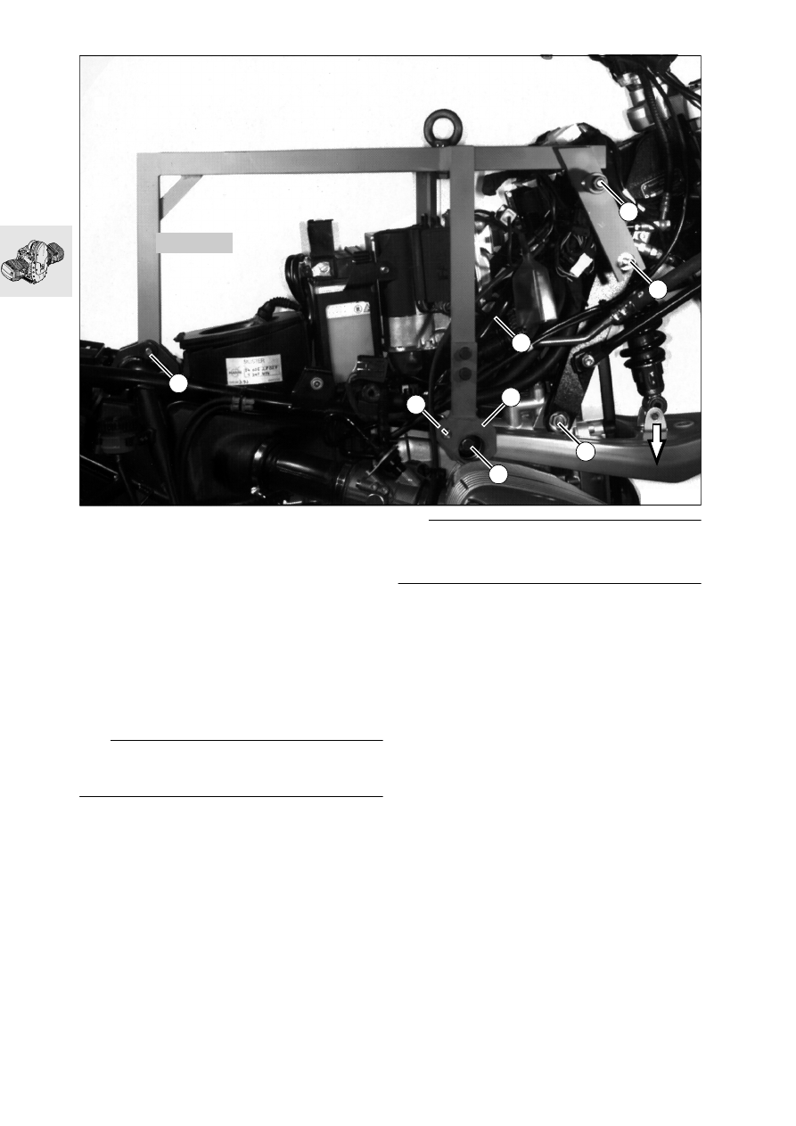
Fitting auxiliary frame

Remove the rear wheel.

Remove rear suspension strut.

Install the rear wheel.

Remove upper retaining screw and lower pin in 
connecting struts (1) between engine and frame.

Attach auxiliary frame, BMW No. 46 5 630, at 
rear suspension strut pivot (2).

Hook the auxiliary frame to the front tank 
mount (3).

Center the auxiliary frame over the plane surface 
of the tank mount, insert threaded bushes (4) ful-
ly into the connecting struts/frame and 
tighten firmly.

e

 Caution:

Protect tank mount with adhesive tape to prevent 
scratching.

Unfasten rear frame screw connection (5) at front 
left/right.

Insert adapter (6) into the leading link/rear frame 
mount and secure it to the auxiliary frame.

Unfasten lower front suspension strut mount.

Press front of leading link down (arrow), or pull 
rear section downwards.

Unscrew and remove pin (7) securing the frame 
to the engine.

e


Caution:

Protect tank mount with adhesive tape to prevent 
scratching.

Secure front suspension strut at bottom.

Detach rear left/right of rear frame.

Detach left intake pipe at cylinder head and pull 
downwards.

Withdraw leading link shaft (8) to the left.

Raise frame assembly at the front.

4

3

1

8

5

6

7

2

46 5 630

RS111010

11.53

Attach frame support, BMW No. 46 5 620, with 
adapter, BMW No. 46 5 623, to the frame unit.

Remove gearbox/swinging arm/rear axle/rear 
wheel together.

Take off auxiliary frame.

Lower frame assembly at the front.

e

 Caution:

Ensure that all components are correctly located. 
Do not damage electrical wiring, leads or wire 
cables.

Detach left intake pipe at cylinder head and pull 
downwards.

Apply a light coating of grease to the leading link 
shaft, insert from the left and secure tightly.

Unfasten lower front suspension strut mount.

Press front of leading link downwards or pull rear 
section downwards.

Using mandrel, BMW No. 46 5 630, align the 
front frame bores with the engine bore from the 
left, insert the pin from the right and screw up 
tightly.

e

 Caution:

Do not scratch leading link - apply adhesive mask-
ing tape if necessary.

Secure front suspension strut at bottom.

Remove auxiliary frame.

46 5 623

46 5 620

RS111020

11.54

Dismantling engine

Attach engine mount, BMW No. 11 0 630, to 
engine block.

Transfer engine to assembly frame.

Drain engine oil.

Remove oil filter, using oil filter wrench, 
BMW No. 11 4 650.

11 0 630

RS110010

11 4 650

RS110950

11.55

Removing cylinder head cover

Unscrew and remove spark plugs with spark 
plug wrench, BMW No. 12 3 510.

Remove cylinder head cover.

e

 Caution:

Trap escaping oil.

12 3 510

RS110020

11.56

Locking the engine in the TDC posi-
tion

Remove front cover.

Turn the belt pulley to move the piston to TDC on 
the ignition stroke.

TDC on ignition stroke:
1. TDC mark is visible, and
2. the inlet and exhaust valves in the cylinder in 

question are closed.

Secure the clutch housing with locking device, 
BMW No. 11 5 640.

L

 Note:

The engine can be set to top dead center with the 
TDC pin,  BMW No. 11 2 650, which is inserted into 
the clutch housing and the engine block at TDC.

RS 11.003

TDC

11 5 640

RS110030

11 2 650

TDC

RS110461

11.57

Removing and installing chain ten-
sioner

e

 Caution:

Do not accidentally confuse the chain tensioner 
pistons. When installing, fit a new gasket.

Assembly specification for timing chain ten-
sioner:

Removal:

Remove timing chain tensioner, then remove 
cam-shaft sprocket from camshaft.

Installation:

First install camshaft sprocket, then timing chain 
tensioner.

e

 Caution:

Failure to observe this sequence can cause the 
chain tensioner piston to fall into the left side of the 
timing chain cavity.

X

 Tightening torque:

Chain tensioner ............................................ 32 Nm

RS110060

11.58

Removing valve gear holder

Remove camshaft sprocket cover.

Unscrew/press off camshaft sprocket.

L

 Note:

If the camshaft sprocket (1) is not removed after 
loosening, it must be held firmly and prevented from 
falling into the engine block (e.g. with a cable strap).

Remove valve gear holder.

Secure rockers with a rubber band (2).

L

 Note:

If no work is carried out on the valve gear holder, re-
move it together with the cylinder head.

1

2

M6 x 30

M6 x 30

M6 x 30

M6 x 60

RS110070

RS110051

11.59

Dismantling/reassembling valve gear 
holder

Remove bearing cap.

Insert a suitable drift into the bore (arrow) of the 
rocker shaft, and pull the shaft out of the mount 
by twisting it in both directions.

Remove pushrods.

e

 Caution:

Do not accidentally confuse rocker shafts and 
pushrods.

M8

 x

 4

0

M8

 x

 30

M8

 x

 4

0

RS110080


Content   ..  11  12  13  14   ..