BMW AG Motorcycle (R 850 C, R 1200 C). Manual - part 27
46.5
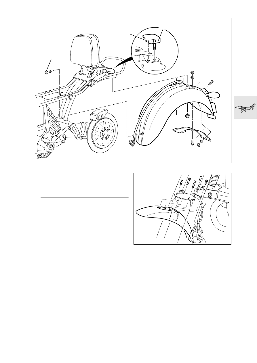
Removing and installing rear
mudguard
•
Take out the front retaining screws (1)
•
Remove the nuts at the rubber cover (2)
e
Caution:
The locking lug (3) of the retaining elements must
engage in the hole.
If necessary, bend the retaining element.
Removing/installing front mudguard
X
Tightening torque:
Mudguard to slider tube bridge ...................... 8 Nm
C460020
1
3
2
CUB0050