BMW AG Motorcycle (R 850 C, R 1200 C). Manual - part 26


  Index      Manuals     BMW AG Motorcycle (R 850 C, R 1200 C). Repair Manual


Search            


Content   ..  24  25  26  27   ..


BMW AG Motorcycle (R 850 C, R 1200 C). Manual - part 26


36.7

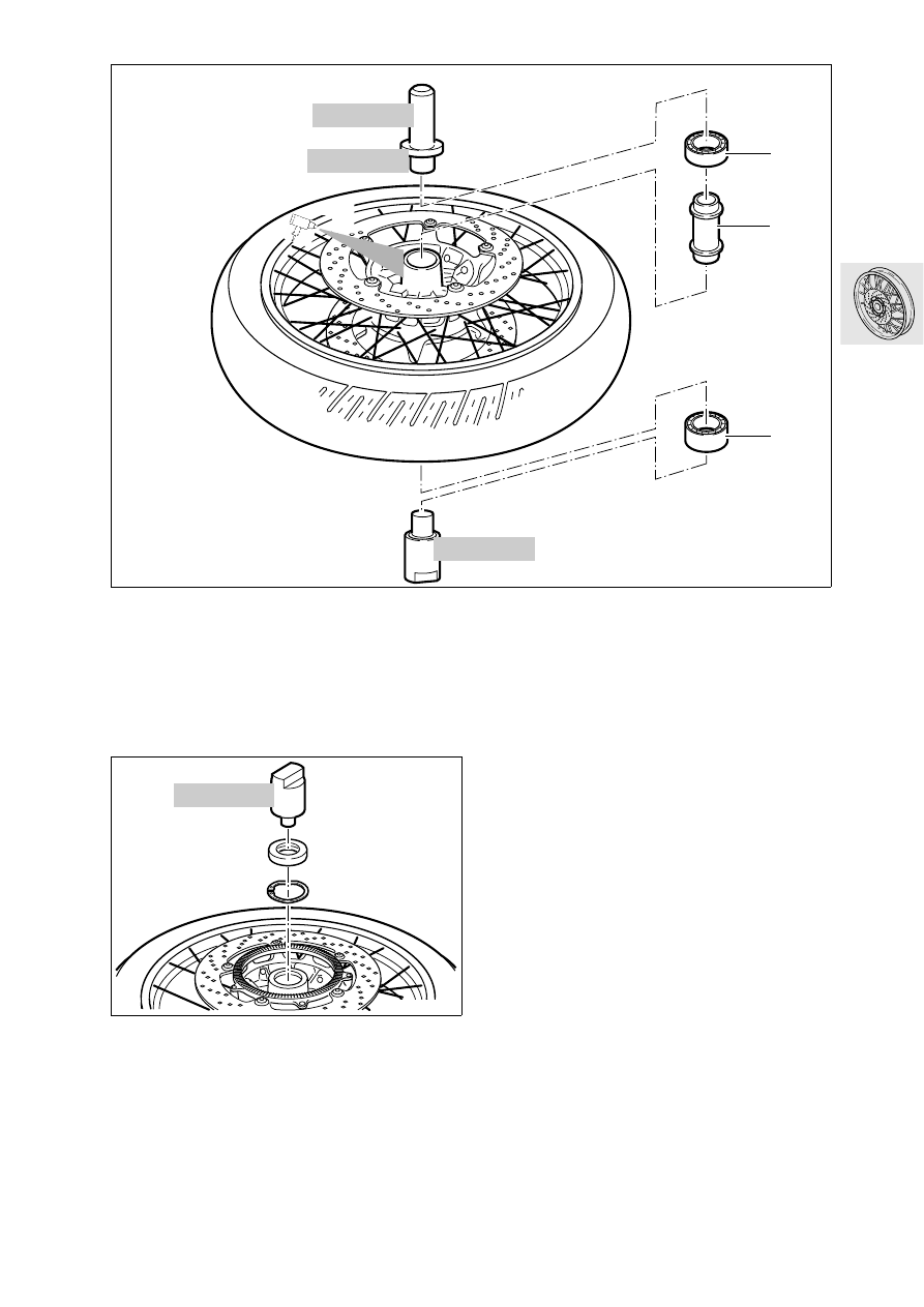
Clamp a drift, BMW No. 36 5 513, into the vice 
and place the wheel on it with the wide bearing (1) 
in contact.

Install spacer tube (2).

Bearing seat temperature 80 °C (176 °F).

Insert narrow bearing (3) with drift,
BMW No. 36 5 512, and handle,
BMW No. 00 5 500.

Install circlip with convex side facing down. 

Drive in shaft sealing ring with drift, 
BMW No. 36 5 513.

36 5 513

C360040

00 5 500

36 5 512

3

2

1

h

100

36 5 513

C360030

36.8

Removing/installing rear wheel

Place the motorcycle on the auxiliary stand, 
BMW No. 00 1 550.

e

 Caution:

Only use wheel studs with length code 60.
Do not oil or grease wheel studs!
Contact faces on rear wheel drive and hub must be 
clean and free of grease.

Tightening torque:

Screw in wheel studs handtight, then
tighten them in a crosswise pattern
Initial tightening ............................................ 50 Nm
Final tightening ........................................... 105 Nm

00 1 550

C360010

36.9

Static balancing of front wheel/rear 
wheel

Install balancing shaft (1), BMW No. 36 3 606
with measuring bushing (2) and nut (3),
BMW No. 36 3 616, in front wheel bearings.

Lightly preload bearing with knurled nut (3).

At the rear wheel, bolt the mounting fixture (4), 
BMW No. 36 3 613, to the centering collar side 
with the balancing shaft.

Align the balancing fixture, BMW No. 36 3 600
with knurled screws and bubble gauge (5/6).

Allow wheel to settle.

Clean points of adhesion for balance weights.

Attach adhesive weights (7) opposite the heavi-
est point on both sides of the wheel rim, with the 
total weight equally divided between the left and 
right sides.

e

 Caution:

Maximum balancing weight 60 g (2.12 oz).

Repeat the balancing procedure as a check.

36 3 600

C360070

36 3 606

36 3 613

36 3 616

36 3 606

36 3 616

36 3 616

2

1

1

4

7

3

6

5

36.10

Checking front/rear wheel rim for 
runout

Remove tyre.

Install the balancing shaft (1), 
BMW No. 36 3 606
, with measuring bushing (2) 
and nut (3), BMW No. 36 3 616, in the front wheel 
bearings.

Lightly preload bearing with knurled nut (3).

Use pin (4) to lock the balancing shaft against the 
balancing stand to prevent the shaft from turn-
ing.

At the rear wheel, attach mounting fixture (5), 
BMW No. 36 3 613, on the centering collar side 
with the wheel studs, then install the balancing 
shaft.

Clamp locating discs (6), BMW No. 36 3 615, to 
the balancing shaft at left and right in such a way 
that the shaft cannot wander.

Align the balancing fixture, BMW No. 36 3 600
with the knurled screws/bubble gauge (7/8).

Check radial/axial runout.

e

 Caution:

Only apply dial gauge to machined inner face of 
wheel rim.

Max. vertical runout/horizontal runout

....................................................  1.3 mm (0.05 in)

C360080

36 3 606

36 3 616

36 3 613

36 3 615

36 3 616

36 3 600

36 3 606

36 3 616

36 3 616

36 3 615

2

1

1

3

8

7

6

6

5

4

36.11

Removing/installing spokes

e

 Caution:

It is not permitted to replace more than one spoke.

Unfasten grub screw (1).

Loosen the spoke nipple/remove the spoke.

Install new spoke.

Center the wheel rim.

Tightening torque:

Spoke nipple ................................................. 5 Nm

Centering the wheel rim

Max. permissible
lateral/vertical runout 
.................. 1.3 mm (0.05 in)
Max. horizontal runout which can
be eliminated by centering 
......... 2.0 mm (0.08 in)

L

 Note:

Vertical runout cannot be compensated for by 
centering the rim.

Centering lateral runout

Determine maximum deviation (plus (+) and mi-
nus (-)).

To center the wheel, the spoke nipples must be 
tightened on the side directly opposite the larg-
est deviation.

Remove grub screw from relevant spoke nipple 
before tightening.

Working forwards and backwards from the max-
imum and minimum value points, take up slack at 
every third spoke nipple.

e

 Caution:

Never attempt to compensate for the entire horizon-
tal runout at only one or two spokes.

At the point where the maximum plus and minus 
values occur, take up slack at 2 spokes.

Four spokes are therefore tightened during each 
centering operation.

Check horizontal runout with a dial gauge.

After every correction of horizontal runout, check 
vertical runout again. 

If necessary, repeat the centering operation.

Lock tightened spokes into place with grub 
screws.

Tightening torque:

Spoke nipple .................................................. 5 Nm
Grub screw .................................................... 1 Nm

C360050

1

GS360090

36.12

46.1

Contents

Page

46

Technical data 

................................................................................................................................3

Removing and installing rear mudguard 

.........................................................................5

Removing/installing front mudguard 

.................................................................................5

Removing and installing front frame 

.................................................................................6

Removing and installing rear frame 

...................................................................................8

Removing/installing footrest supports 

...........................................................................10

Removing and installing side (prop) stand 

...................................................................10

Checking running gear 

............................................................................................................11

Measuring wheel track offset

 ...................................................................................................11

46 Frame

46.3

46

Technical data

R 850 C

R 1200 C

Location of manufacturer’s
type plate / frame number

On frame, at right

Length, overall

mm (in) 2340 (92.1)

Max. height excl. mirrors

mm (in) 1130 (44.5)

Width over mirrors

mm (in) 1050 (41.3)

Width over rider’s footrests

mm (in) 665 (26.2)

Width over pillion footrests

mm (in) 585 (23.0)

Height of seat at unladen weight

mm (in) 740 (29.1)

Wheelbase in normal-load position

mm (in) 1650 (65.0)

Ground clearance at unladen weight

mm (in) 172 (6.77)

Caster angle in normal-load position

mm (in) 86 (3.36)

Steering head angle in normal-load position

° 60.5

Max. wheel track offset

mm (in) 9 (0.35)

Unladen weight, ready for road, full tank

kg (lbs) 256 (564)

Axle load distribution (without rider),
front/rear

kg (lbs) 126/130 (278/287)

Permissible wheel loads

front
rear

kg (lbs)
kg (lbs)

190 (419)
260 (573)

Permitted gross weight

kg (lbs) 450 (992)


Content   ..  24  25  26  27   ..