BMW AG Motorcycle (K1100LT, K1100RS). Manual - part 44
 

  Index      Manuals     BMW AG Motorcycle (K1100LT, K1100RS). Repair Manual


Search            


Content   ..  42  43  44  45   ..


BMW AG Motorcycle (K1100LT, K1100RS). Manual - part 44


62.7

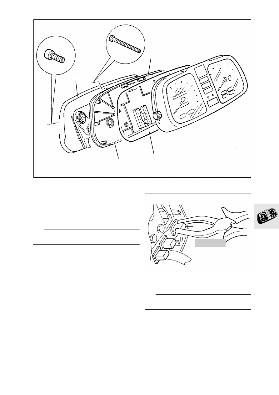
Disassembling and assembling 
instrument cluster

Release instrument support bracket (1).

Release housing cover (2) and remove together 
with gasket (3).

Instrument housing (4).

Assemble in the reverse order of disassembly.

L

 Note:

Ensure gasket is fitted in correct position.

Removing and installing indicator lamp

Grip indicator lamp (1) diagonally with relay pli-
ers, BMW No. 61 1 250, and pull out or press in.

L

 Note:

Do not damage conductor tracks.

LT620030

3

1

4

2

61 1 250

LT620040

1

62.8

Removing and installing p.c. board

Release securing screws and carefully lift out 
p.c. board (1).

L

 Note:

Do not damage p.c. board when removing and 
installing.
Ensure plug contacts are fitted correctly.

Removing and installing quartz clock

Carefully remove frame (1) by pulling upwards.

Carefully press retaining hooks towards the out-
side in the sequence (2,3) and (4,5).

Remove quartz clock (6) by pulling upward.

Install in the reverse order of removal.

Removing and installing frame for indicator 
lamps

Carefully press hooks (arrows) towards the out-
side.

Carefully lift out frame (7,8).

Removing and installing p.c. board for fuel 
gauge

Release screws (1).

Lift out p.c. board (2).

L

 Note:

Do not bend p.c. board while installing.

LT620050

1

LT620060

1

2

6

4

3

5

LT620070

7

8

LT620080

1

2

62.9

Removing and installing revolution counter

Release screws (1).

Lift out revolution counter (2).

Removing and installing speedometer

Release screws (3).

Completely pull out reset button (4) to the right.

Lift out speedometer (5).

LT620090

1

2

LT620100

5

4

3

62.10

Removing and installing p.c. board for gear indi-
cator

Remove tachometer.

Carefully pull pointer (1) off the spindle.

Release screws (2).

Remove dial face (3).

Release screws (4).

Lift out p.c. board (5).

L

 Note:

Note position of spacer (6).

LT620110

2

4

1

3

5

6

63.1

Contents

Page

63

Technical Data

............................................................................................................................... 3

Disassembling and assembling headlights 

....................................................................5

Adjusting headlights 

...................................................................................................................6

63 Lights

63.2

63.3

63

Technical Data

K 1100 LT

K 1100 RS

Lights

Headlight

Halogen rectangular headlight with two-stage 
manual range adjustment

Bulbs

High beam/low beam

H 4 halogen bulb 55/60 W, asymmetric

Parking light

12 V/4 W

Rear light

12 V/10 W

Brake light

12 V/21 W

Turn signal light

12 V/21 W

63.4


Content   ..  42  43  44  45   ..