BMW AG Motorcycle (K1100LT, K1100RS). Manual - part 40
 

  Index      Manuals     BMW AG Motorcycle (K1100LT, K1100RS). Repair Manual


Search            


Content   ..  38  39  40  41   ..


BMW AG Motorcycle (K1100LT, K1100RS). Manual - part 40


46.21

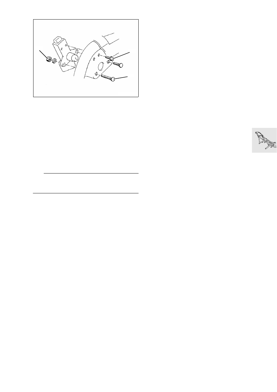
Removing and installing seat lock

1. Saucer-head screw
2. Phillips-head screw
3. Stop nut

Removing and installing handle

Lever out spring using screwdriver, remove 
spring seat.

Detach handle.

Remove spring with second spring seat.

Install in the reverse order of removal.

L

 Note:

Grease the pivot point a little before installing han-
dle. Spring seats must engage in the grooves.

LT510040

2

1

3

46.22

Installing frame

Installation basically takes place in the reverse 
order of removal.

Place frame on drive train and firmly tighten 
screws and bolts in the specified order.

1. Screw in all 5 screws loosely, i.e. not as far as 

they will go. Fit a 1 mm thick spacer ring, inner 
support ring at the front right between the cylin-
der head and frame strut.

2. Firmly tighten screws 1,4 and 3.
3. Measure distance at front left and fit outer sup-

port ring, firmly tighten screws.

4. Measure distance of mounting point on interme-

diate flange and firmly tighten screw.

Tightening torque:

Frame to engine ........................................... 45 Nm

Install telescopic fork and adjust steering.

Setting torque:
Hexagon nut................................................  12 Nm

New bearing adjustement procedure:
Pre-tighten hexagon nut to........................... 25 Nm
Move steering from stop to stop several times, 
loosen hexagon nuts, retighten .................... 12 Nm

Tightening torques:

Locking tube ................................................ 65 Nm
Hexagon nut ................................................ 65 Nm
Clamping screws of fork bridge.................... 15 Nm
Clamping block for handlebar ...................... 22 Nm

Setting dimensions:
Clutch play at handlebar 
lever ....................... 4 ± 0,5 mm (0.157 ± 0.0197 in)
Cable length at clutch release 
lever ............................ 75 ± 1 mm (2.953 ± 0.04 in)
Accelerator cable play............. 0,75 mm (0.0295 in)

Carefully fill and bleed brake system

Tightening torques:

Brake line to handbrake cylinder .................. 11 Nm
Brake line to distributor ................................ 11 Nm
Brake line to brake caliper.............................. 7 Nm
Bleed screw ................................................... 7 Nm
[ABS II] Pressure modulator to holder ......... 17 Nm

LT460300

2

3

4

1

5

46.23

Removing and installing main centre 
stand

[RS] 

Remove lower section of fairing

.

Raise motorcycle with lifting gear, 
BMW No. 00 1 510, under the oil sump until 
stand is free to move.

Disconnect cable clips for side stand line.

Release retaining screws (1) and detach main 
stand together with side stand.

Install in the reverse order of removal.

L

 Note:

The retaining screws are micro-encapsulated and 
can therefore not be re-used. Clean thread and 
holes. Fit screws with Loctite 243.

Line arrangement for side stand

Tightening torque:

Main stand to bearing block ......................... 41 Nm

LT460310

1

00 1 510

LT460320

LT460330

46.24

Disassembling and assembling side 
stand

D

isassembling side stand

Detach switch (1).

Detach tension springs (2).

Remove bracket (3) with spring.

Remove operating hook (4).

Remove leg spring (5).

Release securing screw (6) of side stand.

LT460340

1

2

6

4

5

3

46.25

Assembling side stand

L

 Note:

The securing screw of the side support is micro-en-
capsulated and cannot be reused. Clean thread and 
holes. Coat screws with Loctite 243 before insert-
ing.

Fit securing screw (6) with Loctite 243.

Fit leg spring (1) as illustrated.

Install operating hook (2) and bracket (3), note in-
stallation position (arrow).

e

 Caution:

Do not grease operating hook and bracket, 
increased dirt accumulation!

Attach tension springs (4).

Prior to installation, check condition of switch, 
contact spring must not be bent.

In no-load condition, there must be an air gap 
(clearance) between the contact spring (1) and 
contact point on the switch.

Secure switch with 2 O-rings (2) on the retaining 
screws for the bearing block.

Install stand with side stand.

Tightening torque:

Side stand to bearing block ......................... 41 Nm

LT460350

2

4

3

1

LT460360

2

1

46.26

Disassembling and assembling main 
centre stand 

Detach tension springs (1).

Release screws (2) on left/right.

Release retaining ring (3).

Press out sleeve (4) on left/right.

Remove bearing block (5).

Loosen grease nipple (6).

Assemble in the reverse order of disassembly.

L

 Note:

Screws (2) are micro-encapsulated and must there-
fore not be re-used. Clean threades and holes and 
fit screws with Loctite 243.
Lubricate sleeves with SHELL RETINAX A.

LT460370

1

6

5

1

2

3

4

46.27

Checking switching function of side 
stand

Set vehicle on centre stand on even base or lift-
ing platform.

Spray switching kinematics of side stand with 
quick-action cleaner and fold out and in several 
times.

Completely fold out side stand and mark position 
on the base.

Make a second marking at the distance ”a” and 
a third marking at the distance ”b”.

Distances:
”a” .................................................. 95 mm (3.74 in)
”b” .................................................. 50 mm (1.97 in)

Fold in side stand and start engine.

Slowly fold out side stand, the engine must cut 
out in the area of dimension ”b”.

If the engine does not cut out, check or replace 
the switch.

e

 Caution:

Bending the contact spring can cause switch mal-
functions.
Therefore:
Never bend the contact spring!

Operate starter while slowly folding in side stand, 
the engine must start up in area ”b”.

If the engine does not start up, or if the side stand 
is difficult to move, check the switch or disas-
semble the side stand.

LT460380

a

b

46.28


Content   ..  38  39  40  41   ..