BMW AG Motorcycle (K1100LT, K1100RS). Manual - part 39
 

  Index      Manuals     BMW AG Motorcycle (K1100LT, K1100RS). Repair Manual


Search            


Content   ..  37  38  39  40   ..


BMW AG Motorcycle (K1100LT, K1100RS). Manual - part 39


46.13

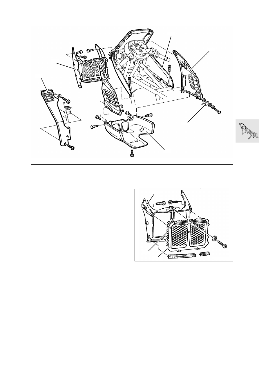
Removing and installing fairing [RS]

Removing and installing lower section 
of fairing

Lower section of fairing (1)

Release securing element on side section (2).

Release securing screw at oil sump.

Install in the reverse order of removal.

Removing and installing side section 
of fairing

Side section of fairing (2)

Remove lower section of fairing (1).

Remove knee pad (3).

Release securing screw on upper section (4), on 
radiator cowling (5) and on bracket (6).

Install in the reverse order of removal.

Removing and installing radiator 
cowling

Radiator cowling (5)

1. Frame
2. Grille
3. Cowling

LT460140

6

4

2

5

1

3

LT460150

2

3

1

46.14

Removing and installing upper 
section of fairing

Remove lower section of fairing, side sections 
and radiator cowling.

Remove cover (1).

Remove support bracket (2).

Remove cover at right/left (3) and centre (4).

Disconnect plug connection for turn signal indi-
cator and headlamp.

Release securing screw (5) on frame and (6) at 
fairing support bracket.

Remove fairing by pulling forward.

Install in the reverse order of removal.

Removing and installing windshield, 
spoiler and headlamp

1. Spoiler
2. Windshield
3. Headlamp

LT460160

3

6

1

2

1

5

2

4

LT460170

1

3

2

46.15

Removing and installing fairing 
support bracket

Remove fairing.

[LT] Remove instrument cluster.

Remove horns (1).

Disconnect cable clips for wiring loom.

Release securing screw (2).

Install in the reverse order of removal.

Arrangement of cable clips [LT]

Arrangement of cable clips [RS]

Tightening torque:

Fairing support bracket to frame .................... 9 Nm

LT460200

1

2

LT460190

LT460200

46.16

Checking running gear

Measuring track offset

Mount motorcycle on centre stand on even base.

Position track offset gauge (1), 
BMW No. 36 3 920, on left or right side of motor-
cycle.

L

 Note:

In order to measure with the track offset gauge from 
the left or right side, the supports need only be 
screwed in from the other side.

Adjust supports (2) so that the measuring level is 
as near as possible to the centre of the wheel. It 
must be possible to smoothly slide the gauge to-
wards the motorcycle.

Adjust limit stops (arrows) so that they only rest 
on the rim and not on the tyre.

Attach hook (3) to wheel spoke and firmly pull 
gauge up to the wheel.

Align front wheel parallel with respect to the 
gauge.

Measure distance with depth gauge or straight 
edge from outer edge of gauge to rim and note 
down measurement.

LT460210

2

3

36 3 920

1

46.17

Calculate track offset ”S”:

EXAMPLE:

The track offset ”S” represents the amount by 
which the longitudinal axis of the front wheel is 
offset to the left or right with respect to the rear 
wheel.

Permissible track offset:
S .................................................................. 12 mm

L

 Note:

Significance of measurement result:
Negative sign = Track offset to left
Positive sign = Track offset to right

Formula:

S = 

 – 

Fixed value „A“
(length of measuring stops)

A = 50,0 mm

half of rear wheel rim width

 = 44,5 mm

Measured value „B“

B = 52,0 mm

half of front wheel rim width

 = 41,0 mm

Track offset „S“

S = 

 – 

S = 94,5 mm – 93,0 mm

Track offset „S“ = 1,5 mm

LT460220

1

B

A

B

A

S

F

v

F

h

A

F

h

2

-----

+

B

F

v

2

----

+

F

h

2

-----

F

v

2

----

A

F

h

2

-----

+

B

F

v

2

----

+

46.18

Checking frame with gauge

Remove fairing.

Support motor cycle with lifting gear, 
BMW No. 00 1 510.

Remove telescopic fork.

Outer bearing race at top and bottom remain in 
steering head.

[RS] Remove left and right footrest plate.

Release frame securing screw at gearbox.

L

 Note:

After releasing the frame securing screw at the gear-
box, check that the screws can be screwed in again 
easily.
If this is not possible, the frame is in all probability 
distorted.

Fit adapter, BMW No. 46 5 606, instead of se-
curing screws.

Screw measuring discs, BMW No. 46 5 603, at 
the same level on the adapter.

Connect frame test gauge (1), 
BMW No. 46 5 600,at bottom of steering head 
and clamp together frame and gauge with spin-
dle (2), BMW No. 46 5 604, and crank (3).

LT460230

2

3

46 5 600

1

46.19

Fit measuring pins (1), BMW No. 46 5 602, lightly 
greased, in the outer holes.

Slightly loosen nut on steering head and align 
gauge so that the same distance is obtained on 
the left and right with respect to the measuring 
discs.

L

 Note:

The frame is in order when the tips of the measuring 
pins on the left and right are located in approximate-
ly the same position within the grid circle.

Max. deviation:

Left to right

................... 2 mm (0.0787 in) = 2 

boxes

e

 Caution:

The frame must be replaced if the deviation is great-
er than the permissible tolerance.
Straightening the frame of the K model is not ap-
proved by the manufacturer.

LT460250

46 5 602

46 5 602

46.20

Removing and installing frame

Removing frame

Set motorcycle on centre stand.

Support with lifting gear, BMW No. 00 1 510, un-
der oil sump. 

Remove seat.

Remove rear section.

Remove rear mudguard.

Remove fuel tank.

Remove fairing complete.

Remove fairing support bracket.

Remove radiator.

Drain the brake system.

Release brake line at hand brake cylinder, close 
off line and brake fluid reservoir.

Remove handlebar with multifunction switches, 
detach cables.

Remove telescopic fork complete with front 
wheel.

Remove rear protective plate with coolant reser-
voir.

Remove Motronic control unit.

[ABS I] Remove ABS  control unit.

Remove battery.

[ABS I] Remove ABS pressure modulators.

[ABS I] Remove ABS brake line, front pressure 
modulator.

Remove footrest plates.

[ABS II] Detach front brake lines at ABS unit.

Remove spring strut.

Release frame at engine and lift off.

Remove frame wiring loom with central electrics 
box.

[ABS II] Remove front brake lines.

Dismantle/assemble frame.

Disassembling and assembling frame

Remove all rubber mounts and cage nuts on 
frame.

Removing outer bearing race in steering head

Remove outer bearing race (1) at top and bottom 
with inner extractor, BMW No. 00 5 560 in con-
junction with support ring, BMW No. 31 4 800.

e

 Caution:

Bearing and outer bearing race belong together, do 
not interchange and only renew together!

Installing outer bearing race in steering head

Fit outer bearing race (1) top/bottom with spin-
dle, BMW No. 46 5 604, from frame test gauge, 
BMW No. 46 5 600, and spacer, 
BMW No. 31 4 820, with washer and hexagon 
nut (2).

L

 Note:

If a bearing shell has been removed, immediately in-
stall the new shell otherwise there will be no guide 
for the second bearing shell.

00 1 510

LT460320

00 8 560

LT460270

1

31 4 800

46 5 604

LT460280

31 4 820

2

1


Content   ..  37  38  39  40   ..