BMW AG Motorcycle (K1100LT, K1100RS). Manual - part 34
 

  Index      Manuals     BMW AG Motorcycle (K1100LT, K1100RS). Repair Manual


Search            


Content   ..  32  33  34  35   ..


BMW AG Motorcycle (K1100LT, K1100RS). Manual - part 34


34.17

Removing and installing pressure 
modulator

e

 Caution:

Work on the ABS unit is only to be carried out by an 
authorised BMW workshop.

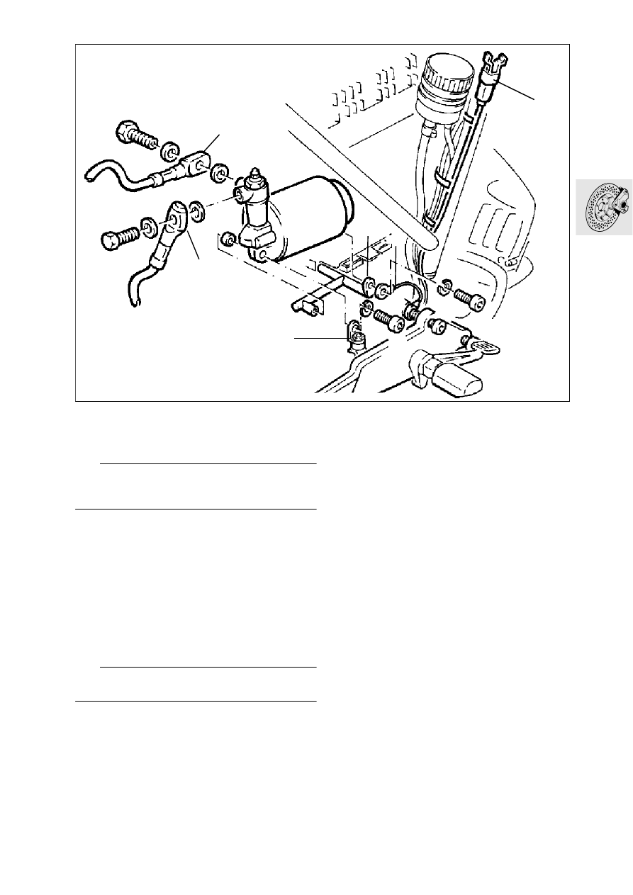
[ABS I] Removing and installing front 
or rear pressure modulator

Remove the fuel tank.

Separate plug connector (1) (blue) for the pres 
sure modulator.

Clean the hydraulic pump assembly and the 
brake lines.

Detach brake lines (2/3) at the pressure modula-
tor and seal/cover them.

e

 Caution:

Escaping brake fluid will damage painted surfaces.

Detach the pressure modulator at silentbloc 
mount (4) and at the holder.

Note earth (ground) wire (6).

Install in the reverse order of work.

Restore the correct brake fluide level and bleed 
the brake system.

X

 Tightening torques:

Pressure modulator to holder ....................... 17 Nm
Brake line ..................................................... 18 Nm

LT340130

1

2

3

4

5

6

34.18

[ABS II] Removing ABS unit

Remove the dualseat.

Remove the left and right battery trim panels.

Remove the Motronic control unit.

Remove the battery.

Remove the coolant level equalising tank.

Take off the lower section of the front mudguard.

Drain the front and rear brake circuits.

e

 Caution:

Escaping brake fluid causes damage to painted sur-
faces.

Detach ABS brake lines (1) from the ABS unit.

e

 Caution:

To avoid leaks caused by particles of dirt penetrat 
ing the brake system, clean the hydraulic pump as 
sembly and the brake lines before detaching them. 
If appropriate, cover or seal the line unions.

Secure the front brake lever to the handlebar 
with a rubber band (so that the fluid replenishing 
bore is close).

Release cover (2) on the pressure modulator with 
a suitable centre punche or screwdriver, and pull 
off upwards.

Detach the lines.

Pull off 2-pin plug (4).

Pull off central plug (5).

Remove ABS unit (6).

LT340250

6

1

5

2

3

4

34.19

[ABS II] Installing ABS unit

Install ABS unit (6).

Reconnect central plug (5).

e

 Caution:

Do not tilt the cables or the insulation may be dam-
aged.

Push 2-pin plug (4) on correvtly and as far as it 
will do, then press the two wires into the centre 
(smal ler) cable entries.

Attach both plugs of the connecting cable/wiring 
harness to the threaded pins with the crimp fac-
ing forwards.

Press the cables into the remaining cable guides.

Tighten the nuts.

e

 Caution:

Use new self-locking nuts.

X

 Tightening torques:

Battery –/M5................................................ 3.5 Nm
Battery  +/M5 ................................................. 3 Nm

Fit a new cover.

e

 Caution:

When sliding on, make sure that all cables are posi-
tioned correctly in their guides. 
Always use a new cover.
The old cover must be scrapped.

Screw ABS brake lines (1) firmly to the ABS unit.

Fill/bleed the brake system.

Install the coolant level equalising tank.

Install the battery.

Install the Motronic control unit.

Install the battery covers.

Install the fuel tank.

X

 Tightening torques:

ABS unit to mounting
M6 screw ....................................................... 9 Nm
Brake line to ABS unit .................................. 18 Nm
Bleed screw at ABS unit................................. 9 Nm

34.20

[ABS II] Removing and installing 
relay and relay base

[ABS II] Removing relay

e

 Caution:

Switch off the ignition and disconnect and insulate 
the earth (ground) lead.

Remove cover (1) from ABS control unit, press 
the catch in with a screwdriver and pull the cover 
off upwards.

Cover (1) must be scrapped.

Disconnect wires (2) and scrap the retaining 
nuts.

e

 Caution:

Do not tilt the cables or the insulation may be dam-
aged.

Pull off the 2-pin plug.

Take out relay base (4).

Loosen the screws at the relay base by app. 2 
turns with a Torx T20 screwdriver.

Pull the relay off upwards.

[ABS II] Installing relay

Insert ABS relay with FAG logo in the direction of 
the retaining hook.

Tighten the screws at the relay base.

Push the relay base into the relay housing, at the 
same time pressing both engine wires into the 
left relay housing cable guide (red at bottom, 
black at top).

Attach black cable to left threaded pin (M5) with 
the crimp facing to the rear.

e

 Caution:

Do not tilt the cable or the insulation may be dam-
aged.

Push the 2-pin plug fully on in the correct posi-
tion and press the two wires into the centre 
(smaller) cable guides.

Attach both connecting lead/wiring harness 
plugs to the threaded pins with the crimp facing 
forwards.

Press both leads into the remaining cable 
guides.

Tighten the nuts.

e

 Caution:

Always use new self-locking nuts.

LT340270

1

3

2

4

34.21

Install a new cover (1).

e

 Caution:

When pushing on, make sur that all cables are cor-
rectly located in their guides. 
Scrap the old cover.

[ABS II] Removing relay base

e

 Caution:

Switch off the ignition and disconnect and insulate 
the earth (ground) lead.

Remove cover (1) from ABS control unit, press in 
the catch with a screwdriver and pull the cover 
off upwards.

Scrap the cover.

Disconnect leads (2) and scrap the nuts.

e

 Caution:

Do not tilt the cables or the insultation may be dam-
aged.

Pull off the 2-pin plug.

Take out relay base (4).

Take out screws on relay base with a Torx T20 
screwdriver
.

Remove the ABS relay

Press the contact lock out of the relay base.

Using the special tool, Article No. 50000-017-
507 from the Grote und Hartmann company

insert the plug from the relay side.

e

 Caution:

The contact has a double locking action. 
When pulling the plug out of the relay base, do not 
exert too much tension on the cable. 
If the cable breaks off, the complete ABS will have 
to be renewed.

[ABS II] Installing relay base

Ben up the contact lock for the plug.

Insert the contact into the relay base.

e

 Caution:

The contact must be heard to engage, and must be 
firmly seated.

Insert ABS relay with FAG logo in the direction of 
the retaining hook.

Insert one Torx screw into the ring cable shoe on 
the red engine lead.

L

 Note:

The crimp side must face toward the screw head.

e

 Caution:

The same Torx screws must be used because of 
their self-locking acition. When inserting, make sure 
that the thread already present in the sheet metal is 
entered again. 
Failing this, the screws could come loose when ex 
posed to vibration.

Place the ring cable shoe (with two leads) on the 
hole in the insert on the rear of the relay base, 
with the crimped side facing the relay base, and 
screw on together with the red engine lead, us-
ing a Torx screw. 

With the second Torx screw, attach the flat plug 
to the relay.

Press the contact lock into the relay base at the 
side.

Push the relay base into the relay housing and at 
the same time press both engine leads into the 
left cable guide on the relay housing (red at bot-
tom, black at top).

Place the black engine lead on the left threaded 
pin (M5) with the crimp facing to the rear.

e

 Caution:

Do not tilt the cable, or the insulation may be dam-
aged.

Attach the 2-pin plug in the correct position and 
push on as far as it will go, at the same time 
pressing the two leads into the centre (smaller) 
cable guides.

Place both plugs of the connecting lead/wiring 
harness on to the threaded pins with the crimp 
facing forwards.

Press both leads into the remaining unoccupied 
cable guides.

Tighten the nuts.

e

 Caution:

Always use new self-locking nuts.

Install a new cover (1).

e

 Caution:

When sliding into position, make sure that all cables 
are in the correct guides.

34.22

Removing and installing rear brake 
caliper

Drain brake System.

Release bottom of suspension strut (1).

Detach suspensions strut from stud bolt.

Release brake line at brake caliper.

Disconnect ABS plug connection for sensor line.

Release brake caliper and carefully lift out.

Install in the reverse order of removal.

L

 Note:

Replace sealing rings of brake lines.

e

 Caution:

Ensure brake fluid does not come in contact with 
painted parts of vehicle; brake fluid destroys the 
paintwork.
Check ABS sensor spacing, if necessary readjust 
with spacer plates.

Sensor spacing rear:
Up to 1996 MY  .............................. 0.60 - 0.65 mm 

................................................ (0.0236...0.0256 in)

From 1997 MY on .......................... 0.45 - 0.55 mm

................................................ (0.0177...0.0216 in) 

Removing and installing rear brake 
pads

Remove cap (2).

With the aid of a drift, drive out retaining pins (3) 
from the wheel side.

Remove brake pads by pulling upward.

Install in the reverse order of removal.

Minimum brake pad thickness .................... 1.5 mm

L

 Note:

Before installing the new brake pads, press back 
pinion in brake caliper with the aid of the piston re-
setting tool (4), BMW No. 34 1 500.

e

 Caution:

Carefully bleed brake system!

LT340140

1

3

2

34 1 500

LT340040

4

34.23

Dismantling and assembling rear 
brake caliper

Dismantling rear brake caliper

Remove keepers (1).

Drive out spring (2) and retaining pin (3). 

Take out brake pads.

Seal the bleed screw.

Tightening torque:

Bleed screw at brake caliper rear ................. 11 Nm

Remove sealing rings (4) from left/right cylinder.

e

 Caution:

Keep fingers away from gap between pistons and 
side contact face of brake pads; risk of injury! 
If necessary press back with screwdriver carefully.

Hold a cloth over the brake caliper piston.

Carefully press out brake piston (6) with a com-
pressed air gun applied to the connecting bore; 
work at low air pressure.

Remove sealing rings (5) from left/right cylinder 
hole.

Assembling rear brake caliper

Coat the new sealing rings with brake fluid and 
insert them into the left/right brake caliper cylin-
ders.

e

 Caution:

Do not tilt the brake pistons when installing.

Coat both brake caliper pistons with brake fluid 
and install them.

L

 Note:

The installed position must be correct!

Insert brake pads and secure with retainers.

LT340290

2

1

3

4

6

6

5

5

34.24

Removing and installing rear brake 
disc

Remove brake caliper.

Remove rear wheel.

Remove brake disc.

L

 Note:

Mark installation position of the brake disc so that 
the vertical runout of the pulse wheel is not 
changed.

Install in the reverse order of removal.

L

 Note:

Screw in retaining screws with Loctite 270
Check ABS sensor spacing, if necessary adjust with 
spacer plates.

X

 Tightening torque:

Brake disc carrier ......................................... 21 Nm

e

 Caution:

ABS - The vertical runout must be determined if the 
brake disc and therefore also the pulse wheel are re-
placed.

LT340150


Content   ..  32  33  34  35   ..