BMW AG Motorcycle (K1100LT, K1100RS). Manual - part 33
 

  Index      Manuals     BMW AG Motorcycle (K1100LT, K1100RS). Repair Manual


Search            


Content   ..  31  32  33  34   ..


BMW AG Motorcycle (K1100LT, K1100RS). Manual - part 33


34.9

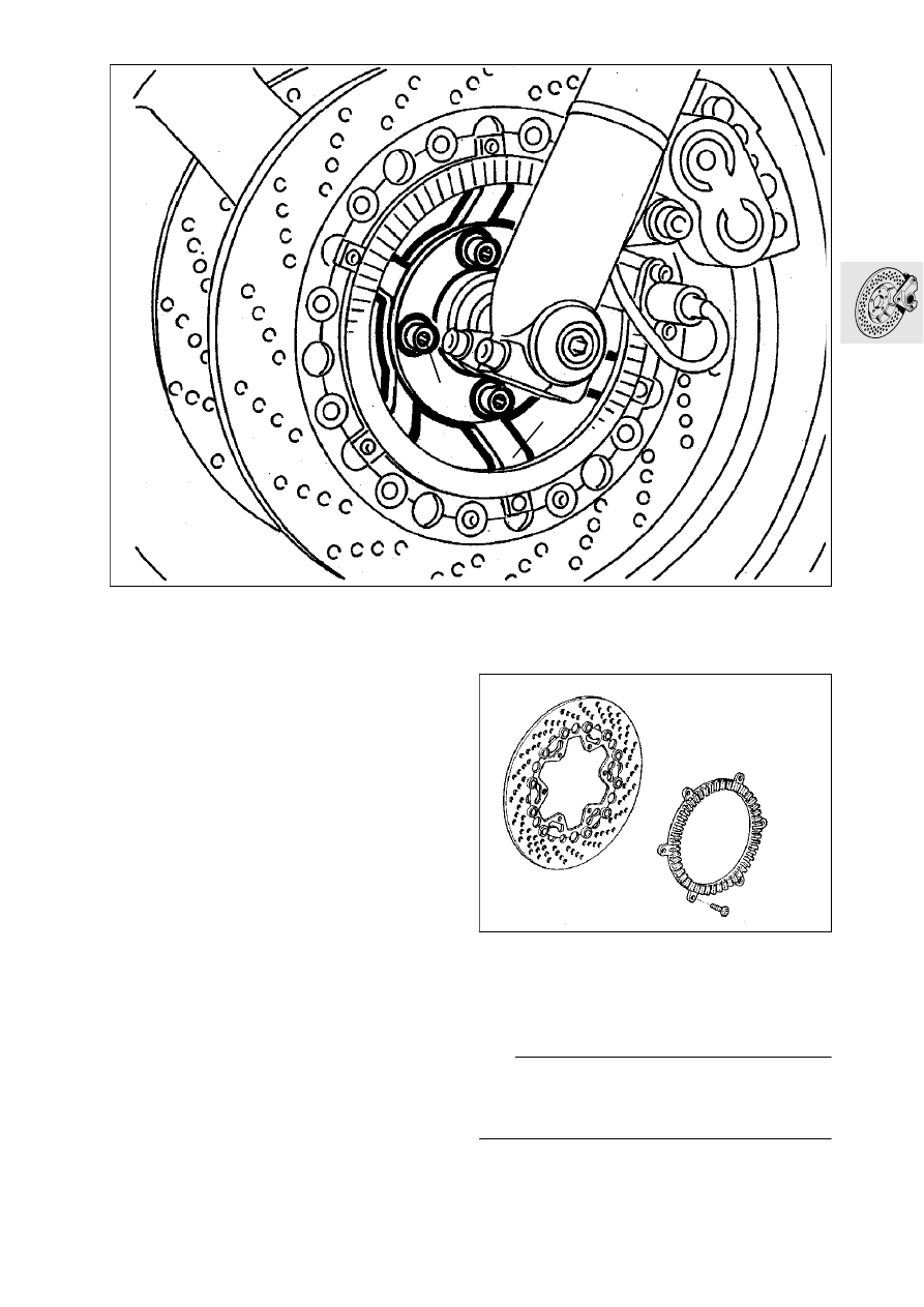
Removing and installing front brake 
disc

Remove front wheel.

Release retaining screws (1) for brake disc carri-
er.

Detach brake disc carrier (2) with brake disc.

Removing and installing ABS pulse 
wheel

Release pulse wheel on brake disc carrier.

X

 Tightening torque:

Pulse wheel.................................................... 4 Nm

L

 Note:

Before installing the pulse wheel, clean the micro-
encapsulated screws and secure them with, for ex-
ample, Loctite 2701.

LT340050

1

2

LT340060

34.10

Removing and installing front ABS 
sensor

Remove fuel tank.

Disconnect plug connection (1) of sensor line.

Remove cover for brake distributor.

Remove rear section of mudguard.

Detach cable clips.

Release sensor (2) with Torx socket, 
BMW No. 34 2 500.

Install in the reverse order of removal.

L

 Note:

Carefully install the sensor line (arrow), note position 
and number of cable clips and ensure tyre can turn 
smoothly.
Check sensor spacing where the gap is largest; if 
necessary readjust with spacer plate (3).

Sensor spacing
Up to 1996 MY............................... 0.50 - 0.55 mm
From 1997 MY ............................... 0.45 - 0.55 mm

X

 Tightening torque:

Sensor to fork slider tube ..............................  4 Nm

LT340070

1

3

2

34.11

Adjusting front ABS sensor gap

Raise front wheel with front wheel stand, 
BMW No. 36 3 950.

Secure dial gauge holder (1), BMW No. 34 2 520 
with dial gauge to fork sliding tube.

Secure measuring shoe (2), BMW No. 34 2 510 
to feeler of dial gauge.

Set dial gauge at marking (arrow) on pulse wheel 
to zero.

Measure axial runout over the entire circumfe 
rence.

Adjust the sensor spacing with spacer plates at 
the point with the least pointer deflection.

Remove and install sensor using Torx socket, 
BMW No 34 2 500.

Sensor spacing front:
Up to 1996 MY  .............................. 0.50 - 0.55 mm 

................................................ (0.0197...0.0216 in)

From 1997 MY on .......................... 0.45 - 0.55 mm 

................................................ (0.0177...0.0216 in)

e

 Caution:

After adjustment, check that the sensor is clear over 
the entire circumference.

L

 Note:

If the pulse wheel has been replaced, its maximum 
axial runout must be determined; mark point with 
coloured dot.

LT340080

1

2

34 2 520

34 2 510

34.12

Removing and installing front brake 
line

Removing upper brake line

Drain brake system.

Remove fuel tank.

Release brake line (1) at handbrake cylinder.

Remove cover for brake distributor on mud-
guard.

Release brake line at the distributor.

Install in the reverse order of removal.

L

 Note:

Secure brake line to handbrake cylinder such that it 
does not chafe or kink when the handlebar is turned. 
Replace sealing rings of brake lines.

e

 Caution:

Ensure brake fluid does not come in contact with 
painted parts of the vehicle; brake fluid destroys the 
paintwork.

Removing lower brake line

Remove rear section of mudguard.

Release brake line at distributor and at the brake 
caliper.

Install in the reverse order of removal.

L

 Note:

Replace sealing rings of the brake lines.

Carefully bleed brake system.

X

 Tightening torques:

Brake line to handbrake cylinder .................. 18 Nm
Brake line to distributor ................................ 18 Nm
Brake line to brake caliper............................ 18 Nm
Bleed screw ................................................. 14 Nm

LT340090

1

LT340100

34.13

Removing and installing ABS brake 
line from front pressure modulator

Remove knee pads.

Remove fuel tank.

Release screw connections (1,2).

Release connections at pressure modulator (3).

Remove both lines together.

Release spacer (4) and replace defective line.

Install the reverse order of removal.

X

 Tightening torques:

Screw connection ........................................ 18 Nm
Line to pressure modulator .......................... 18 Nm

LT340110

1

2

3

4

34.14

Removing and installing handbrake 
cylinder

Drain brake system.

e

 Caution:

Ensure brake fluid does not come in contact with 
painted parts of the vehicle; brake fluid destroys the 
paintwork.

Remove cover (1).

Remove mounting pin (2) for handbrake lever.

L

 Note:

The mounting pin is secured with Tuflok - blue. This 
screw fitting can be released and retightened sever-
al times.

Carefully detach sealing sleeve (3).

Press piston (3) a little way inward.

Release stop screw (4).

e

 Caution:

Piston is under spring loading.

Relieve load on piston and remove together with 
spring (5).

Check brake cylinder, piston and sealing rings.

Install in the reverse order of removal.

L

 Note:

The sealing lips of the piston must face inwarde. 
Lightly grease thrust pin on handlebar lever with 
Shell Retinax A“ or similar.
Firmly tighten mounting pin (2) to specified torque.
Coat stop screw (1) with Loctite 270 and screw in 
until handlebar lever is free of play, then turn by a 
further half turn.
Seal screw head with paint.

X

 Tightening torque:

Mounting  pin ................................................. 8 Nm

LT340120

1

2

4

3

5

34.15

Bleeding brake

e

 Caution:

Escarping brake fluid can damage painted surfaces.

Bleeding front brake

Bleeding brake caliper

Remove front brake pads.

e

 Caution:

Do not tilt the brake caliper when removing or install-
ing. 
The brake disc could be damaged.

Detach the cover from the brake fluid reservoir 
and remove it together with the diaphragm.

Add brake fluid.

e

 Caution:

When bleeding, brake fluid level must not be al 
lowed to drop below the -MIN“ mark, or else air will 
be drawn into the brake circuit.
If this happens, the bleeding procedure must be re 
peated.

Connect a vessel to the brake caliper bleed 
screws to trap escaping brake fluid, then open 
the bleed screw by half a turn.

Use piston resetting tool, BMW No. 34 1 500, to 
press the brake piston fully back.

Take out the piston resetting tool, insert spacer, 
BMW No. 34 1 520, and move it up to the brake 
disc.

Press the piston back in the second brake cali-
per, but do not remove the piston resetting tool.

Close the bleed screw.

Pull in the handbrake lever several times until 
brake pressure is felt to build up.

Maintain pressure at the handbrake lever and 
open the bleed screw, at the same time pulling 
the handbrake lever im firmly.

e

 Caution:

Do not release the handbrake lever until the bleed 
screw has been closed.

Close the bleed screw, then release the hand 
brake lever.

Allow the brake fluid to emerge from both brake 
calipers until it is clear and free from bubbles.

Close the bleed screws.

Remove the spacer and the piston resetting tool.

Install the brake pads/brake calipers.

X

 Tightening torque:

Brake caliper to slider tube .......................... 40 Nm

LT340040

34 1 500

LT340230

34 1 520

34.16

[ABS II] Bleeding pressure modulator

Remove the left battery cover.

Connect a vessel to the brake caliper bleed 
screws to trap escaping brake fluid, then open 
the bleed screw by half a turn.

Maintain pressue at the handbrake lever and 
open the bleed screw, at the same time pulling 
the hand brake lever in firmly.

e

 Caution:

Do not release the handbrake lever until the bleed 
screw has been closed.

Allow the brake fluid to emerge from both brake 
calipers until it is clear and free from bubbles.

Close the bleed screw while keeping the hand 
brake lever pulled in.

Bleeding the handlebar fitting

Remove combined switch (1) from the right han-
dlebar fitting.

Remove clamping screw from handlebar fitting.

Turn the brake flulid reservoir up round the han-
dle bar (arrow) until the air escapes from the 
brake line.

Turn the reservoir back down.

Tighten the clamping screw on the handlebar fit 
ting.

L

 Note:

When adding brake fluid, note the thickness of the 
brake pads. Add brake fluid up to the -MAX“ mark if 
the pads are new.

Add brake fluide.

L

 Note:

When checking front brake fluid level, the brake fluid 
reservoir must always be in a horizontal posi tion.

Replace the diaphragm and reservoir cover in po 
sition.

Tighten the retaining screws without using force.

Check brake operation.

Install the combined switch.

Bleeding rear brake

Bleeding brake caliper

The rear brake caliper does not have to be remo 
ved, nor the pistions pressed back.

The remaining procedure is the same as when 
bleeding the front brake circuit.

X

 Tightening torque:

Brake caliper to rear wheel drive .................. 40 Nm

[ABS II] Bleeding pressure modulator

Follow the same procedure as when bleeding the 
front brake circuit.

L

 Note:

When adding brake fluid, note brake pad thickness. 
Add brake fluid up to the „MAX“ mark with new pads.

Add brake fluid.

Replace the diaphragm and reservoir cover in 
position.

Check that the brake is operating correctly.

LT340310

1

LT340260

MAX

MIN


Content   ..  31  32  33  34   ..