BMW AG Motorcycle (K1100LT, K1100RS). Manual - part 29
 

  Index      Manuals     BMW AG Motorcycle (K1100LT, K1100RS). Repair Manual


Search            


Content   ..  27  28  29  30   ..


BMW AG Motorcycle (K1100LT, K1100RS). Manual - part 29


32.13

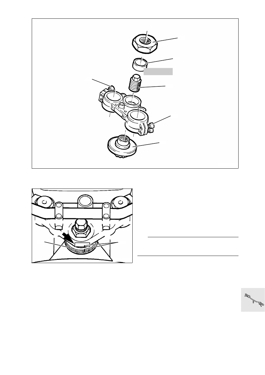
Adjusting steering bearing play

Fit a piece of adhesive tape (arrow) on the fork 
bridge above the setting ring.

Mark current position of setting ring (1) on adhe-
sive tape and on setting ring (2).

Slide thrust ring (3), BMW No. 31 4 890, over the 
locking tube (4).

Lock thrust ring with hexagon nut (5) while hold-
ing the locking tube.

Using the hexagon nut, turn back the setting ring 
a little then tighten to the specified setting 
torque.

Setting torque:

Hexagon nut ................................................. 12 Nm

Setting torque for new bearing:
Pretighten hexagon nut to ............................ 25 Nm
Move steering from lock to lock several times, 
loosen hexagon nut and retighten ................ 12 Nm

Mark new position of setting ring on adhesive 
tape.

Release hexagon nut and remove thrust ring.

Firmly tighten locking tube, tighten hexagon nut.

L

 Note:

The position of the setting ring must now no longer 
be changed!

Tighten clamping screws.
Install handlebar.

Tightening torque:

Locking tube ................................................ 65 Nm
Hexagon nut ................................................ 65 Nm
Clamping screws of fork bridge.................... 15 Nm
Clamping block for handlebar ...................... 22 Nm

31 4 890

LT320110

6

5

4

6

1

3

LT320120

1

2

32.14

33.1

Contents

Page

33

Technical data

................................................................................................................................ 3

Removing, disassembling, assembling and installing rear wheel drive 

........5

Removing rear wheel drive

 .........................................................................................................5

Removing, disassembling and assembling drive bevel gear

 .......................................5

Removing retaining ring .......................................................................................................................5
Disassembling drive bevel gear  ...........................................................................................................7
Removing needle bearing for drive bevel gear  .....................................................................................8
Installing needle bearing for drive bevel gear .......................................................................................8
Assembling drive bevel gear ................................................................................................................9

Installing drive bevel gear

 ..........................................................................................................10

Removing and installing taper needle bearing in rear wheel drive

 .........................11

Removing crown wheel

 ..............................................................................................................12

Installing crown wheel

 .................................................................................................................13

Checking/adjusting tooth backlash

 ......................................................................................14

Checking contact pattern

 ..........................................................................................................15

Shimming housing cover

 ...........................................................................................................16

Installing housing cover

 .............................................................................................................16

Installing slider

 ................................................................................................................................16

Installing rear wheel drive

 ..........................................................................................................17

Removing, disassembling and assembling rear swinging arm 

.........................19

Removing and installing taper roller bearing

 ....................................................................19

Removing and installing gaiter

 ................................................................................................20

Removing drive shaft

 ...................................................................................................................20

Checking universal joint for wear .......................................................................................................20
Removing retaining ring .....................................................................................................................20

Installing drive shaft

 .....................................................................................................................20

Installing swinging arm

 ...............................................................................................................21

Installing footrest plates  ....................................................................................................................21

33 Rear wheel drive

33.2

33.3

33

Technical data

K 1100 LT

K 1100 RS

Rear wheel drive

Type of gearing

Klingelnberg Palloid spiral bevel

Number of teeth

32 : 11

Gear ratio

2.91 : 1

Tooth backlash

mm (in) 0.07 ...0.16 (0.00276...0.006299)

Taper roller bearing preload

mm (in) 0.05...0.1 (0.01969...0.003937)

Oil grades

Brand-name hypoid gear oil, API class GL 5

Content

Initial filling
Oil change

l (Imp.pt)

0.25 (0.44)
0.23 (0.4048)

Viscosity class at outside temperature

above

 5 °C

below

 5 °C

all year

SAE 90
SAE 80
SAE 80 W 90

Drive shaft

Arrangement

Encapsulated in the one-arm swinging fork 
(BMW PARALEVER), 2-piece double drive shaft 
with integrated torsion damper, universal joints 
on both ends, slide piece on axle drive end.

Rear wheel suspension

Spring strut

Gas-filled spring strut, four adjustment settings, 
with travel-dependent damping and progressive 
spring rate

Spring travel

mm (in) 120 (4.42744)

33.4

33.5

Removing, disassembling, assem-
bling and installing rear wheel drive

Remove licence plate bracket.

Remove rear wheel.

Remove brake disc, mark position with ABS

Removing rear wheel drive

Remove speedometer drive.

Heat free bearing journal (1) to max. 120 °C 
and  loosen it; heat fixed bearing journal (2) 
to max. 120 °C and loosen it.

Release free bearing journal and fixed bearing 
journal

L

 Note:

Note the inner races of the needle bearings.

Release clamping band?(5).

Loosen strut on rear wheel drive?(3).

Release spring strut at rear wheel drive (6) and 
remove from stud bolt by pulling to the side.

Disconnect rear wheel drive from drive shaft.

L

 Note:

When the rear wheel drive is filled with oil, never 
place it on its side prior to installation otherwise oil 
will escape to the drive gear (suction effect).

Removing, disassembling and assem-
bling drive bevel gear

Press out disc piece.

Drain oil.

Removing retaining ring

With the aid of a small screwdriver, lever out re-
taining ring in universal joint.

Install in the reverse order of removal.

LT330350

2

120°C 

6

120°C 

1

5

3

LT330430

33.6

Screw the rear wheel drive centrally with holder, 
BMW No. 33 1 510, and bearing journal (1).

Screw on locking arm (3).

Move threaded bushings (5) into contact with the 
rear wheel drive.

Secure with wheel bolts (2).

Screw the grub screws (4) up until they make 
contact.

Heat hexagon nut (6) on drive bevel gear to 100 
°C and release with 36 mm (1.4173 in) socket 
wrench insert and reducing adapter, 
BMW No. 33 1 720.

e

 Caution:

Never use a hammer to release the hexagon nut, 
otherwise the splines can be easily damaged. 

Remove thrust ring (7).

Heat housing to 120 °C and release threaded 
ring (8) with pin wrench (2), BMW No. 33 1 700.

Heat bearing seat to 120 °C in order to remove 
the drive bevel gear (9).

LT330010

9

8

7

6

120°C 

100°C 

33 1 510

RT330350

1

4

2

5

1

3

33 1 720

RT330360

33 1 700


Content   ..  27  28  29  30   ..