BMW AG Motorcycle (K1100LT, K1100RS). Manual - part 28
 

  Index      Manuals     BMW AG Motorcycle (K1100LT, K1100RS). Repair Manual


Search            


Content   ..  26  27  28  29   ..


BMW AG Motorcycle (K1100LT, K1100RS). Manual - part 28


32.5

Removing and installing left and 
right handlebar fittings

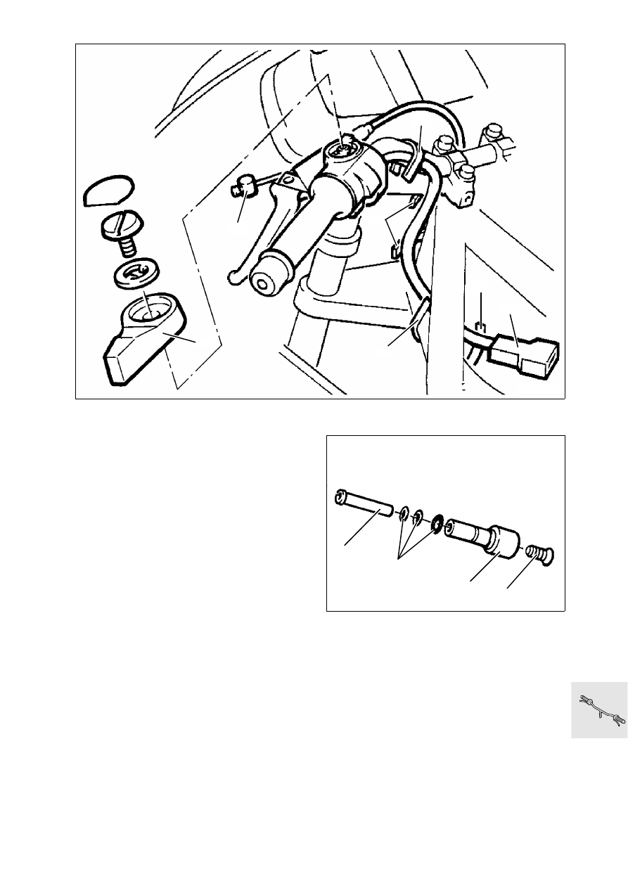
Removing and installing left handlebar 
fitting

Remove fuel tank.

[LT] 

Cut through cable clip (1)

Disconnect plug connection for clutch switch (2).

Detach cold start operating cable at lever (3).

Detach clutch cable (4) at clutch release lever, 
then at handlebar lever.

Removing and installing handlebar weight 

Release countersunk screw (1)

Pull out handlebar weight (2).

Pull out threaded sleeve (3) with screw.

Note O-ring (4).

LT320010

3

4

2

1

1

1

1

LT320020

1

2

3

4

32.6

Cut open rubber grip (1) and remove.

Release multifunction switch (2).

Loosen clamping screw (3) of handlebar fitting.

Remove fitting from handlebar.

Install in the reverse order of removal.

L

 Note:

Bond rubber grip with Loctite 454 on handlebar.

Tightening torque:

Clamping screw, handlebar fitting

.................. 5 Nm

Settings:

Clutch play at handlebar lever

...............4 ± 0.5 mm

............................................. (0.15748 ± 0.0197 in)

Cable length at clutch release lever

.......75 ± 1 mm 

............................................. (2.95275 ± 0.0394 in)

LT320030

1

3

2

32.7

Removing and installing right handle-
bar fitting

Remove fuel tank.

[LT] Cut through cable clip (1).

Disconnect plug connection (2) for brake light 
switch.

Release brake line (3) and close off.

Release multifunction switch (4).

Loosen cover (5) for accelerator cable.

Detach accelerator cable (6).

Remove handlebar weight (7).

Loosen clamping screw (8) from fitting housing.

Remove fitting.

Cut through rubber grip and remove.

Install in the reverse order of removal.

e

 Caution:

Top up brake fluid, vent system!

L

 Note:

Turn connection piece (3) of the brake line such that 
the brake line does not chafe at any point when the 
handlebar is turned.

Tightening torques:

Brake line ........................................................7 Nm
Bleed screw.....................................................7 Nm
Clamping screw...............................................5 Nm

Setting:

Accelerator cable play

............. 0.75 mm (0.0295 in)

LT320040

3

1

1

4

4

2

1

LT320050

8

7

6

5

32.8

Removing and installing handlebar

Remove fuel tank.

Remove handlebar cover (1).

Disconnect plug connections for switches.

Remove left and right handlebar fittings.

Release top sections of clamping block (2).

Install in the reverse order of removal.

Tightening torque:

Clamping screws

.......................................... 22 Nm

LT320060

1

2

32.9

Removing and installing handlebar 
clamping blocks

Remove stop plate (3).

Remove clamping blocks (4).

Drive out handlebar mounting with drift.

Install in the reverse order of removal.

Tightening torque:

Clamping block

............................................ 16 Nm

LT320070

4

3

32.10

Removing and installing accelera-
tor cable

Remove fuel tank.

Remove cable cover (1) on handlebar fitting.

Detach cable.

Turn in cam disc on throttle stub pipe (2) and de-
tach cable.

Install in the reverse order of removal.

L

 Note:

When installing, first attach cable at cam disc. Fit ca-
ble without kinks.

Adjust cable play at adjusting screw (3).

Accelerator cable play:

Desired value

.......................... 0.75 mm (0.0295 in)

LT320080

1

3

2

32.11

Removing and installing clutch 
cable

Remove fuel tank.

Detach clutch cable (1) at clutch release lever.

Pull clutch hand lever and press out nipple (2).

Unscrew set screw (3) from fitting housing.

Cut through cable clip and pull out operating 
cable.

Install in the reverse order of removal.

L

 Note:

Ensure the operating cable is fitted correctly, with 
no kinks.

Adjust cable after fitting.

Settings:

Play at handlebar lever

.........................4 ± 0,5 mm

............................................. (0.15748 ± 0.0197 in)

Cable length at clutch release lever

.......75 ± 1 mm

............................................. (2.95275 ± 0.0394 in)

Adjusting instructions:
See Group 00, “Checking clutch operating clear-
ance, adjusting if necessary”.

LT320090

1

2

3

32.12

Removing and installing operating 
cable for increasing starting speed

Remove fuel tank.

Remove operating lever (1).

Detach cable (2).

On throttle rail, release locknut (3) from adjusting 
screw (4) and unscrew adjusting screw.

Detach nipple (5).

Remove cable by pulling from below.

Install in the reverse order of removal.

L

 Note:

Fit cable without kinks. Check setting of start speed 
increase.

Adjusting instructions:
See Group 00, “Checking clutch operating clear-
ance, adjusting if necessary”.

LT320100

4

2

3

5

1


Content   ..  26  27  28  29   ..