BMW AG Motorcycle (K1100LT, K1100RS). Manual - part 17
 

  Index      Manuals     BMW AG Motorcycle (K1100LT, K1100RS). Repair Manual


Search            


Content   ..  15  16  17  18   ..


BMW AG Motorcycle (K1100LT, K1100RS). Manual - part 17


16.7

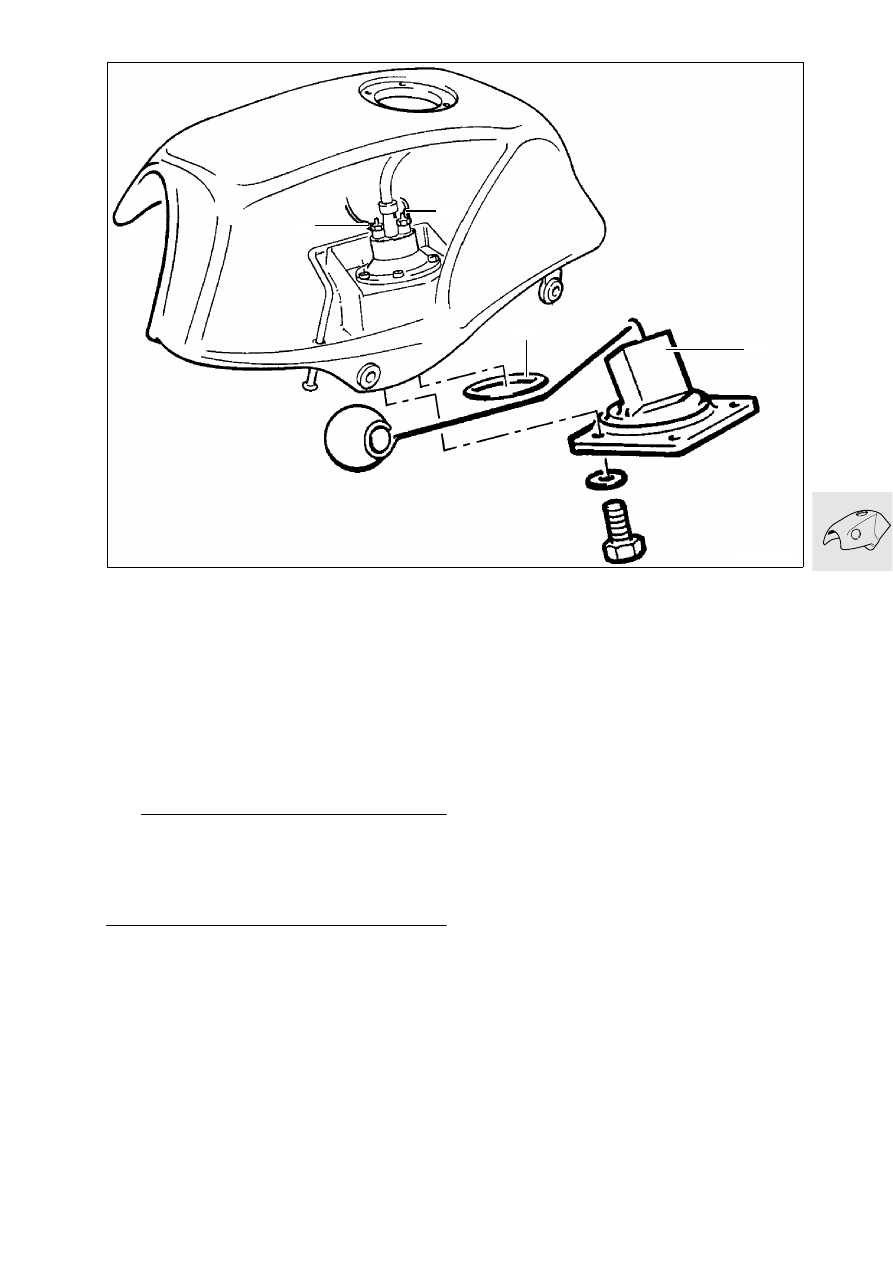
Removing and installing fuel level 
sensor

Removing and installing fuel level 
sensor

Remove and empty fuel tank.

Remove filler neck.

Release electrical connections (1/2) at the fuel 
pump.

Pull back insulation a little and remove fuel level 
pickup (3) from the outside.

Install in the reverse order of removal.

L

 Note:

Note installation location of gasket (4). Check that 
the lever moves smoothly.


Electrical connections:
Yellow

= +, 

M 4 connection thread

Black

= –,

M 5 connection thread

LT160030

2

3

4

1

16.8

Removing and installing fuel pump

Remove and empty fuel tank.

Remove filler neck.

Release electrical connections (1/2) at the fuel 
pump.

Release hose clips (3/4) and detach lines.

Compress clips (arrows) on retaining ring and 
pull out pump.

Pull filter (5) off pump.

Pull off rubber-metal connection (6) together with 
retaining ring.

Install in the reverse order of removal.

L

 Note:

The rubber-metal unit must be felt to engage on the 
fuel pump.
Note position of marking on rubber-metal unit and 
filter with respect to each other.
Electrical connections:
Yellow 

= +, 

M 4 connection thread

Black

= –, 

M 5 connection thread

The positive pole of the fuel pump must face oppo-
site the positive marking on the retaining ring.
Install pump such that both markings are located on 
the left-hand side of the motorcycle.

LT160040

2

6

1

4

3

5

16.9

Checking fuel pump pressure

Connect test pressure gauge, 
BMW No. 16 1 500, on the delivery side.

Run engine at idle speed.

Fuel pressure:

Nominal value

............................ 2.5 bar (36.26 psi)

If the fuel pressure is lower, check pump, fuel fil-
ter and line.

LT160050

16 1 500

16.10

17.1

Contents

Page

17

Technical data

................................................................................................................................ 3

Changing coolant 

.........................................................................................................................5

Draining coolant

 ...............................................................................................................................5

Filling with coolant

 ..........................................................................................................................5

Removing and installing thermostat 

..................................................................................6

Checking thermostat

 .....................................................................................................................6

Removing and installing radiator 

.........................................................................................7

Removing and installing fan 

...................................................................................................8

Removing and installing coolant hoses 

...........................................................................9

Checking cooling system 

.......................................................................................................10

Checking cap for filler neck

 ......................................................................................................10

Checking coolant system for leaks

 .......................................................................................10

Troubleshooting 

..........................................................................................................................11

17 Radiator

17.2

17.3

17

Technical data

K 1100 LT

K 1100 RS

Cooling system capacity

l(Imp.gal) 3.0 (0.66)

+ 0.4 (0.088) 

in expansion tank

Coolant

Antifreeze
Water

%
%

Concentration

 (

down to

 - 28 °C)

40
60

Only use nitride-free long-term frost and corro-
sion protection agents

Thermostat opens at

°C 85

Cut-in temperature for fan

°C 105

Cut-in temperature for coolant warning lamp

°C 115

Pressure relief valve in cap opens at

bar (psi) 1.0 = 120 °C (14.504 = 120 °C)

Vacuum valve in cap opens at

bar (pis) - 0.1 (-1.4504)

17.4


Content   ..  15  16  17  18   ..