BMW AG Motorcycle (K1100LT, K1100RS). Manual - part 15
 

  Index      Manuals     BMW AG Motorcycle (K1100LT, K1100RS). Repair Manual


Search            


Content   ..  13  14  15  16   ..


BMW AG Motorcycle (K1100LT, K1100RS). Manual - part 15


13.5

Adjusting idle speed

L

 Note:

The basic setting (ignition, valve clearance) must be 
correct.

Remove knee pad.

Remove left side fairing.

Remove protective caps (1) at the vacuum con-
nections.

Connect connection hoses of the Synchrotester, 
BMW No. 13 0 800, one after the other (note 
hose markings 1-4 on tester housing).

Connect tester to vehicle with the corresponding 
adapter lead.

Start engine and run at a standstill for app. 10 
minutes if not already warm.

e

 Caution:

Do not run for more than 20 minutes at a standstill.

Run the engine at idle speed.

Select “bar diagram” and maximum resolution.

L

 Note:

If the differences between the individual columns 
are too great (more than 2...5 mm 
(0.07874...0.19685 in)), switch over to curve display 
and compare the individual cylinders with each oth-
er; perform fault diagnosis procedure if necessary.

Repair any faults found.

e

 Caution:

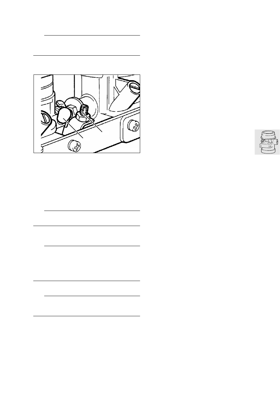
Throttle adjusting screw (2) is secured with lacquer 
and must not be turned.

Adjust synchronisation and idle speed by turning 
the air control screws until the bars/curves are at 
the same height; adjust engine idle speed.

Idle speed

......................................... 950 ± 50 rpm

LT000280

2

1

13.6

Checking start speed increase 
(choke), adjusting if necessary

Checking start speed increase

Remove left battery cover.

Set speed increase to limit stop (stage 2).

e

 Caution:

Screw (2) is sealed with lacquer and must not be 
turned.

L

 Note:

Stop face (1) must be in contact with screw (2) and 
the cable must have no play; if this is not the case, 
play at the cable must be adjusted.

Check stop face (1).

Adjusting start speed increase

Set speed increase to limit stop (stage 2).

Loosen locknut (3).

Press lever with stop face (1) against screw (2).

Turn adjusting screw (4) until there is no play at 
the cable.

Retighten locknut (3)

.

LT130030

4

1

3

2

13.7

Adjusting CO value

L

 Note:

Engine must be at operating temperature (85 °C).
Basic settings (ignition timing, valve clearances) 
must be correct.

Insert the measuring probe (arrow) app. 30 cm 
(12 in)
 into the silencer (muffler).

e

 Caution:

Do not perform this measuring work in an enclosed 
space: risk of asphyxiation.

L

 Note:

If the air extraction equipment is unsuitable, it may 
falsify the measurement.

Run the engine at idle speed.

e


Caution:

Adjusting screw (2) has no limit stop in both direc-
tions.

Turn adjusting screw (2) to obtain correct CO.

L

 Note:

Turn in direction (1) for a richer mixture; the CO value 
will rise to a maximum. Turning further in direction (1) 
has no effect on the CO value. 
Turn in direction (3) for a leaner mixture; the CO val-
ue will drop to a minimum. Turning further in direc-
tion (3) will cause the engine’s emergency-run 
programme to operate, but has no influence on the 
CO value.

e

 Caution:

If the engine’s emergency-run programme operates, 
fault 1111 will be memorised in the engine control 
unit.

If necessary, carry out fault diagnosis, rectify the 
fault and cancel the memory entry.

Using the BMW Synchrotester, adust idle speed 
at the recirculating-air screws.

CO value

................................... 1,5 ± 0,5 

% by vol.

Idle speed

..........................................950 ± 50 rpm

LT000290

LT000300

2

1

3

13.8

Removing/installing and checking/
adjusting throttle position sensor

Removing and installing throttle posi-
tion sensor

Unscrew the throttle position sensor and pull it 
off the throttle shaft.

Loosen wire keeper (1) and pull off multi-pin plug 
(2).

Install in the reverse order of work.

e

 Caution:

If the throttle position sensor has been removed, the 
basic settings must be checked and corrected if 
necessary after installing it again.

L

 Note:

See the booklet “BMW Diagnosis, Motronic MA 2.1 
with oxygen sensing” or “without oxygen sensing”, 
or the booklet “BMW Diagnosis MA 2.2”.

Checking trottle position sensor

Connect the diagnostic cable.

Press the left switch on the switch cabinet up to 
the detent position.

Switch on the ignition.

[MA 2.1]

 If the temperature warning light comes 

on, the throttle position sensor is correctly adjust-
ed.

[MA 2.1]

 If the temperature warning light does 

not come on, re-adjustment is needed.

[MA 2.2] 

If small zeroes are visible on the tester 

display, the throttle position sensor is correctly 
adjusted.

[MA 2.2

If no zeroes are visible, check the throt-

tle end stops and re-adjust.

Adjusting throttle position sensor

L

 Note:

Only adjust if the throttle position sensor was re-
moved or renewed.

Loosen the fastening for the sensor at the throttle 
rail.

Turn the sensor to the left or right until

 [MA 2.1] 

the temperature warning light comes on or 

[MA 2.2]

 small zeroes appear on the display.

Tighten the sensor in this position.

Pull off the diagnostic cable.

LT130060

2

1

13.9

Removing and installing air cleaner 
insert

Remove both knee pads.

Remove fuel tank.

Remove left and right heat-insulating bulkhead.

Release front clip (1) and both rear clips (2).

Slightly raise top section of air cleaner housing 
and remove air cleaner element.

L

 Note:

Note installed position of air cleaner element: letter-
ing at rear, arrow marking “TOP/OBEN”.

LT130070

1

2

13.10

Removing and installing air cleaner 
housing

Remove both knee pads.

Remove fuel tank.

Remove left and right side fairings.

Remove intake air guide.

Remove fairing retaining bracket on right.

Remove air cleaner.

Loosen wire retainer (1), disconnect multiplug (2) 
at air temperature sensor.

Release hose clips (3) at the air intake lines.

Loosen hose clip (4), detach crankcase breather 
ventilation hose.

LT130080

2

1

3

4

3

13.11

Loosen and pull off oil return pipe (5).

Loosen and pull off air return pipe (6).

Pull top section of air cleaner housing (7) out to 
the right.

Remove bottom section of air cleaner housing.

Install in the reverse order of removal.

Tightening torques:

Bottom section of air cleaner housing

.......... 21 Nm

Intake air pipe

................................................ 9 Nm

LT130090

5

6

7

13.12

Removing and installing throttle rail

Remove fuel tank.

Remove left fairing side section.

Remove left-hand heat-insulating bulkhead.

Release fuel hose (1) at injection rail.

Release injection rail (2) at cylinder head and pull 
out together with injectors.

Disconnect multiplug at throttle sensor.

L

 Note:

Only remove throttle sensor if it is to be replaced 
(basic setting necessary).

Detach throttle cable (3).

Detach operating cable (4) for start speed in-
crease.

Release hose clips at the air intake lines, loosen 
at the throttle coupling.

Remove throttle rail from stub pipe.

Pull air return pipe (5) off throttle rail.

Disconnect indicator lamp plug connection for 
start speed increase.

Install in the reverse order of removal.

L

 Note:

Do not change the location of the hose clips on the 
throttle coupling unions.
Firmly tighten hose clips at the air intake lines with 
special tool, BMW No. 31 1 500.

LT130100

1

3

4

2

LT130110

5


Content   ..  13  14  15  16   ..