BMW AG Motorcycle (F 650 GS). Manual - part 37
 

  Index      Manuals     BMW AG Motorcycle (F 650 GS). Repair Manual


Search            


Content   ..  35  36  37  38   ..


BMW AG Motorcycle (F 650 GS). Manual - part 37


61.10

Tightening torques:

Intake air silencer to retainer .......................... 9 Nm
Intake air silencer to oil tank ........................... 9 Nm
Connecting flange .......................................... 5 Nm
Fasteners, cover/
trim panel for turn indicator ............................ 3 Nm
Lid of electronic equipment box ..................... 4 Nm
Electronic equipment box to frame................. 5 Nm
Expansion tank to radiator.............................. 9 Nm
Ignition coil to cylinder head........................... 9 Nm

61 31 906 

Removing and installing 

coolant-temperature sensor

See Group 17

61 31 302 

Removing and installing side 

stand switch

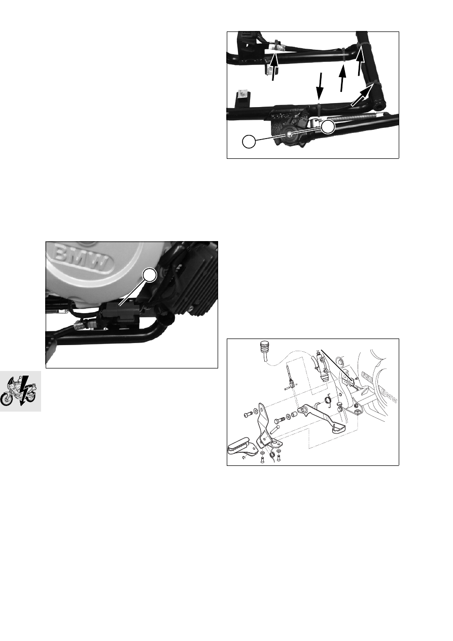
Place motorcycle on its centre stand.

Remove the engine guard.

Disconnect side-stand switch plug (1) and unclip 
the plug.

Disconnect plug of oxygen sensor.

Remove lower section.

Cut the cable ties at the lower section (arrows).

Remove retaining ring (2).

Lift switch (3).

Disconnect plug of switch (3).

Installation is the reverse of the removal proce-
dure.

Tightening torques:

Lower section to engine shell....................... 21 Nm
Lower section to main frame ........................ 21 Nm
Engine guard to frame.................................... 9 Nm

61 31 310 

Removing and installing 

rear-brake switch for brake light

Remove seat.

Remove right cover.

Remove brake-light switch (4).

Cut through the cable tie at the frame.

Remove the fuse box.

E610050

1

E610040

3

2

E340040

4

61.11

Remove the fastener securing the plug of the 
brake-light switch (arrow) at the frame

Disconnect plug of brake light switch.

Installation is the reverse of the removal proce-
dure.

Tightening torques:

Brake light switch, footbrake, to frame ........... 5 Nm

61 31 300 

Removing and installing 

front-brake switch for brake light

Place motorcycle on its centre stand.

Remove seat.

Remove left, right and centre covers.

Remove brake-light switch (1).

Cut through cable clip.

Disconnect the expansion tank and pull it to one 
side.

Remove the fasteners securing the oil tank and 
allow the oil tank to dangle to one side on the 
hoses.

Remove the starter relay from the holder.

Remove the lid of the electronic equipment box.

Cut through the cable tie holding the wiring har-
ness at the electronic equipment box.

Disengage cover from the anchorage on main 
frame on left.

Disconnect plug of brake light switch (2).

Push the cover over the cylinder head slightly to 
one side and remove the connector.

Tightening torques:

Oil tank to intake air silencer .......................... 9 Nm
Lid of electronic equipment box ..................... 4 Nm
Expansion tank to radiator ............................. 9 Nm
Brake-light switch to handlebar fitting ............ 3 Nm

E610060

E610070

1

E610030

2

61.12

61 33 000 

Removing and installing 

horn

Remove front mudguard.

a

....................................................See Group 46

Disconnect plug for horn (2).

Remove fastener securing horn (1).

Installation is the reverse of the removal proce-
dure.

Tightening torques:

Horn to bottom fork bridge ........................... 18 Nm
Lid of electronic equipment box ..................... 4 Nm
Front mudguard to fork bridge........................ 3 Nm

61 31 227 

Removing and installing 

idle-indicator switch

Remove cover for chain drive sprocket.

Remove fastener securing cable to idle-indicator 
switch.

Remove idle switch (3).

Installation is the reverse of the removal proce-
dure: pay particular attention to the following.

Clean the threads of the idle-indicator switch and 
coat with Loctite 243.

Tightening torques:

Idle-indictor switch
(clean thread + Loctite 243)............................ 3 Nm

Removing and installing front and 
rear ABS sensors

See Group 34

E610080

2

1

E610090

3

62.1

Contents

Page

62

Technical Data

............................................................................................................................... 3

Telltale/warning lights 

...............................................................................................................5

Removing and installing instrument panel 

.....................................................................6

Replacing telltale/warning lights 

.........................................................................................6

Disassembling and assembling instrument cluster

 .........................................................6

Removing and installing wiring harness

 ................................................................................7

62 Instruments

62.2

62.3

62

Technical Data

F 650 GS

Instruments

Speedometer and revolution counter lighting

W5/1.2 - 12V 1.2W

Telltale and warning lights

Flashing turn indicator

Idle

Oil pressure

Water temperature

High (main) beam headlight

ABS

Fuel gauge

W5/1.2 - 12V 1.2W

W5/1.2 - 12V 1.2W

W5/1.2 - 12V 1.2W

W5/1.2 - 12V 1.2W

W5/1.2 - 12V 1.2W

W5/1.2 - 12V 1.2W

W5/1.2 - 12V 1.2W

62.4

62.5

Telltale/warning lights

1 Water temperature
2 Oil pressure
3 Idle
4 High (main) beam headlight
5 Fuel gauge
6 ABS
7 Flashing turn indicator
8 Speedometer lighting
9 Revolution counter lighting

E620050

1

2

4

6

7

3

5

9

8


Content   ..  35  36  37  38   ..