BMW AG Motorcycle (F 650 GS). Manual - part 14
 

  Index      Manuals     BMW AG Motorcycle (F 650 GS). Repair Manual


Search            


Content   ..  12  13  14  15   ..


BMW AG Motorcycle (F 650 GS). Manual - part 14


11.48

21 21 000 

Installing clutch

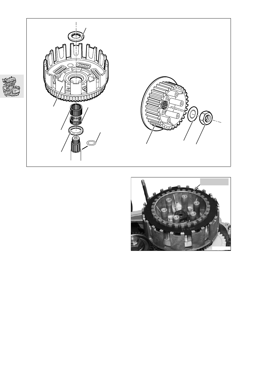
Installing clutch cage

Place thrust washer (1) on compensating shaft.

Coat needle sleeves (3, 5) with oil and install, 
with the small sleeve (5) down.

Insert O-ring (2) into groove under splines.

Install clutch cage (4); gears must all be in mesh.

Install thrust washer (6) and press it against the 
O-ring until it is firmly seated and does not spring 
back.

Installing driver

Insert driver (7) and coat internal splines with 
Optimoly MP 3.

Fit locking washer (8); it must engage securely.

Clean threads of compensating shaft and hexa-
gon nut (9), coat threads with Loctite 243 and in-
stall nut.

Insert locating ring, BMW No. 21 4 600.

Tighten hex nut and bend wings of locking 
washer (8).

Tightening torque:

Driver to compensating shaft
(clean thread + Loctite 243)........................ 140 Nm

E110430

9

8

7

4

6

2

1

3

5

E110260

21 4 600

11.49

Installing pressure plate

Insert the plates, starting with a steel plate. Insert 
steel and lined plates alternately.

L

 Note:

Insert the topmost plate (identified by a black spot) 
in the offset groove of the clutch cage.

Install pressure plate (2).

L

 Note:

All springs (3) must be renewed after each clutch re-
pair.

Install springs (3).

Uniformly tighten screws (4) with washers (5) in 
diagonally opposite sequence.

Fit gasket.

Position thrust head (1) correctly in relation to the 
releaser shaft and hold temporarily in position 
with grease.

Align splines on water pump driven gear with 
driving gear on balancing shaft.

Fit left engine cover and install securing screws.

L

 Note:

Always replace selector shaft seal in clutch cover.

Install selector shaft sealing ring in clutch cover 
with sliding sleeve, BMW No. 21 4 620, and drift, 
BMW No. 21 4 630.

Tightening torque:

Pressure plate to driver ................................ 10 Nm
Engine cover, left ......................................... 10 Nm

11 26 500 

Installing countershaft for 

starter motor

Turn engine in assembly fixture so that magnet 
side is uppermost.

L

 Note:

Oil the bearing bushing for freewheel gear (6) and 
the straight pins.

Slide freewheel gear (6) with the press-fit bearing 
bushing, onto the crankshaft.

Push intermediate starter gear (7) on to the 
straight pin.

Engage double gear wheel (9) on locating pin.

Install spacer sleeve (10) and thrust washer (8).

F110590

1

2

3

4

5

E110360

6

8

9

10

7

11.50

12 11 070 

Installing magnetic ignition 

trigger

e

 Caution:

Tapers on crankshaft and magnet hub and hex nut 
must be clean and free of grease.

Apply a thin coat of Loctite 648 to the magnet 
hub taper.

Oil freewheel in freewheel housing.

Slide magnet wheel (1) onto crankshaft: woodruff 
key and keyway must be aligned.

Rotate starter double gear (2) counter-clockwise 
to enable the freewheel to slide on to the collar of 
the freewheel gear.

Clean the threads on the crankshaft and the 
threads of the nut.

Install snap ring and coat threads of hex nut with 
Loctite 243 and tighten.

Coat the rubber grommet (3) of the transmitter 
and the rubber grommet of the stator cable with  
3 Bond 1209
 and install in cover of engine block.

Fit gasket.

Screw assembly handle, BMW No. 12 5 500
into the central hole in the right engine cover.

Fit right engine housing cover and bolt together.

Remove assembly handle and screw in cover.

Tightening torque:

Magnetic hub
(clean thread + Loctite 243)........................ 180 Nm
Engine cover, right ....................................... 10 Nm

E110370

2

1

E110380

3

11.51

11 25 050 

Installing piston

Coat the small end bore and the piston pin bore 
in the piston with Optimoly MP 3.

e

 Caution:

Note the mark on the exhaust side of the crown ap-
plied on disassembly.

Install the piston.

Press the piston pin in with drift, 
BMW No. 11 6 581
.

Install piston pin circlip with mandrel, 
BMW No. 11 6 581, and adapter, 
BMW No. 11 6 583.

Assembly sequence:

Place piston pin circlip (2) flat on bench.

Place sleeve (1) over the single-hook circlip (2) 
so that the ring gap is opposite the flat on the 
sleeve and the hook is in the groove.

Press the circlip into the sleeve.

Using the domed side of assembly drift (3), push 
the circlip in as far as possible.

Turn the assembly drift round and push in the cir-
clip until seated in the groove.

Position sleeve, BMW No. 11 6 583, with instal-
lation arbor, BMW No. 11 6 581, against piston.

e

 Caution:

Support side of piston.

Press piston pin circlip into piston with firm pres-
sure.

F110740

1

2

3

E110390

11 6 583

11 6 581

11.52

11 11 150 

Installing cylinder

Fit cylinder base gasket on engine housing: oil 
bore must be clear.

Oil the piston rings and press the sliding piston 
ring sleeve, BMW No. 11 6 510, over the piston 
rings from above so that the piston projects from 
the sliding sleeve by about 2 mm (0.08 in).

Slide timing chain and wire through chain aper-
ture of cylinder, then slide cylinder over piston.

Remove sliding sleeve.

Secure cylinder to engine housing hand-tight.

11 12 516 

Installing cylinder head

L

 Note:

Install a new cylinder head gasket.

Install the cylinder head gasket.

Use a wire hook to pull the timing chain through 
the cavity in the cylinder head.

Fit cylinder head with valves installed to cylinder.

Secure the cylinder head and cylinder loosely to-
gether with the collar screws and nuts.

E110400

11.53

Initially tighten the collar nuts of the cylinder head 
to 20 Nm (1-4) and then tighten to 60 Nm (5-8).

Tighten the fasteners of the cylinder head to cyl-
inder in the sequence as shown (9-14) to speci-
fied torque.

Tighten machine screws at base of cylinder.

Tightening torques:

Machine screws (chaincase) ........................ 10 Nm
Collar screws for cylinder head .................... 33 Nm
Collar nuts to cylinder head.............stage 1: 20 Nm

.......................................................stage 2: 60 Nm

E110151

7

8

3

2

1

13

14

12

10

5

4

11

14

14

6

9

11.54

11 31 529 

Installing camshaft and adjust-

ing valves

Oil outside of bucket tappets and reinstall on 
original valves.

Measure thickness of shims with micrometer and 
note down dimension.

Place lower part of camshaft carrier (1) on cylin-
der head.

Fit camshafts with cam lobes facing upwards, 
press down by hand and measure valve clear-
ance with feeler gauge.

L

 Note:

The decompressor in the exhaust camshaft must 
not press against the bucket tappet, or else the 
valve clearance will be incorrect.

Note down dimensions.

Determine the difference between the nominal 
and actual values.

Check thickness of shims with micrometer and 
replace as appropriate.

Valve clearances:
Inlet valve ............ 0.05...0.10 mm (0.002...0.004 in)
Exhaust valve ...... 0.25...0.30 mm (0.010...0.012 in)

Insert chain guide rail (3) in chain cavity.

e

 Caution:

Marks on the timing-chain sprockets (arrow) must 
be parallel with the cylinder head, the bores in the 
timing-chain sprockets must be at the top (TDC po-
sition).

Oil the camshaft journals.

Install the exhaust camshaft first, then the inlet 
camshaft.

Install the upper part of the camshaft carrier (2) 
and tighten.

Clean the threads of the chain guide 
fasteners (4), coat with Loctite 243 and install 
the fasteners.

E110420

1

2

4

3

E110410

11.55

Check valve clearances.

Install chain tensioner and tighten threaded fas-
tener with sealing ring.

Remove all traces of the cylinder head cover 
gasket and clean the sealing face with degreas-
ing agent. Also clean the groove and the seating 
faces for the gasket.

Install valve cover with gasket.

Connect the oil lines to the engine block.

L

 Note:

Install the oil return line with the tab at the bottom 
and the oil feed line with the tab at the top.

Connect the oil lines to the cylinder head.

Take out locating pin, BMW No. 11 6 570, and 
insert screw plug with sealing ring.

Install the spark plug.

Fit the filter element onto the oil-filter cover.

Coat the O-ring of the filter element lightly with 
oil.

Check the O-ring of the oil-filter cover for dam-
age and replace if necessary.

Install the oil-filter cover complete with filter ele-
ment.

Install starter motor.

Tightening torque:

Camshaft bearing cap .................................. 10 Nm
Chain guide to bearing cap
(clean threads + Loctite 243) ........................ 10 Nm
Timing-chain tensioner to cylinder head ....... 40 Nm
Cylinder head cover to cylinder head ........... 10 Nm
Threaded plug in left side of engine block .... 25 Nm
Oil line to engine block ................................. 35 Nm
Oil line to cylinder head .................................. 8 Nm
Spark plug in cylinder head .......................... 20 Nm
Starter motor to clutch housing cover .......... 10 Nm
Oil filter cover ............................................... 10 Nm


Content   ..  12  13  14  15   ..