BMW AG Motorcycle (F 650 GS). Manual - part 12
 

  Index      Manuals     BMW AG Motorcycle (F 650 GS). Repair Manual


Search            


Content   ..  10  11  12  13   ..


BMW AG Motorcycle (F 650 GS). Manual - part 12


11.32

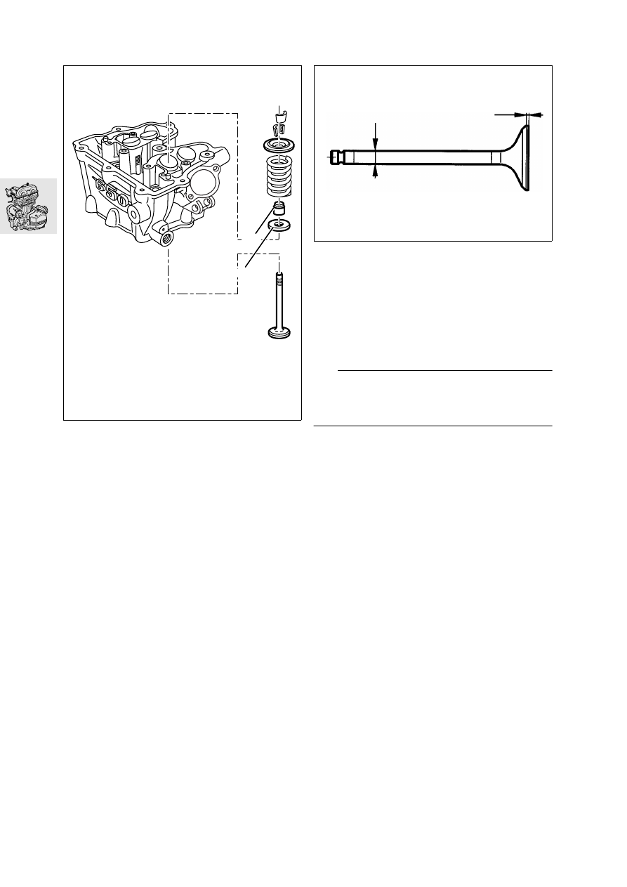
11 34 800 Installing valve stem seal

Install bottom valve spring retainer (1).

Use a drift, BMW No. 11 6 650, to insert valve 
stem seal (2).

Checking valve for wear

Check valve stem diameter and valve head seat 
width.

Wear dimensions for valve:
Stem diameter
Inlet valve ........................... min. 4.89 mm (0.177 in)
Exhaust valve ..................... min. 4.89 mm (0.177 in)

Check valve for runout.

L

 Note:

Remove oil carbon from valve and deburr grooves 
for valve collets with an oilstone.
For wear limits, see Technical Data.

Check grooves for valve collets.

E110120

1

2

F110190

11.33

11 34 020 Installing valves

Install valve with shrink-fit tube.

L

 Note:

Remove the shrink-fit tube.

Install valve spring and valve spring retainer.

Secure the cylinder head to support plate, 
BMW No. 11 0 523.

Secure adapter plate, BMW No. 11 0 521, sup-
port, BMW No. 11 5 691, spindle, 
BMW No. 11 5 692, nut, BMW No. 11 5 693
and thrust plate, BMW No. 11 0 522.

Press down the valves with the thrust plate.

L

 Note:

Install valve collets with a small amount of grease to 
facilitate assembly.

Insert the valve collets.

Check bucket tappets for damage and reinstall 
on original valves.

11 11 150 

Removing cylinder

Separate the cylinder base from the engine 
block.

e

 Caution:

When removing cylinder, make sure that the piston 
does not strike the engine block.

Remove cylinder.

Checking cylinder

Check cylinder face and sealing faces for dam-
age and blow out oil ducts for chain tensioner.

Measure cylinder bore at 55...65 mm 
(2.17...2.56 in) from the upper edge with an inter-
nal micrometer at three points (1, 2, 3).

Wear limits for cylinder bore:
Cylinder A ................... max. 100.03 mm (3.9382 in)
Cylinder B ................... max. 100.04 mm (3.9387 in)

E110130

11 0 523

11 0 521

11 5 692

11 0 522

11 5 691

E110140

E110150

2

1

3

11.34

11 25 050 

Removing piston

Remove piston pin circlips.

Press out piston pin with drift, 
BMW No. 11 6 581
.

L

 Note:

Mark exhaust-valve side on piston crown.

11 25 671 

Disassembling piston

Remove piston rings with piston ring pliers.

Carefully clean piston.

Check piston for signs of damage.

Determining clearance of piston in 
cylinder

Measure cylinder bore at 55...65 mm 
(2.17...2.56 in) from the upper edge with an inter-
nal micrometer at three points (1, 2, 3).

Make a note of the largest value as 
dimension “A”.

Measure piston diameter “B” at distance 
H=16 mm (0.63 in) from the lower edge at a right 
angle to the piston pin axis.

L

 Note:

Determine piston clearance:
Dimension “A” minus dimension “B” = piston clear-
ance

Piston clearance:
When new ... 0.024...0.040 mm (0.0009...0.0016 in)
Wear limit ...................... max. 0.100 mm (0.0039 in)

E110150

2

1

3

E110160

B

H

11.35

Determining piston ring gaps

Slip piston ring 60 mm (2.36 in) into cylinder from 
top and use a feeler gauge to measure ring gap.

Wear dimension:
Ring gap (all piston rings) .............. 1.0 mm (0.04 in)

Determining piston pin clearance

Measure diameter of piston pin bores in piston 
stroke direction using an internal micrometer.

Measure both ends of piston pin with microme-
ter.

Wear limits:
Bore dia. in piston, 
vertical ........................max. 22.030 mm (0.8673 in)
Piston pin dia. ..............min. 21.980 mm (0.8654 in)
Radial clearance in 
piston ............................max. 0.050 mm (0.0019 in)

11 25 671 

Assembling pistons

L

 Note:

The “Top” must face towards the piston crown.
Install the piston rings with their gaps offset 
by 120 °.

1 Groove for rectangular-section ring
2 Stepped micro-taper ring
3 Groove for spring-steel oil control ring

Use feeler gauge to measure float of piston rings 
in groove.

Wear limit, 
ring float in groove................... 0.150 mm (0.006 in)

12 11 070 

Removing ignition magnet

Remove retainer on right engine housing cover.

Remove the central plug and install handle, 
BMW No. 12 5 500.

Remove the cover, noting the thrust 
washer (arrow).

If necessary, remove ignition trigger (4).

E110170

1

2

3

E110180

12 5 500

E110190

E110200

4

11.36

Unscrew hex nut.

Heat hub to 80 °C (176 °F).

L

 Note:

Use temperature measuring device, 
BMW No. 00 1 900, to check the temperature.

Using puller, BMW No. 12 5 510, pull off magnet 
rotor.

11 26 500 

Removing countershaft for 

starter

Remove thrust washer (1) and spacer sleeve (2).

Remove double gear (4).

Pull off idler gear (3).

Remove freewheel gear (5).

E110210

12 5 510

E110220

1

2

3

4

E110230

5

11.37

12 11 077 

Disassembling and 

assembling freewheel

Disassembling freewheel

1 Machine screw
2 Magnet rotor
3 Freewheel
4 Lock ring
5 Freewheel housing
6 Freewheel gear

d

 Warning:

Securing screws (1) are secured with Loctite 648 
and considerable torque is required to release them.

Release retaining screws (1).

Lift off freewheel housing (5).

Remove circlip (4).

Remove freewheel gear (3).

Check freewheel housing and freewheel for 
wear, isolated chatter marks are permissible.

Assembling freewheel

Installation is the reverse of the removal proce-
dure: pay particular attention to the following.

Install freewheel with arrow mark (arrow) down.

E110240

5

4

2

3

6

1

E110300

11.38

Engage the lugs on the circlip in the recesses in 
the freewheel gear.

Clean the threads of the securing screws and 
freewheel housing, coat threads with 
Loctite 648 and install the screws.

Check locking function and locking direction of 
freewheel.

Tightening torques:

Machine screw
(clean threads + Loctite 648) ........................ 35 Nm 

21 21 000 

Removing clutch

Turn engine round in assembly fixture.

Remove left retaining for engine housing cover 
and remove cover.

Removing pressure plate

Remove hex screws (2) in diagonally opposite 
sequence.

Lift off complete pressure plate (1).

Removing clutch plates

e

 Caution:

The topmost clutch plate is offset. Make sure this 
plate is installed in the correct position.

Take plate cluster out of clutch cage. 

Using locating ring, BMW No. 21 4 600, prevent 
clutch cage (4) and driver (3) from moving and 
unscrew hex nut.

Pull off driver.

Pull off clutch cage and ring gear.

e

 Caution:

Note the backup washer at the bottom.

Pull off needle cages.

Remove the backup washer.

E110250

2

1

E110260

21 4 600

4

3

11.39

11 41 000 

Removing and installing oil 

pump

Removing oil pump

Remove circlip (1) from idler gear.

Remove the retaining rings of the oil-pump 
gears (2) and disengage the oil-pump gears.

Remove idler gear (3).

Remove needle rollers (4).

Remove thrust washers (5).

Remove countersunk screws from cover and lift 
off cover (6).

Inspecting oil pump

Using feeler gauges, measure the clearance be-
tween the inner and outer rotors and between 
the outer rotor and the housing.

Permissible face runouts between:
Inner and outer rotor ......... max. 0.25 mm (0.010 in)
Radial clearance................ max. 0.25 mm (0.010 in)
Axial clearance between
rotors and cover ................ max. 0.25 mm (0.010 in)

Installing oil pump

7 Inner rotor
8 Outer rotor
9 Cover
10 Markings
11 Needle roller

Installation is the reverse of the removal proce-
dure: pay particular attention to the following.

L

 Note:

Markings (5) must be visible.

Oil the inner and outer rotors.

Clean the threads of the countersunk screws 
and coat with Loctite 243.

Tightening torque:

Countersunk screws in oil-pump cover
(clean threads + Loctite 243) .......................... 6 Nm

E110270

1

2

E110280

3

4

5

6

F110370

8

7

11

9

10


Content   ..  10  11  12  13   ..