Motorcycle BMW R1150RT. Manual - part 63
 

  Index      motorcycles     Motorcycle BMW R1150RT - service repair manual 2001 year


Search            


Content   ..  61  62  63  64   ..


Motorcycle BMW R1150RT. Manual - part 63


33.19

d


Warning:

Integral ABS When removing and installing the 
brake caliper, force back the pistons carefully to en-
sure that the wheel-circuit reservoir does not over-
flow.
If fluid escapes, proceed in accordance with “In-
structions for filling reservoir” (

a

00.48).

Install brake caliper.

e

 Attention:

Do not damage brake pads; keep the brake caliper 
parallel to the brake disc when installing.

Integral ABS Install sensor (6).

Load approx. 85 kg (187 lbs) onto motorcycle 
and tighten loose reaction link (5).

Tightening torque:

Fixed bearing stud bolt
(threads cleaned + Loctite 2701) ................ 160 Nm
Floating bearing stud bolt 
(threads cleaned + Loctite 2701) .................... 7 Nm
Locknut ...................................................... 160 Nm
Reaction link to rear-wheel drive unit............ 43 Nm
Wheel studs  .............................................. 105 Nm
Brake caliper to rear-wheel drive unit ........... 40 Nm

Capacity:
Initial  fill/oil  change .................. approximately 0.25 l 

................................ (0.44 Imp. pint/0.27 US quart)

Oil grade:
Brand-name SAE 90 hypoid gear oil, API GL 5

33 53 

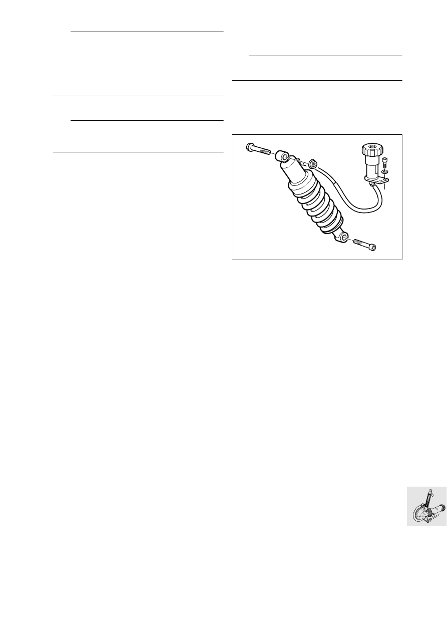
Removing and installing spring 

strut

L

 Note:

To remove the spring strut, support the rear axle.

Remove the seat.

Slacken the fasteners of the silencer, if neces-
sary.

Remove rear brake caliper.

Remove rear wheel.

Remove the seat adjuster.

Remove hydraulic spring adjuster.

Remove spring strut.

Installation is the reverse of the removal proce-
dure.

Tightening torque:

Spring strut to rear frame ............................. 50 Nm
Spring strut to swinging arm
(clean thread + Loctite 243).......................... 58 Nm
Hydraulic spring preload adjuster
to rear frame section .................................... 22 Nm

R22330020

33.20

33 17 350 

Removing and installing rear 

swinging arm

33 17 

Removing rear swinging arm.

Remove side panels (

a

46.8).

Remove final-drive unit.

Remove rear spring strut.

Remove the footrest plates.

Remove holder for brake hose on the swinging 
arm.

Swinging-arm bearing studs are secured with 
Loctite: heat to max. 120 °C (248 °F) to release.

Loosen floating bearing stud bolt (1).

Loosen fixed bearing stud bolt (2).

Remove floating bearing/fixed bearing stud 
bolts.

Remove swinging arm with gaiter.

A

A

R22330030

2

1

33.21

33 17 381 

Removing and installing taper 

roller bearing

Remove taper roller bearing with counter-sup-
port, BMW No. 00 8 572, and internal 
puller 21/2, BMW No. 00 8 571, with support for 
ring.

Pull out outer race with internal puller 21/5, 
BMW No. 00 8 563.

To install the bearing, heat the swinging arm to 
80 °C (176 °F).

Drive in bearing with drift, BMW No. 33 5 700.

33 17 465 

Removing and installing fle-

xible gaiter 

Pull flexible gaiter with circlip out of swinging 
arm.

When installing, coat inner and outer sealing lips 
(arrows) with Staburags NBU 30 PTM.

e

 Attention:

Drive shaft clearance when suspension is com-
pressed: 
The gap in the circlip must be in the horizontal 
plane.

26 11 

Removing drive shaft

e

 Attention:

Avoid scratching painted parts; use an underlay if 
necessary.

Press off drive shaft.

Checking universal joint for wear

Determine axial and radial play.

26 11 

Installing drive shaft

Coat the splines on the output shaft with 
Staburags NBU 30 PTM.

Fit drive shaft to output shaft.

Engage the snap ring by tapping it gently (plastic 
hammer).

LT330370

00 8 563

00 8 571

00 8 572

KR330340

R21330050

KR330360

33.22

33 17 

Installing rear swinging arm

Slide swinging arm over drive shaft as far as pos-
sible until rubber gaiter connects on housing 
neck.

Install fixed-bearing stud bolt (2) with Loctite.

e

 Attention:

When tightening threaded fasteners coated with 
Loctite 2701, always apply final torque without de-
lay.
Allow at least 3 hours for the Loctite to cure.

Screw in floating bearing stud (1) with Loctite.

Tighten the fixed bearing stud (2).

Tighten floating bearing stud (1).

Tighten locknut (3).

Secure spring strut.

Secure holder for brake hose on the swinging 
arm.

Install footrest plates.

Install the rear wheel drive.

Install fairing side sections.

Tightening torque:

Fixed bearing stud bolt 
(clean thread + Loctite 2701)...................... 160 Nm
Floating bearing stud
(clean thread + Loctite 2701).......................... 7 Nm
Locknut...................................................... 160 Nm
Spring strut to swinging arm
(clean thread + Loctite 243).......................... 58 Nm
Spring strut to rear frame ............................. 50 Nm

R22330030

A

A

2

1

3


Content   ..  61  62  63  64   ..