Kawasaki Ninja ZX-12R Motorcycle. Service Manual (2002-2005 year) - page 17
 

  Index      Manuals     Kawasaki Ninja ZX-12R Motorcycle. Service Manual (2002-2005 year)


Search            copyright infringement  


Content      ..     15      16      17      18     ..


Kawasaki Ninja ZX-12R Motorcycle. Service Manual (2002-2005 year) - page 17


16-36 ELECTRICAL SYSTEM

Ignition System

Spark Plug Installation

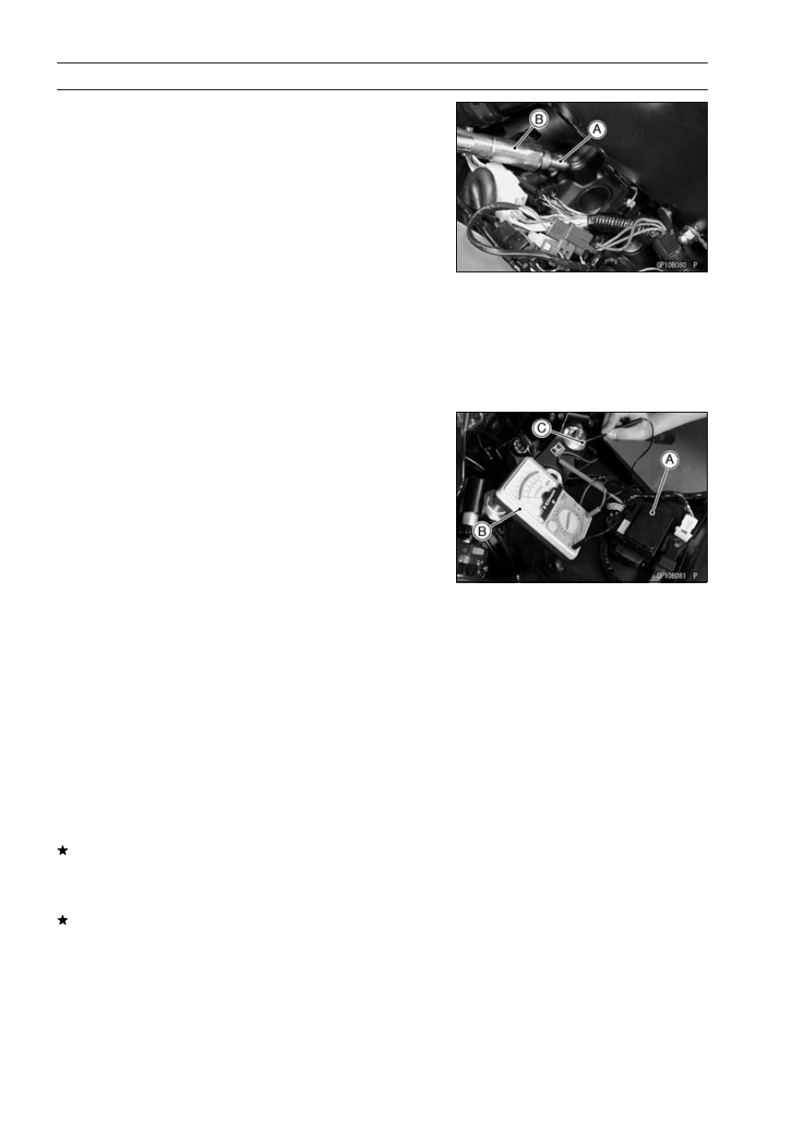
Insert the spark plug vertically into the plug hole with the
plug [A] installed in the plug wrench [B].

Owner’s Tool - Spark Plug Wrench, 16 mm: 92110-1132

Tighten the plugs.

Torque - Spark Plugs: 13 N·m (1.3 kgf·m, 115 in·lb)

Fit the stick coils securely.

Spark Plug Cleaning and Inspection

Refer to the Spark Plug Cleaning/Inspection in the Peri-
odic Maintenance chapter.

Spark Plug Gap Inspection

Refer to the Spark Plug Cleaning/Inspection in the Peri-
odic Maintenance chapter.

Interlock Operation Inspection

Remove:

Fuel Tank Cover (see Fuel System (DFI) chapter)

Do not disconnect the connectors.

1st Check

Measure the terminal voltage of the G/BK lead in the junc-
tion box connector [A] in accordance with the following
procedure.

Set the tester [B] to the 10 V DC range, connect it to the
G/BK lead and frame ground [C].

Connection

Tester (+) Terminal

G/BK Lead Terminal

Tester (–) Terminal

Frame Ground

Condition

Transmission Gear

1st Position

Clutch Lever

Release

Side Stand

Down

Turn the ignition switch on.

Read the voltage.

Interlock Operation Voltage

Standard:

4 V or more

If the voltage is lower than the standard, inspect the side
stand switch, starter lockout switch, gear position switch
and junction box. And their parts are normality, replace
the ECU.
If the voltage is standard, push the starter button to check
as follows.

If the starter motor does not turn, the ECU is good, and
check the starter system circuit.

If the starter motor turned, ECU is defective. Replace the
ECU.

ELECTRICAL SYSTEM 16-37

Ignition System

2nd Check

Raise the rear wheel off the ground with a stand.

Inspect the engine for its secure stop after the following
operations are completed.

Run the engine to the following conditions.

Condition

Transmission Gear

1st Position

Clutch Lever

Pull in

Side Stand

Up or Down

Gradually release the clutch lever, then the engine will
stop.

Run the engine to the following conditions.

Condition

Transmission Gear

1st Position

Clutch Lever

Release

Side Stand

Up

Set the side stand on the ground, then the engine will
stop.
If whichever may not be stopped, inspect the gear posi-
tion switch, starter lockout switch, side stand switch and
junction box.
If their parts are normality, replace the ECU.

IC Igniter Inspection

The IC igniter is built in the ECU [A].

Refer to the Interlock Operation Inspection, Ignition Sys-
tem Troubleshooting chart and Fuel System (DFI) chapter
for ECU Inspection.

Ignition System Inspection

16-38 ELECTRICAL SYSTEM

Ignition System

ELECTRICAL SYSTEM 16-39

Ignition System

Ignition System Circuit

ZX1200-B1/B2

1. Ignition Switch
2. Engine Stop Switch
3. Starter Button
4. Spark Plugs
5. Stick Coils
6. Side Stand Switch
7. Crankshaft Sensor
8. Camshaft Position Sensor
9. Throttle Sensor

10. Gear Position Switch

11. Junction Box

12. Ignition Fuse 10 A

13. Starter Lockout Switch
14. ECU Main Relay
15. ECU Fuse 15 A
16. Vehicle-down Sensor
17. Main Fuse 30 A
18. Battery
19. ECU (Electronic Control Unit)

*: U.S.A., Canadian, Australian

and Malaysian Models

**: Other than U.S.A., Canadian,

Australian and Malaysian Models

16-40 ELECTRICAL SYSTEM

Ignition System

ZX1200-B3

1. Ignition Switch
2. Immobilizer Antenna
3. Immobilizer Amplifier
4. Engine Stop Switch
5. Starter Button
6. Spark Plugs
7. Stick Coils
8. Side Stand Switch
9. Fuel Injector #1

10. Fuel Injector #2

11. Fuel Injector #3

12. Fuel Injector #4
13. Crankshaft Sensor
14. Camshaft Position Sensor
15. Gear Position Switch

16. ECU (Electric Control Unit)
17. Fuel Pump
18. Engine Ground
19. Battery
20. Main Fuse 30 A
21. Vehicle-down Sensor
22. ECU Fuse 15 A
23. Fuel Pump Relay
24. ECU Main Relay
25. Junction Box
26. Starter Relay
27. Ignition Fuse 10 A
28. Starter Lockout Switch
29. Meter Assembly

ELECTRICAL SYSTEM 16-41

Electric Starter System

Starter Motor Removal

Remove:

Battery Compartment Cover (see Battery Removal)
Terminal Nut [A]
Starter Motor Cable [B]

Remove:

Lower Fairing (see Frame chapter)
Coolant Reserve Tank
Starter Motor Mounting Bolts [A]

Pull out the starter motor [A].

Remove:

Terminal Nut [B]
Starter Motor Cable [C]

Starter Motor Installation

CAUTION

Do not tap the starter motor shaft or body. Tapping
the shaft or body could damage the motor.

When installing the starter motor, clean the starter mo-
tor legs [A] and crankcase [B] where the starter motor is
grounded.

Apply small amount of engine oil or grease to the O-ring
[A].

Install the starter motor and tighten the mounting bolts.

Torque - Starter Motor Mounting Bolts: 12 N·m (1.2 kgf·m,

106 in·lb)

16-42 ELECTRICAL SYSTEM

Electric Starter System

Starter Motor Disassembly

Take off the starter motor through bolts [A] and remove
both end covers [B] and pull the armature out of the yoke
[C].

The brush plate [A] and brushes come off with the left
-hand end cover [B].

Remove the terminal locknut [A] and terminal bolt [B], and
then remove the brush with the brush plate [C] from the
left-hand end cover.

Starter Motor Assembly

Install the brush plate and brushes [A], and then put the
armature [B] among the brushes.

Install the O-rings [A] as shown.

ELECTRICAL SYSTEM 16-43

Electric Starter System

Align the notch [A] in the brush plate with the end cover
notch [B] and the mark [C] on the yoke.

Align the line [A] marked on the yoke with the through bolt
hole [B].

Brush Inspection

Measure the length [A] of each brush [B].
If any is worn down to the service limit, replace the carbon
brush holder assembly [C] and the terminal bolt assembly
[D].

Starter Motor Brush Length

Standard:

12 mm (0.47 in.)

Service Limit:

8.5 mm (0.33 in.)

Commutator Cleaning and Inspection

Smooth the commutator surface [A] if necessary with fine
emery cloth [B], and clean out the grooves.

Measure the diameter [A] of the commutator [B].
If the commutator diameter is less than the service limit,
replace the starter motor with a new one.

Commutator Diameter

Standard:

28 mm (1.10 in.)

Service Limit:

27 mm (1.06 in.)

16-44 ELECTRICAL SYSTEM

Electric Starter System

Armature Inspection

Using the × 1

hand tester range, measure the resis-

tance between any two commutator segments [A].
If there is a high resistance or no reading (

) between any

two segments, a winding is open and the starter motor
must be replaced.

Using the highest hand tester range, measure the resis-
tance between the segments and the shaft [B].
If there is any reading at all, the armature has a short and
the starter motor must be replaced.

NOTE

Even if the foregoing checks show the armature to be
good, it may be defective in some manner not readily
detectable with the hand tester. If all other starter motor
and starter motor circuit components check good, but
the starter motor still does not turn over or only turns
over weakly, replace the starter motor with a new one.

Brush Lead Inspection

Using the × 1

hand tester range, measure the resis-

tance as shown.

Terminal Bolt and Positive Brush [A]
Brush Plate and Negative Brush [B]

If there is not close to zero ohms, the brush lead has
an open. Replace the terminal bolt assembly and/or the
brush holder assembly.

Brush Plate and Terminal Bolt Inspection

Using the highest hand tester range, measure the resis-
tance as shown.

Terminal Bolt and Brush Plate [A]
Terminal Bolt and Left-hand End Cover [B]

If there is any reading, the brush holder assembly and/or
terminal bolt assembly have a short. Replace the brush
holder assembly and the terminal bolt assembly.

Starter Relay Inspection

Remove:

Battery Tray (see Battery Removal)
Screw [A]
Cover [B]

ELECTRICAL SYSTEM 16-45

Electric Starter System

Remove:

Starter Cable [A]
Battery Cable [B] (disconnect)
Connector [C]
Starter Relay [D]

Connect the hand tester [A] and 12 V battery [B] to the
starter relay [C] as shown.
If the relay does not work as specified, the relay is defec-
tive. Replace the relay.

Testing Relay

Tester Range:

× 1

range

Criteria:

When battery is connected

0

When battery is disconnected

→ ∞ Ω

16-46 ELECTRICAL SYSTEM

Electric Starter System

Electric Starter Circuit

ZX1200-B1/B2

1. Ignition Switch
2. Engine Stop Switch
3. Starter Button
4. Junction Box
5. Starter Circuit Relay

6. Ignition Fuse 10 A
7. Starter Lockout Switch
8. Neutral Switch (in Gear

Position Switch)

9. Starter Motor

10. Starter Relay

11. Main Fuse 30 A

12. Battery

*: U.S.A., Canadian, Australian and Malaysian Models

**: Other than U.S.A., Canadian, Australian and Malaysian Models

ELECTRICAL SYSTEM 16-47

Electric Starter System

ZX1200-B3

1. Ignition Switch
2. Engine Stop Switch
3. Starter Button
4. Junction Box
5. Starter Circuit Relay
6. Ignition Fuse 10 A
7. Starter Lockout Switch
8. Side Stand Switch
9. Starter Motor

10. Starter Relay

11. Main Fuse 30 A

12. Battery

16-48 ELECTRICAL SYSTEM

Lighting System

The U.S.A., Canadian, Australian, and Malaysian models

adopt the daylight system and have a headlight relay in the
junction box. In these models, the headlight does not go
on when the ignition switch and the engine stop switch are
first turned on. The headlight comes on after the starter
button is released and stays on until the ignition switch is
turned off. The headlight will go out momentarily whenever
the starter button is pressed and come back on when the
button is released.

Headlight Beam Horizontal/Vertical Adjustment

Remove the left and right lower inner covers [A] (see
Frame chapter).

Turn the left and right horizontal adjusters [A] on the head-
light in or out until the beam points straight ahead.

Turn the left and right vertical adjusters [B] on the head-
light in or out to adjust the headlight vertically.

NOTE

On high beam, the brightest points should be slightly
below horizontal with the motorcycle on its wheels and
the rider seated. Adjust the headlight(s) to the proper
angle according to local regulations.

For US model, the proper angle is 0.4 degrees below
horizontal. This is 50 mm (2 in.) drop at 7.6 m (25
ft) measured from the center of the headlights with the
motorcycle on its wheels and the rider seated.

50 mm (2 in.) [A]
Center of Brightest Spot [B]
7.6 m (25 ft) [C]
Height of Headlight Center [D]

ELECTRICAL SYSTEM 16-49

Lighting System

Headlight Bulbs (Left and Right) Replacement

Remove:

Left and Right Lower Inner Covers
Headlight Connectors
Headlight Bulb Dust Covers
Hooks [A]
Headlight Bulbs [B]

CAUTION

When handling the quartz-halogen bulb, never
touch the glass portion with bare hands. Always
use a clean cloth. Oil contamination from hands or
dirty rags can reduce bulb life or cause the bulb to
explode.

Replace the headlight bulbs.

Fit the dust cover [A] with the Top mark [B] upward onto
the bulb [C] firmly as shown.

After installation, adjust the headlight aim (see Headlight
Beam Adjustment).

City Light Bulb Replacement

Remove:

Wind Shield (see Frame chapter)

Turn the socket [A] counterclockwise, and remove the
socket and bulb.

Pull the bulb [A] out of the socket.

CAUTION

Do not turn the bulb. Pull the bulb out to prevent
damage to the bulb. Do not use bulb rated for
greater wattage than the specified value.

16-50 ELECTRICAL SYSTEM

Lighting System

Tail/Brake Light Bulbs Replacement

Remove:

Rear Seat (see Frame chapter)
Seat Cover (see Frame chapter)

Turn the left and right sockets [A] counterclockwise, and
remove the sockets and bulbs.

Push and turn the bulb [A] counterclockwise and remove
it.

Insert a new bulb [A] by aligning its upper pin [B] with the
upper groove [C] in the socket, and turn the bulb clock-
wise.

Insert the socket by aligning its projection [A] with the up-
per groove [B], and turn it clockwise.

Tail/Brake Light Lens Assembly Replacement

Remove:

Seat Cover (see Frame chapter)
Left and Right Socket [C]
Mounting Bolts [B]
Lens Assembly [A]

Install:

Tighten the mounting bolts.

Torque - Tail/Brake Light Lens Bolts: 6.0 N·m (0.60 kgf·m,

53 in·lb)

Removed Parts

ELECTRICAL SYSTEM 16-51

Lighting System

Headlight Relays (High/Low) Inspection

Remove:

Wind Shield (see Frame chapter)
Headlight Relay (High Beam) [A]

Remove:

Headlight Relay (Low Beam) [A]
Right Upper and Lower Inner Covers (see Frame chap-
ter)

Connect the hand tester [A] and 12 V battery [B] to the
headlight relay [C] as shown.
If the relay does not work as specified, the relay is defec-
tive. Replace the relay.

Testing Relay

Tester Range:

× 1

range

Criteria:

When battery is connected

0

When battery is disconnected

→ ∞ Ω

16-52 ELECTRICAL SYSTEM

Lighting System

Headlight/Tail Light Circuit

ZX1200-B1/B2

1. High Beam Indicator Light
2. City Light
3. Headlights
4. Headlight Relay (Low Beam)
5. Headlight Relay (High Beam)
6. Dimmer Switch
7. Passing Button
8. Main Fuse 30 A
9. Headlight/Fan Fuse 30 A

10. Battery

11. Tail Lights

12. Ignition Switch
13. Junction Box
14. Tail Light Fuse 10 A
15. Headlight Fuse 10 A
16. Headlight Circuit Relay
17. Alternator
18. Headlight Switch
19. Passing Button

(Australian and Malaysian Models)

ELECTRICAL SYSTEM 16-53

Lighting System

ZX1200-B3

1. High Beam Indicator Light
2. City Light
3. Headlights
4. Headlight Relay (Low Beam)
5. Headlight Relay (High Beam)
6. Dimmer Switch
7. Passing Button
8. Main Fuse 30 A
9. Headlight/Fan Fuse 30 A

10. Battery

11. Tail Lights

12. Ignition Switch
13. Junction Box
14. Tail Light Fuse 10 A
15. Headlight Fuse 10 A
16. Headlight Circuit Relay
17. Alternator

Turn Signal Relay Inspection

Remove:

Battery Tray (see Battery Removal)
Screw [A]
Cover [B]

16-54 ELECTRICAL SYSTEM

Lighting System

Remove:

Turn Signal Relay [A]

Connect one 12 V battery and turn signal lights as indi-
cated in the figure, and count how many times the lights
flash for one minute.

Turn Signal Relay [A]
Turn Signal Lights [B]
12 V Battery [C]

If the lights do not flash as specified, replace the turn sig-
nal relay.

Testing Turn Signal Relay

Load

The Number of Turn

Signal Lights

Wattage (W)

Flashing times

(c/m*)

1

21 or 23

140 – 250

2

42 or 46

75 – 95

*: Cycle(s) per minute

ELECTRICAL SYSTEM 16-55

Lighting System

Turn Signal Light Circuit

1. Turn Signal Indicator Lights (Right and Left)
2. Front Right Turn Signal Light
3. Front Left Turn Signal Light
4. Hazard Button
5. Turn Signal Switch
6. Turn Signal Relay
7. Junction Box
8. Turn Signal Relay Fuse 10 A
9. Ignition Switch

10. Rear Right Turn Signal Light

11. Rear Left Turn Signal Light

12. Main Fuse 30 A
13. Battery

**: US, CA and MY models are equipped [4].

***: US, CA and MY models lead is O/G.

****: US, CA and MY models lead is W/G.

US: U.S.A. Model
CA: Canadian Model

MY: Malaysian Model

16-56 ELECTRICAL SYSTEM

Air Switching Valve (ZX1200-B3

)

Air Switching Valve Operation Test

Pull the air switching valve hose out of the air cleaner
base.

Start the engine and run it at idle speed.

Plug [A] the air switching valve hose [B] end with your
finger and feel vacuum pulsing in the hose.
If there is no vacuum pulsation, check the hose line for
leak. If there is no leak, check the air switching valve (see
Air Switching Valve Unit Test).

Apply a soap and water solution or rubber lubricant to the
end of the air switching valve hose and install the hose on
the fitting.

Air Switching Valve Unit Test

Remove the air switching valve (see Engine Top End
chapter).

Set the hand tester [A] to the ×

range and wire it to the

air switching valve terminals as shown.

Special Tool - Hand Tester: 57001-1394

Air Switching Valve Resistance

Standard:

18

22

at 20°C (68°F)

If the resistance reading is except the specified value, re-
place it with a new one.

Connect the 12 V battery [A] to the air switching valve
terminals as shown.

Blow the air to the inlet air duct [A], and make sure does
not flow the blown air from the outlet air ducts [B].

Disconnect the 12 V battery.

Blow the air to the inlet air duct [A] again, and make sure
flow the blown air from the outlet air ducts [B].
If the air switching valve dose not operate as described,
replace it with a new one.

NOTE

To check air flow through the air switching valve, just
blow through the air cleaner hose [C].

ELECTRICAL SYSTEM 16-57

Radiator Fan System

Fan System Circuit Inspection

Remove the left lower fairing (see Frame chapter).

Disconnect the connector [A] from the radiator fan switch.

Using an auxiliary lead, connect it to the terminals in the
connector.
If the fan rotates, inspect the fan switch.
If the fan does not rotate, inspect the following.

Leads and Connectors
Main Fuse and Fan Fuses
Fan Motors
Fan Relay

Fan Motors Inspection

Remove the left lower inner cover (see Frame chapter).

Disconnect the 2-pin connectors [A] in the fan motor
leads.

Using two auxiliary leads, supply battery [B] power to the
fan motor one by one.
If the fan does not rotate, the fan motor is defective and
must be replaced.

Fan Relay Removal

CAUTION

Never drop the relay, especially on a hard surface.
Such a shock to the relay can damage it.

Remove:

Fuel Tank Cover (see Fuel Tank Removal in the Fuel
System (DFI) chapter)
Bracket Bolt [A]

Remove the fan relay [B] with disconnecting the connec-
tors.

Fan Relay Inspection

Remove the fan relay (see Fan Relay Removal).

Connect the hand tester [A] and one 12 V battery [B] to
the relay connector [C] as shown.

Special Tool - Hand Tester: 57001-1394

Relay Coil Terminals [1] and [2]
Relay Switch Terminals [3] and [4]

Testing Relay

Tester range:

1

range

Criteria:

When battery is connected

0

When battery is disconnected

→ ∞ Ω

If the relay does not work as specified, replace the relay.

16-58 ELECTRICAL SYSTEM

Radiator Fan System

Radiator Fan Circuit

1. Radiator Fans
2. Radiator Fan Switch
3. Junction Box

4. Fan Fuses 15 A
5. Fan Relay
6. Main Fuse 30 A

7. Fan Fuse 30 A
8. Battery

ELECTRICAL SYSTEM 16-59

Meter

Meter Unit Removal

Remove:

Wind Shield (see Frame chapter)

Slide the dust cover [A] and remove the wiring connector
[B].

Remove:

Mounting Nuts [C]
Meter Unit [D]

CAUTION

Do not drop the meter unit.

Meter Unit Disassembly

Remove:

Meter Unit (see Meters Unit Removal)
Screws [A]
Meter Cover [B]

Separate the meter assembly [A] and meter covers [B].

Remove the screws [A] to separate the inner and outer
cover of the upper cover.

Bulbs Replacement

Remove:

Lower Meter Cover (see Meter Unit Disassembly)

Turn out the sockets [A] counterclockwise to pull the bulbs
out the sockets.

CAUTION

Do not turn the bulb. Pull the bulb out to prevent
damage to the bulb. Do not use bulb rated for
greater wattage than the specified value.

16-60 ELECTRICAL SYSTEM

Meter

Meter Unit Inspection

Remove:

Meter Unit [A] (see Meter Unit Removal)

CAUTION

Do not drop the meter unit.

[1] Tachometer Pulse
[2] Fuel Level Sensor
[3] Oil Pressure Warning Indicator Light (LED) Ground
[4] Left Turn Signal Indicator Light (+)
[5] Right Turn Signal Indicator Light (–)
[6] High Beam Indicator Light (+)
[7] Neutral Indicator Light (–)
[8] Turn Signal, High Beam Indicator and Meter Lights

(–)

[9] Speed Sensor Pulse

[10] Water Temperature Sensor

[11] Fuel Reserve Switch

[12] Battery (–)
[13] Speed Sensor Supply Voltage
[14] Ignition
[15] Battery (+)
[16] Meter Lights (+)
[20] FI Indicator Light (LED) Ground

CAUTION

Do not short terminals [12] to [13] and [13] to [9].

Check 1:

Liquid Crystal Display (LCD) Segments

Check/Speedometer and Tachometer Primary Opera-
tion Check

Using the auxiliary leads, connect a 12 V battery to the
meter unit connector as follows.

Connect the battery positive terminal to terminal [15].

Connect the battery negative terminal to terminal [12].

The speedometer and tachometer needles momentarily
point to their last readings.
If the meters do not work, replace the meter assembly.

Connect terminal [15] to terminal [14].

The speedometer and tachometer needles momentarily
point to their last readings.

All the LCD segments appear for three seconds.
If the meters and/or segments do not work, replace the
meter assembly.

Disconnect the terminal [14].

All the LCD segments disappear.
If the segments do not disappear, replace the meter as-
sembly.

ELECTRICAL SYSTEM 16-61

Meter

Check 2: CLOCK/TRIP A and ODO/TRIP B Button Op-
eration Check

Connect the leads in the same circuit as for the Check 1.

Check that when the CLOCK/TRIP A button [A] is pushed
within two seconds, the display [B] cycles through the two
modes.

CLOCK

TRIP A

CLOCK

If this display function does not work, replace the meter
assembly.

Cycle the display to the CLOCK mode [A].

Check that when the CLOCK/TRIP A button [B] is pushed
for more than two seconds, the display changes to the
clock set mode.

Check that when the clock set mode, it is possible to ad-
just the hours and minutes.
If this display function does not work and adjust, replace
the meter assembly.

Cycle the display to the TRIP A mode [A].

Check that when the CLOCK/TRIP A button [B] is pushed
for more than two seconds, the display turns to 0.0.
If this display function does not indicate 0.0, replace the
meter assembly.

Check that when the ODO/TRIP B button [A] is pushed
within two seconds, the display [B] cycles through the two
modes.

ODO

TRIP B

ODO

If this display function does not work, replace the meter
assembly.

Cycle the display to the TRIP B mode [A].

Check that when the ODO/TRIP B button [B] is pushed
for more than two seconds, the display turns to 0.
If this display function does not indicate 0, replace the
meter assembly.

16-62 ELECTRICAL SYSTEM

Meter

Check 3: Speedometer Check

Connect the leads in the same circuit as for the Check 1.

The speed equivalent to the input frequency is indicated in
the oscillator [A], if the square wave is input into terminal
[9].

Indicates approximately 60 mph if the input frequency is
approximately 1 083 Hz.

Indicates approximately 60 km/h if the input frequency is
approximately 677 Hz.
If this meter function does not work, replace the meter
assembly.

Check 4: Speed Sensor Supply Voltage Check

Connect the leads in the same circuit as for the Check 1.

Set the hand tester [A] to the DC 25 V range and connect
it to terminals [13] and [12].

Hand Tester (+) to Terminal 13
Hand Tester (–) to Terminal 12

CAUTION

Do not short terminals 13 to 12.

If the voltage is not more than 7 V, replace the meter as-
sembly.

Check 5: ODO Meter Check

Connect the leads in the same circuit as for the Check 3.

Cycle the display to the ODO mode [A].

Raise the input frequency of the oscillator to quickly see
the result of this inspection.
If the value indicated by the odometer does not increase,
replace the meter assembly.

ELECTRICAL SYSTEM 16-63

Meter

Check 6: TRIP A/TRIP B Meter Check

Connect the leads in the same circuit as for the Check 3.

Cycle the display to the TRIP A [A] or TRIP B [B] mode.

Raise the input frequency of the oscillator to quickly see
the result of this inspection.
If the value indicated by the trip meter A or B does not
increase, replace the meter assembly.

Check 7: Tachometer Check

Connect the leads in the same circuit as for the Check 1.

The engine speed (rpm) equivalent to the input frequency
is indicated in the oscillator [A], if the square wave is input
into terminal [1].

Indicates approximately 3 000 rpm if the input frequency
is approximately 100 Hz.
If this meter function does not work, replace the meter
assembly.

16-64 ELECTRICAL SYSTEM

Meter

Check 8: Coolant Temperature Gauge Inspection

Connect the leads in the same circuit as for the Check 1.

Connect a variable rheostat [A] to terminal [10] and [12]
as shown.

Check that the position of segment [B] matches the resis-
tance value of the variable rheostat.

B1 Model

Resistance

(

)

Position of

Segment

Coolant Temperature

(Reference)

16 500

1st

less than 30°C (86°F)

11 000

2nd

30°C (86°F)

50°C (122°F)

6 200

3rd

50°C (122°F)

60°C (140°F)

3 800

4th

60°C (140°F)

80°C (176°F)

1 800

5th

80°C (176°F)

100°C (212°F)

1 100

6th

100°C (212°F)

110°C (230°F)

850

7th

110°C (230°F)

115°C (239°F)

740

8th

115°C (239°F)

120°C (248°F)

660

9 (All, Flash)

120°C (248°F) or more

B2/B3 Model

Resistance

(

)

Position of

Segment

Coolant Temperature

(Reference)

14 200

1st

less than 34°C (93°F)

10 200

2nd

34°C (93°F)

53°C (127°F)

5 200

3rd

53°C (127°F)

64°C (147°F)

3 100

4th

64°C (147°F)

84°C (183°F)

1 600

5th

84°C (183°F)

105°C (221°F)

900

6th

105°C (221°F)

115°C (239°F)

740

7th

115°C (239°F)

120°C (248°F)

650

8th

120°C (248°F)

125°C (257°F)

600

All, Flash

125°C (257°F) or more

Resistance values are standard and they have tolerance.
If this display function does not work, replace the meter
assembly.

ELECTRICAL SYSTEM 16-65

Meter

Check 9: Fuel Gauge Inspection

Connect the leads in the same circuit as for the Check 1.

Connect a variable rheostat [A] to terminal [2] and [12] as
shown.

Check that the number of segment [B] matches the resis-
tance value of the variable rheostat.

Resistance (

)

Number of

Segments

Fuel Amount

(Reference) (L)

10

8

20

30

7

18

40

6

16

65

5

13

75

4

11

90

3

9

100

2

7

120

1

5

Resistance values are standard and they have tolerance.
If this display function does not work, replace the meter
assembly.

Connect an other variable rheostat [C] to terminal [11] and
[12].

Set the hand tester [D] to the DC 10 V range and connect
it to terminals of the variable rheostat as shown.

When the 1 segment [E] appears, adjust the variable
rheostat [C] so that the terminal voltage is less than 5.7 V.

Then the segment should flush.
If this display function does not flush, replace the meter
assembly.

16-66 ELECTRICAL SYSTEM

Meter

Check 10: LED Light Inspection

Using the auxiliary leads, connect a 12 V battery to the
meter unit connector as follows.

Oil Pressure Warning Indicator Light (LED) [A]:

Battery Positive (+) Terminal to Terminal [14]
Battery Negative (–) Terminal to Terminal [3]

FI Indicator Light (LED) [B]:

Battery Positive (+) Terminal to Terminal [14]
Battery Negative (–) Terminal to Terminal [20]

If each LED light does not go on, replace the meter as-
sembly.

ELECTRICAL SYSTEM 16-67

Meter

Meter Circuit

1. Meter Unit
2. High Beam Indicator Light 12 V 1.1 W
3. Left Turn Signal Indicator Light 12 V 1.1 W
4. Right Turn Signal Indicator Light 12 V 1.1 W
5. Neutral Indicator Light 12 V 1.1 W
6. Meter Lights 12 V 1.1 W × 3, 12 V 0.7 W × 2
7. FI Indicator Light (LED)
8. Oil Pressure Warning Indicator Light (LED)
9. Fuel Reserve Switch

10. Fuel Level Sensor

11. Water Temperature Sensor

12. Ignition Switch
13. ECU
14. Tachometer Signal
15. Oil Pressure Switch
16. Speed Sensor
17. Junction Box
18. Ignition Fuse 10 A
19. Tail Light Fuse 10 A
20. Main Fuse 30 A
21. Battery

A: ZX1200-B1/B2 Model
B: ZX1200-B3 Model


Content      ..     15      16      17      18     ..