Kawasaki ZZR 1400, ZZR1400 ABS, Ninja ZX-14 Motorcycle. Service Manual (2006-2007 year) - page 7
16-88 ELECTRICAL SYSTEM
Immobilizer System (Equipped Models)
When Registered User Key is Inserted.
User Key Collation Error
• The user key 1 is successfully registered in the ECU.
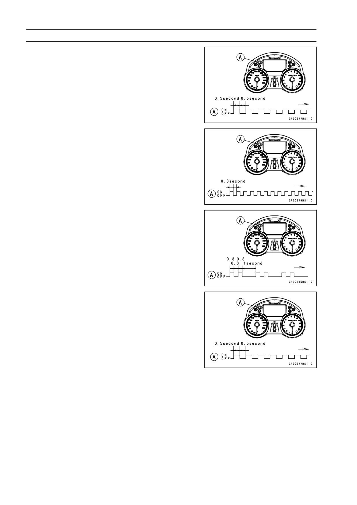
○The warning indicator light (LED) [A] blinks 2 times and
stops for 1 second and then repeats this cycle to indicate
successful registering of user key 1.
• Turn OFF and remove user key 1.
○The warning indicator light (LED) [A] blinks to display the
registration mode.
NOTE
○Turn off the ignition switch and wait for the period more
than 15 seconds. The registration mode automatically
ends and warning indicator light (LED) goes off.
○This procedure has , registered the master key and one
user key.
○Continue the procedure to program the second and
later keys.
• Insert the user key 2 to the ignition switch and turn it ON.
ELECTRICAL SYSTEM 16-89
Immobilizer System (Equipped Models)
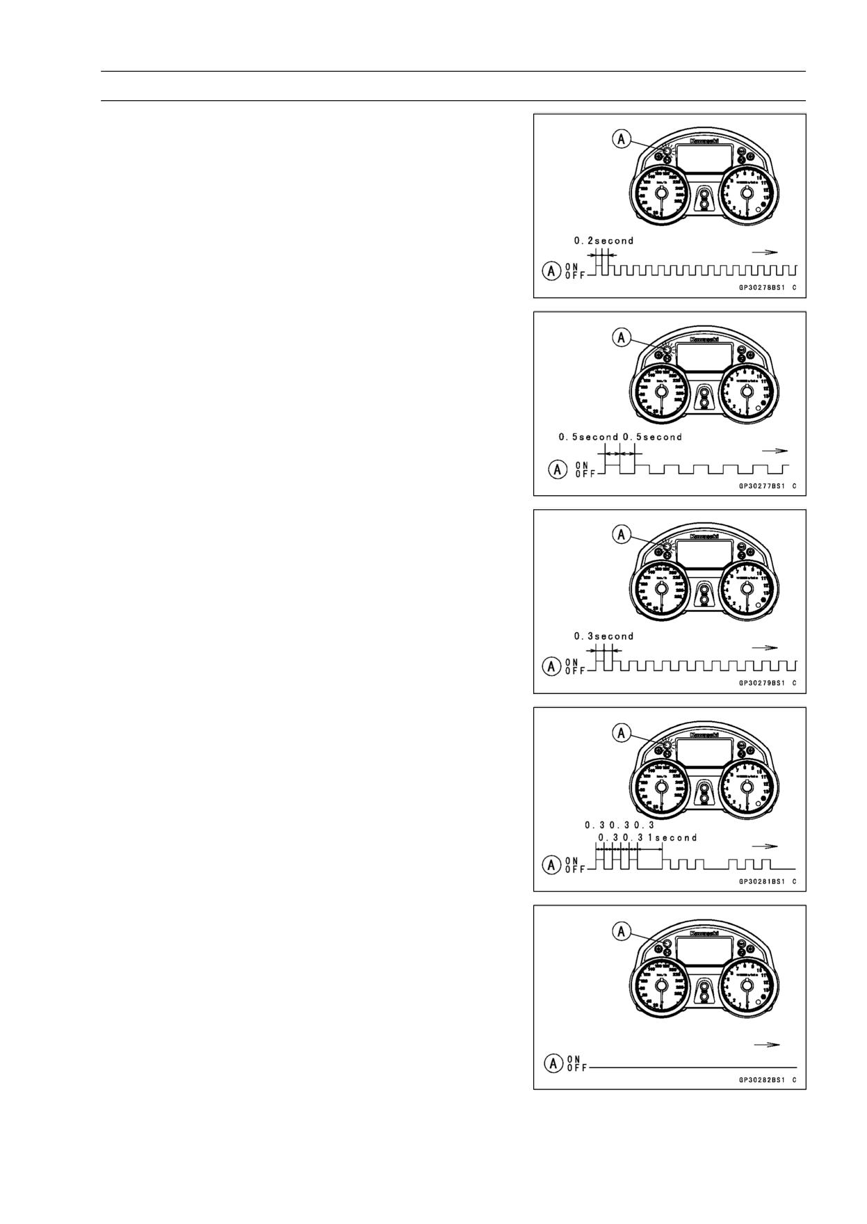
○If there is any problem in the registration, the warning
indicator light (LED) [A] blinks to display the collation error.
Immobilizer Amplifier Failure
When Registered User Key is Inserted.
User Key Collation Error
• The user key 2 is successfully registered in the ECU.
○The warning indicator light (LED) [A] blinks 3 times and
stops for 1 second and then repeat this cycle to indicate
successful programming of user key 2.
• Turn OFF the ignition switch and wait for period more than
15 seconds.
• The registration mode automatically ends.
• Warning indicator light (LED) [A] goes off.
16-90 ELECTRICAL SYSTEM
Immobilizer System (Equipped Models)
• Remove the key registration unit and connect the immo-
bilizer/Kawasaki diagnostic system connector.
NOTE
○Turn the ignition switch ON with the registered user key.
○Check that the engine can be started using all regis-
tered user keys.
• Install the new ignition switch and antenna.
Case 3: When the electric control unit (ECU) is faulty
and has to be replaced.
• Prepare a new ECU [A], current master key [B] and cur-
rent user keys [C].
NOTE
○The key registration unit is not required.
• Replace:
ECU [A] (see Immobilizer System Parts Replacement)
• Insert the current master key into the ignition switch and
turn it ON.
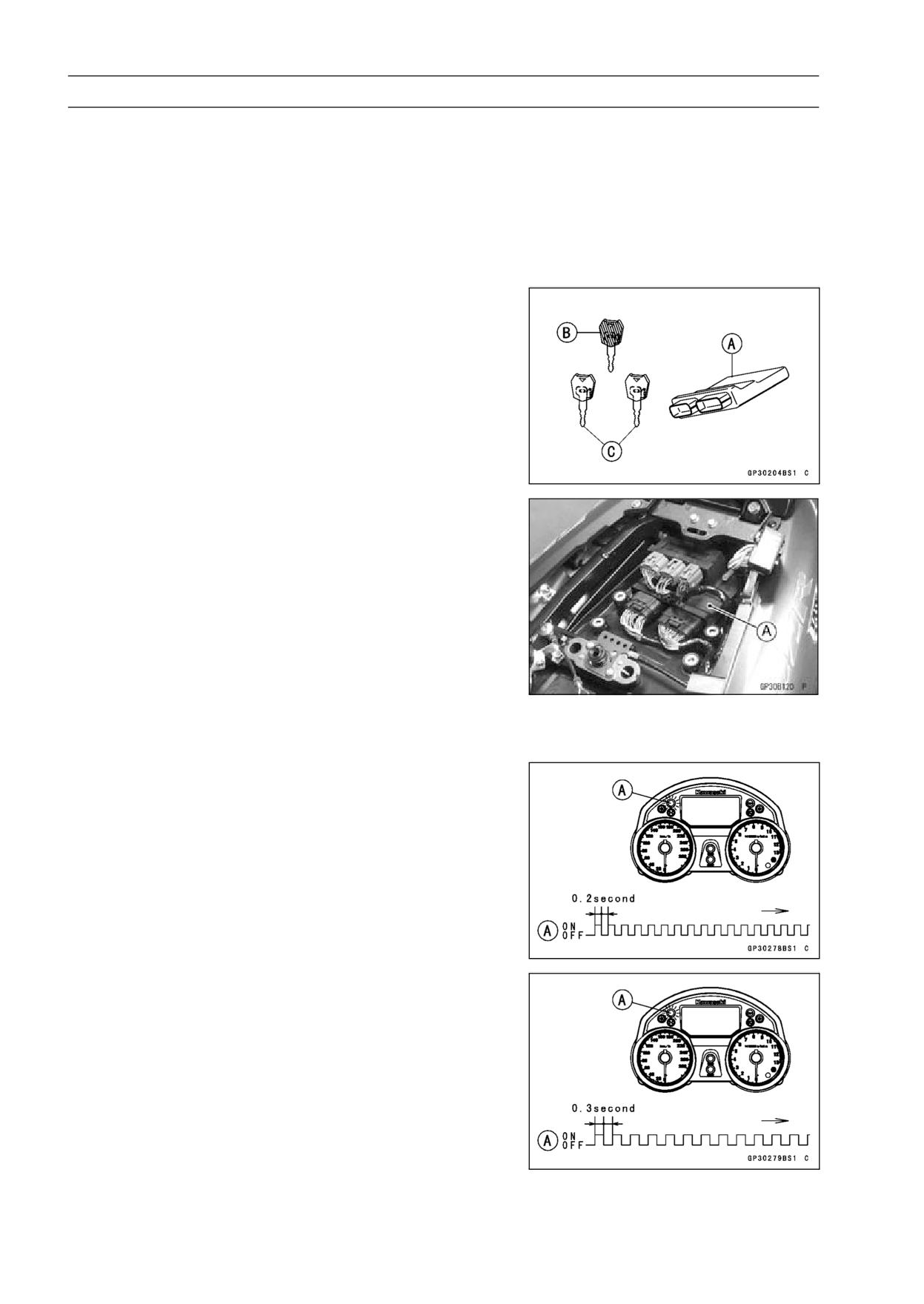
○If there is any problem in the registration, the warning
indicator light (LED) [A] blinks to display the collation error.
Immobilizer Amplifier Failure
Master Key Collation Error
ELECTRICAL SYSTEM 16-91
Immobilizer System (Equipped Models)
• The master key is registered in the ECU.
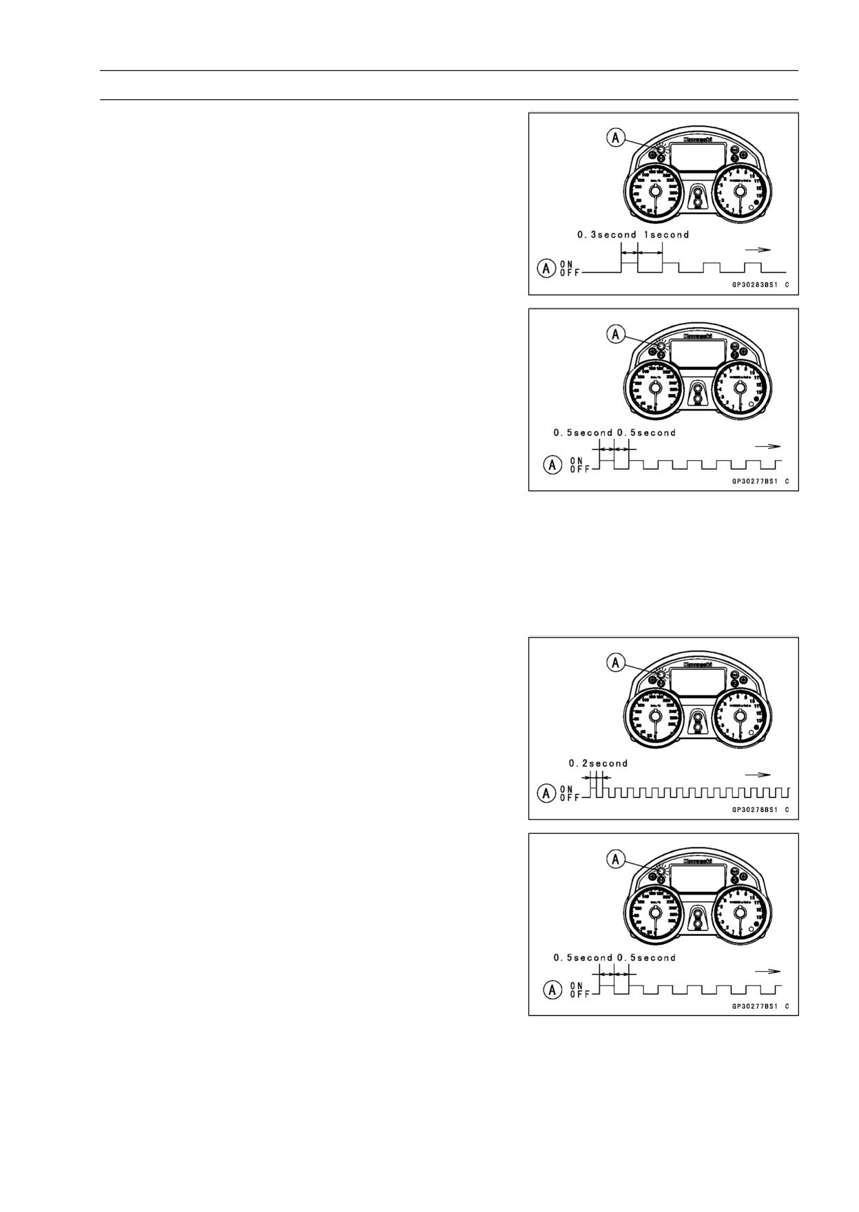
○The warning indicator light (LED) [A] blinks 1 time and
stops for 1 second and the repeats this cycle to indicate
successful registration of the master key.
• Turn OFF the master key and remove it.
○The warning indicator light (LED) [A] blinks to display the
registration mode.
NOTE
○Insert next key and turn ON within 15 seconds after pre-
vious key is turned off and removed otherwise registra-
tion mode will be ended and the warning indicator light
(LED) goes off.
○To return to the registration mode start the master key
verification procedure. This applies to all user key reg-
istration.
• Insert the user key 1 to the ignition switch and turn it ON.
NOTE
○Keep the other user keys away from the immobilizer
antenna.
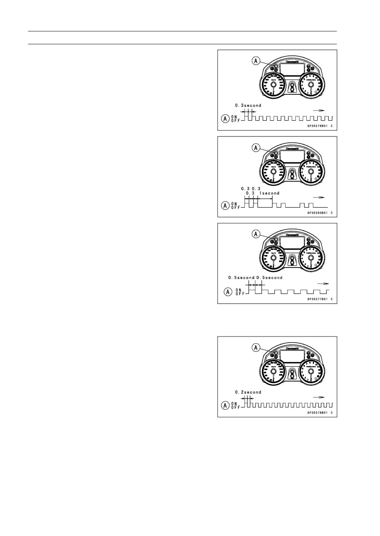
○If there is any problem in the registration, the warning
indicator light (LED) [A] blinks to display the collation error.
Immobilizer Amplifier Failure
When Registered User Key is Inserted.
16-92 ELECTRICAL SYSTEM
Immobilizer System (Equipped Models)
User Key Collation Error
• The user key 1 is registered in the ECU.
○The warning indicator light (LED) [A] blinks 2 times and
stops for 1 second and then repeats this cycle to indicate
successful registration of user key.
• Turn OFF and remove the user key 1.
○The warning indicator light (LED) [A] blinks to display the
registration mode codes.
NOTE
○Insert next key and turn ON within 15 seconds after pre-
vious key is turned off and removed otherwise registra-
tion mode will be ended and the warning indicator light
goes off.
○To return to the registration mode start the master key
verification procedure. This applies to all user key reg-
istration.
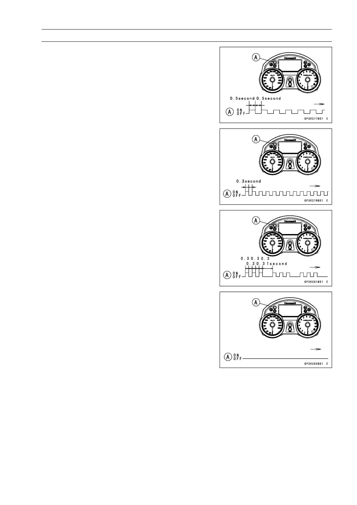
• Insert the user key 2 to the ignition switch and turn it ON.
○If there is any problem in the registration, the warning
indicator light (LED) [A] blinks to display the collation error
code.
Immobilizer Amplifier Failure
ELECTRICAL SYSTEM 16-93
Immobilizer System (Equipped Models)
When Registered User Key is Inserted.
User Key Collation Error
• The user key 2 is registered in the ECU.
○The warning indicator light (LED) [A] blinks 3 times and
stops for 1 second and then repeats this cycle to indicate
successful registration of user key 2.
• Turn OFF the ignition switch and wait for period more than
15 seconds.
• The registration mode automatically ends.
• Warning indicator light (LED) [A] goes off.
NOTE
○Turn the ignition switch ON with the registered user key.
○Check that the engine can be started using all regis-
tered user keys.
Case 4: When master key is faulty or lost.
The master key replacement is considered very rare case.
However if it is required, the following is necessary.
NOTE
○The ECU must be replaced with a new one because the
master key code that is registered in the current ECU
can not be rewritten.
16-94 ELECTRICAL SYSTEM
Immobilizer System (Equipped Models)
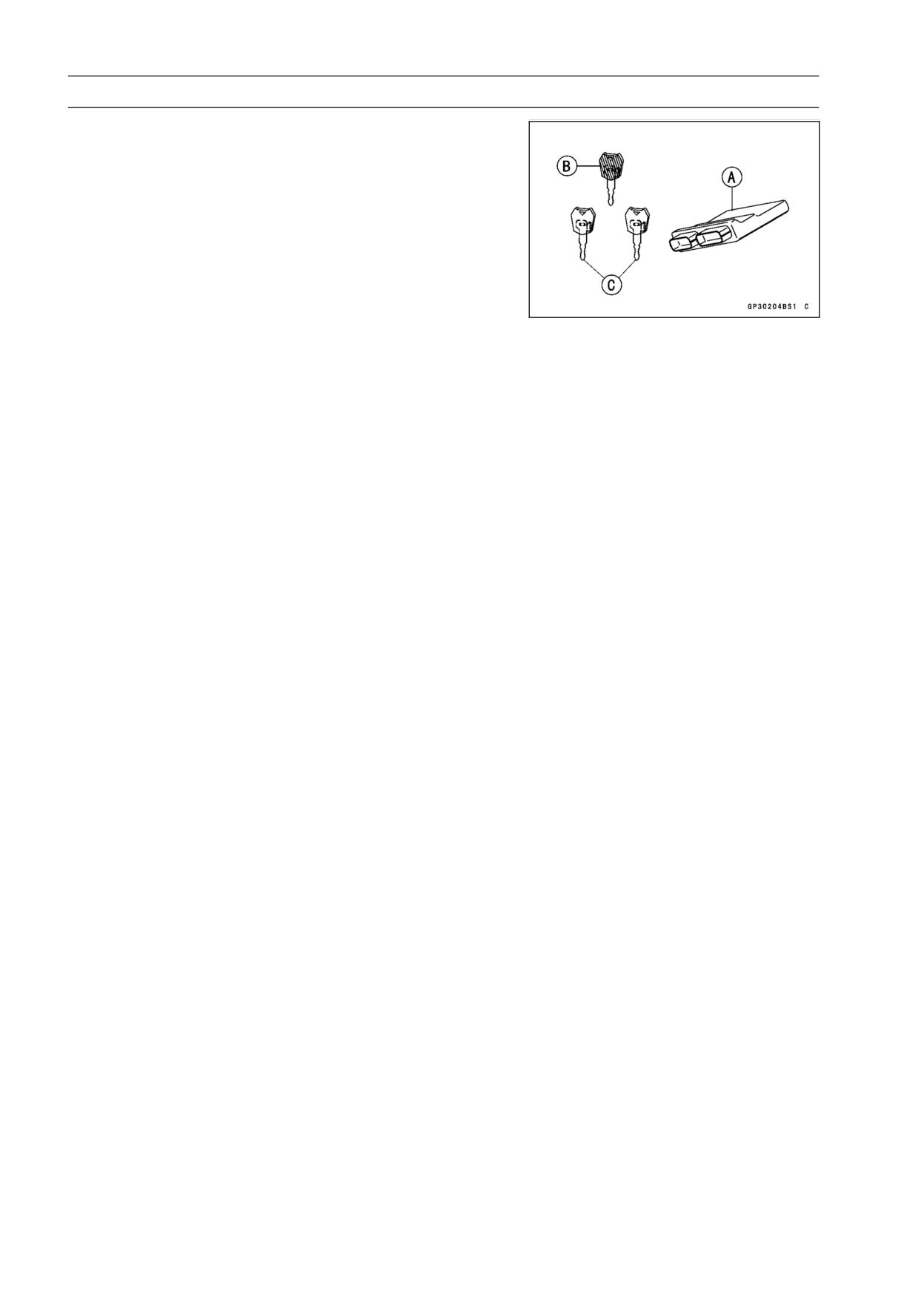
• Prepare a new ECU [A], new master key [B] and current
user keys [C].
NOTE
○The key registration unit is not required.
○The key registration process is same as the electric con-
trol unit replacement.
Case 5: When replacing the antenna.
• Prepare a new antenna.
• Refer to the Immobilizer System Parts Replacement.
NOTE
○No key registration is required.
ELECTRICAL SYSTEM 16-95
Immobilizer System (Equipped Models)
All Keys Initial Registration Flow Chart
16-96 ELECTRICAL SYSTEM
Immobilizer System (Equipped Models)
Immobilizer System Parts Replacement
Immobilizer Antenna
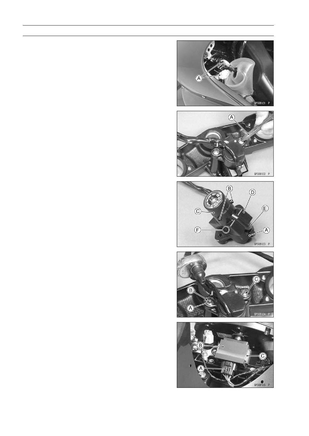
• Remove the left inner cover (see Inner Cover Removal in
the Frame chapter).
• Disconnect the lead connectors [A].
• Remove:
Steering Stem Head (see Stem, Stem Bearing Removal
in the Steering chapter)
• Using a small chisel or punch [A], turn out the Torx bolts.
• Cut the band [A].
• Remove the screw [B].
• Remove the antenna [C] with the cover [D].
○Pull the lower parts [E] of the cover outside to clear the
projection [F] of the ignition switch.
• Tighten a new Torx bolt [A] until the bolt head [B] is broken.
[C] Broken Head of Other Side
• Run the leads correctly (see Cable, Wire, and Hose Rout-
ing section in the Appendix chapter).
Immobilizer Amplifier Replacement
• Remove the windshield (see Windshield Removal in the
Frame chapter).
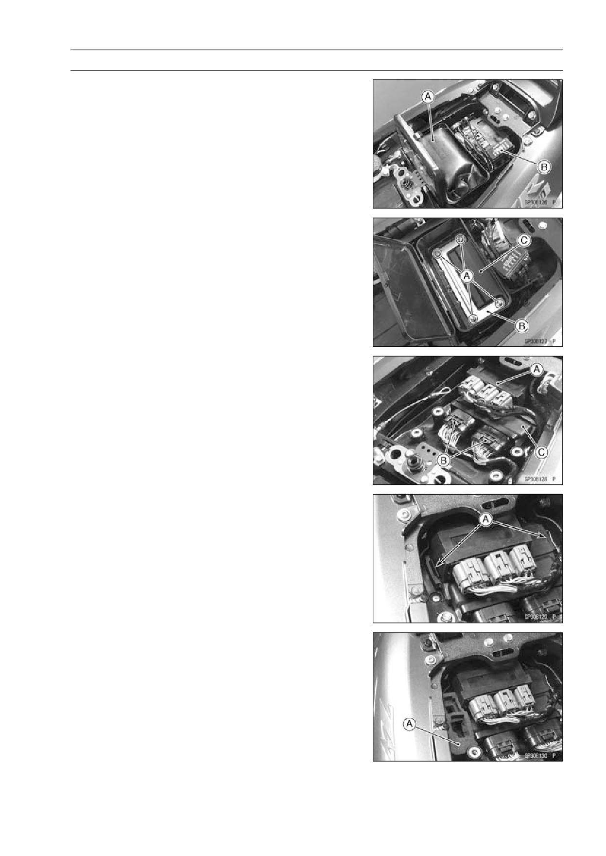
• Disconnect the connector [A].
• Remove the amplifier [B] from the bracket [C].
ELECTRICAL SYSTEM 16-97
Immobilizer System (Equipped Models)
ECU (Electric Control Unit) Replacement (for
Immobilizer Models)
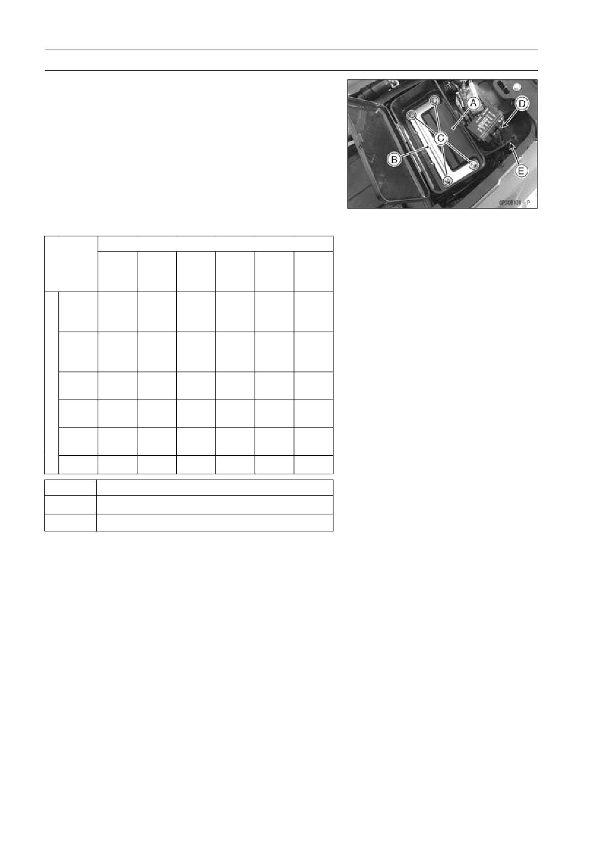
• Remove:
Seat (see Seat Removal in the Frame chapter)
Tool Kit [A]
Fuse Box [B]
• Using small chisel or other suitable tool, cut off the screws
[A].
• Remove:
Plate [B]
Tool Kit Case [C]
• Remove:
Relay Box [A]
ECU Connectors [B]
ECU [C]
• Install:
ECU Connectors
Relay Box
• Insert the slits of the rubber protector to the projections
[A] of the rear fender front.
• Install:
Connector Holder [A]
16-98 ELECTRICAL SYSTEM
Immobilizer System (Equipped Models)
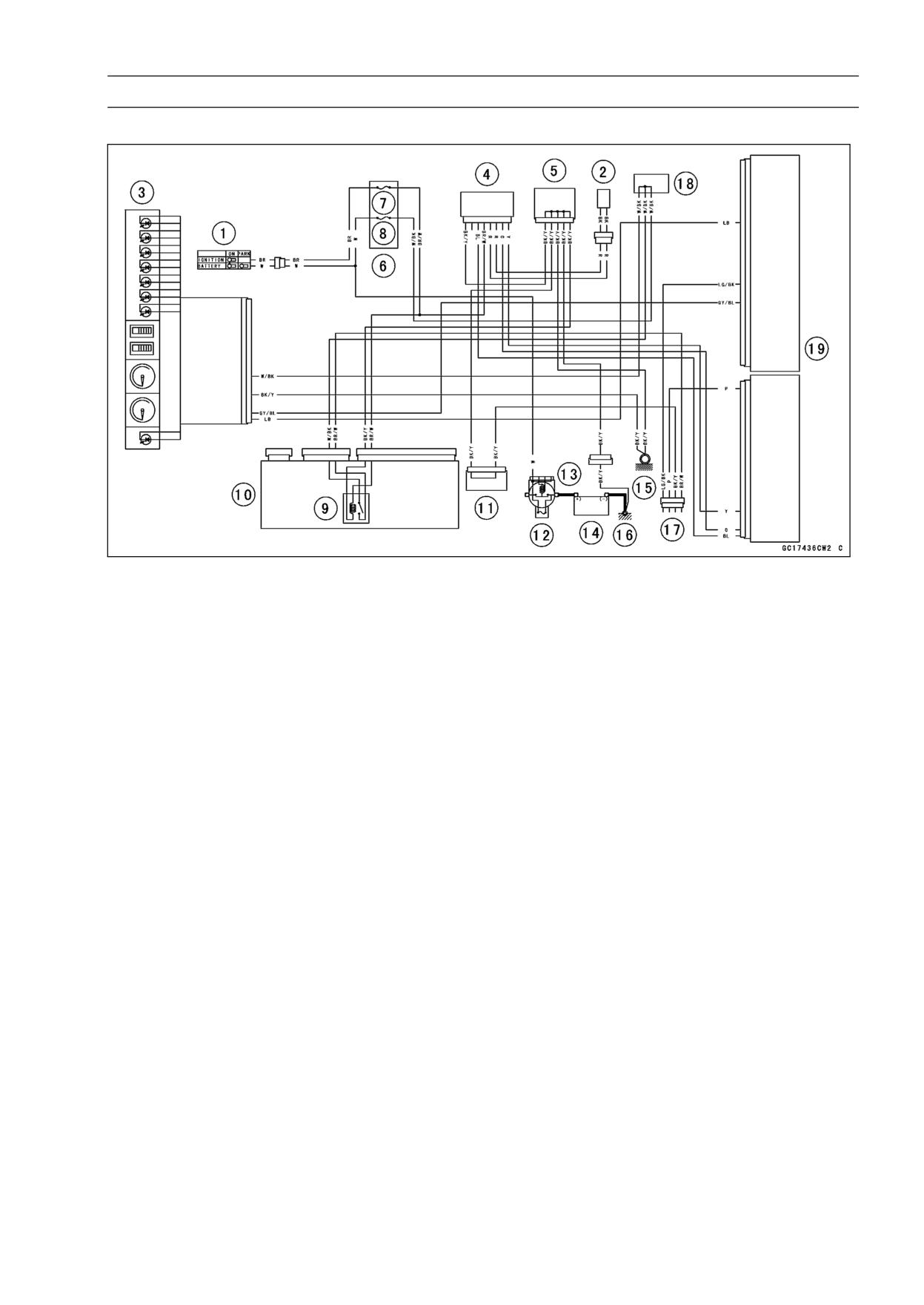
• Install:
Tool Kit Case [A]
Plate [B]
• Tighten the new Kawasaki genuine screws [C] of which
threads are coated with locking agent.
• Insert the stopper [D] of the fuse box into the groove [E]
of the tool kit case.
Immobilizer Relational Parts Replacement Chart
Failed or Lost Part
Master
User
Ignition
An-
Ampli-
Key
Key
ECU
Switch
tenna
fier
(Red)
(Black)
Master
Key
•
(Red)
User
Key
○
•
(Black)
Ignition
*
Switch
•
An-
tenna
•
Ampli-
fier
•
ECU
○
•
*
Replacement Part
• MainReplacementPart
○
Additional Replacement Part
Immobilizer System Inspection
• Refer to the Immobilizer Amplifier and Blank Key Detec-
tion section in Fuel System (DFI) chapter (see Immobilizer
Amplifier (Service Code 35) section in the Fuel System
(DFI) chapter).
ELECTRICAL SYSTEM 16-99
Immobilizer System (Equipped Models)
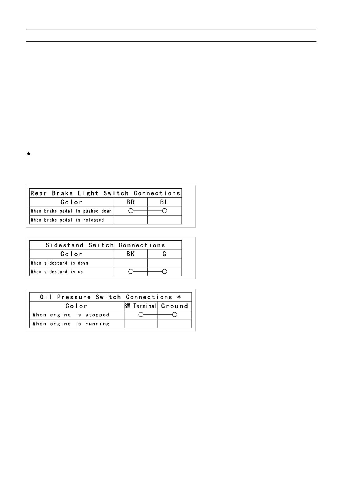
Immobilizer System Circuit
1. Ignition Switch
2. Immobilizer Antenna
3. Meter Unit
4. Immobilizer Amplifier
5. Joint Connector 1
6. Fuse Box 2
7. ECU Fuse 15 A
8. Ignition Fuse 10 A
9. Main Relay
10. Relay Box
11. Joint Connector 2
12. Main Fuse 30 A
13. Starter Relay
14. Battery 12 V 14 Ah
15. Frame Ground 1
16. Frame Ground 2
17. Immobilizer/Kawasaki Diagnostic System Connector
18. Water-proof Joint 1
19. ECU
16-100 ELECTRICAL SYSTEM
Switches and Sensors
Brake Light Timing Inspection
• Refer to the Brake Light Switch Operation Inspection in
the Periodic Maintenance chapter.
Brake Light Timing Adjustment
• Refer to the Brake Light Switch Operation Inspection in
the Periodic Maintenance chapter.
Switch Inspection
• Using a hand tester, check to see that only the con-
nections shown in the table have continuity (about zero
ohms).
○For the switch housings and the ignition switch, refer to
the tables in the Wiring Diagram.
If the switch has an open or short, repair it or replace it
with a new one.
Special Tool - Hand Tester: 57001-1394
Rear Brake Light Switch Connections
Sidestand Switch Connections
Oil Pressure Switch Connections*
*: Engine lubrication system is in good condition.
ELECTRICAL SYSTEM 16-101
Switches and Sensors
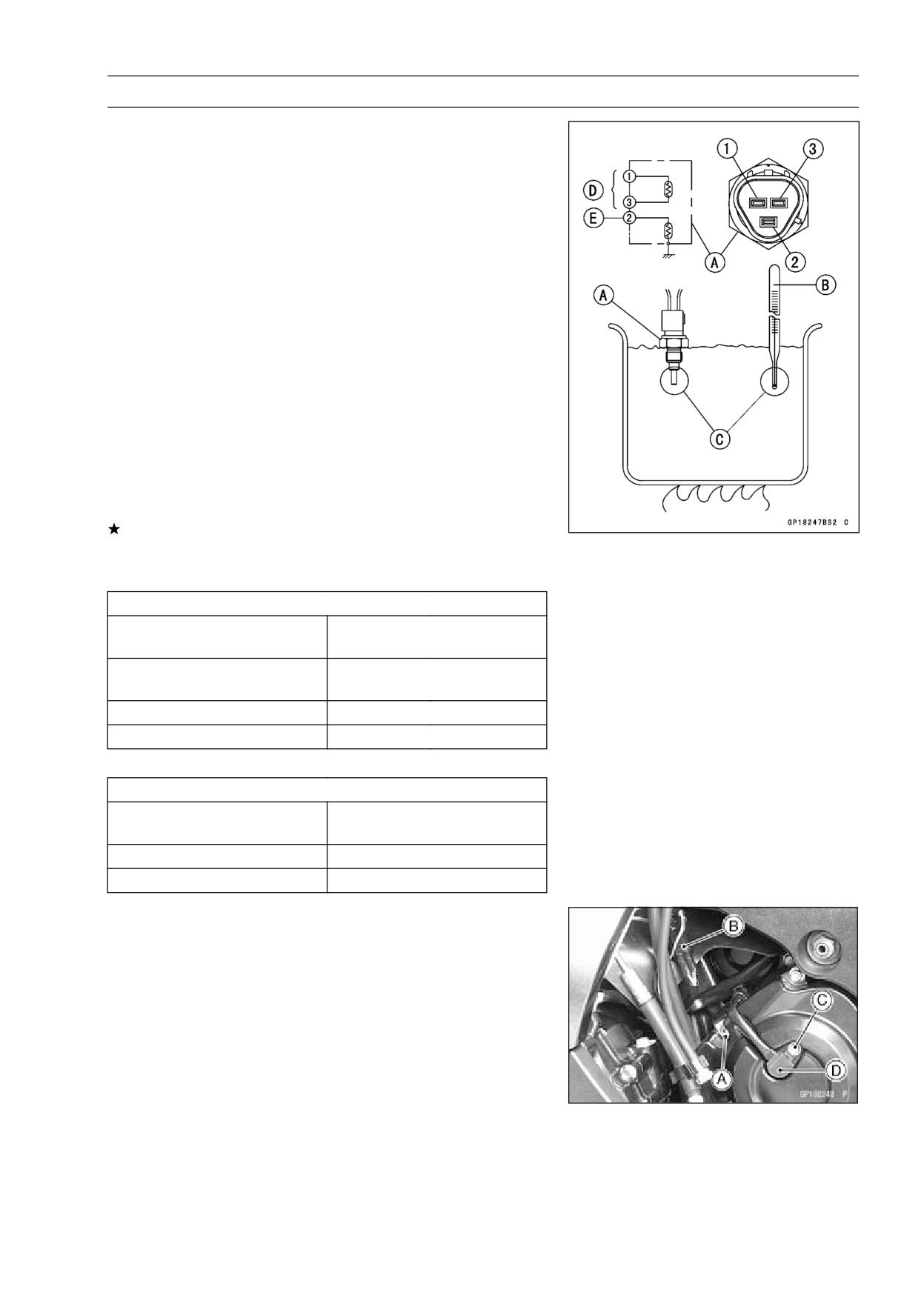
Water Temperature Sensor Inspection
• Remove the water temperature sensor (see Removal/In-
stallation in the Fuel System (DFI) chapter).
• Suspend the sensor [A] in a container of coolant so that
the threaded portion is submerged.
• Suspend an accurate thermometer [B] with temperature
sensing portions [C] located in almost the same depth.
NOTE
○The sensor and thermometer must not touch the con-
tainer side or bottom.
• Place the container over a source of heat and gradu-
ally raise the temperature of the coolant while stirring the
coolant gently.
• Using the hand tester, measure the internal resistance of
the sensor.
○The sensor sends electric signals to the ECU and coolant
temperature gauge in the meter unit.
○Measure the resistance across the terminals and the body
(for the gauge) at the temperatures shown in the table.
If the hand tester does not show the specified values, re-
place the sensor.
Water Temperature Sensor
Resistance for ECU [D]
Resistance (kΩ)
Temperature
(Terminal [1]-[3])
+0.115
20°C (68°F)
2.46
-0.143
80°C (176°F)
0.32 ±0.011
110°C (230°F)
0.1426 ±0.0041
Resistance for Water Temperature Gauge [E]
Resistance (Ω)
Temperature
(Terminal [2]-Body)
50°C (122°F)
210 ±40
120°C (248°F)
21.2 ±1.5
Speed Sensor Removal
• Loosen the bolt [A].
• Disconnect the speed sensor lead connector [B].
• Remove:
Bolt [C]
Speed Sensor [D]
Speed Sensor Installation
• Apply a non-permanent locking agent to the sensor bolt.
• Install the speed sensor.
Torque - Speed Sensor Bolt: 3.9 N·m (0.40 kgf·m, 35 in·lb)
16-102 ELECTRICAL SYSTEM
Switches and Sensors
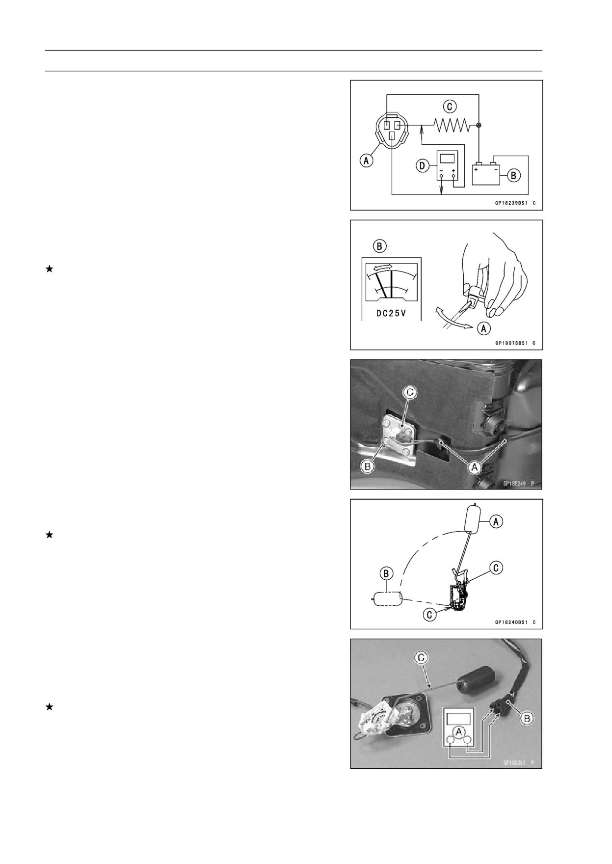
Speed Sensor Inspection
• Remove the speed sensor (see Speed Sensor Removal).
• Connect the speed sensor lead connector [A] with the bat-
tery [B], 10 kΩ resistor [C] and hand tester [D] as shown.
• Set the tester to the DC 25 V range.
Special Tool - Hand Tester: 57001-1394
• Trace [A] each side of the speed sensor surface with the
screw driver.
○Then the tester indicator should flick [B].
If the tester indicator does not flick, replace the speed
sensor.
Fuel Level Sensor Inspection
• Remove the fuel tank (see Fuel Tank Removal in the Fuel
System (DFI) chapter).
• Open the clamps [A].
• Remove:
Bolts [B]
Fuel Level Sensor [C]
• Check that the float moves up and down smoothly without
binding. It should go down under its own weight.
If the float does not move smoothly, replace the sensor.
Float in Full Position [A]
Float in Empty Position [B]
Float Arm Stoppers [C]
• Using the hand tester [A], measure the resistance across
the terminals in the fuel level sensor lead connector [B].
Special Tools - Hand Tester: 57001-1394
Needle Adapter Set: 57001-1457
If the tester readings are not as specified, or do not
change smoothly according as the float moves up and
down, replace the sensor.
Fuel Level Sensor Resistance
Standard: Full position [C]: 9 ∼ 11 Ω
Empty position: 213 ∼ 219 Ω
ELECTRICAL SYSTEM 16-103
Switches and Sensors
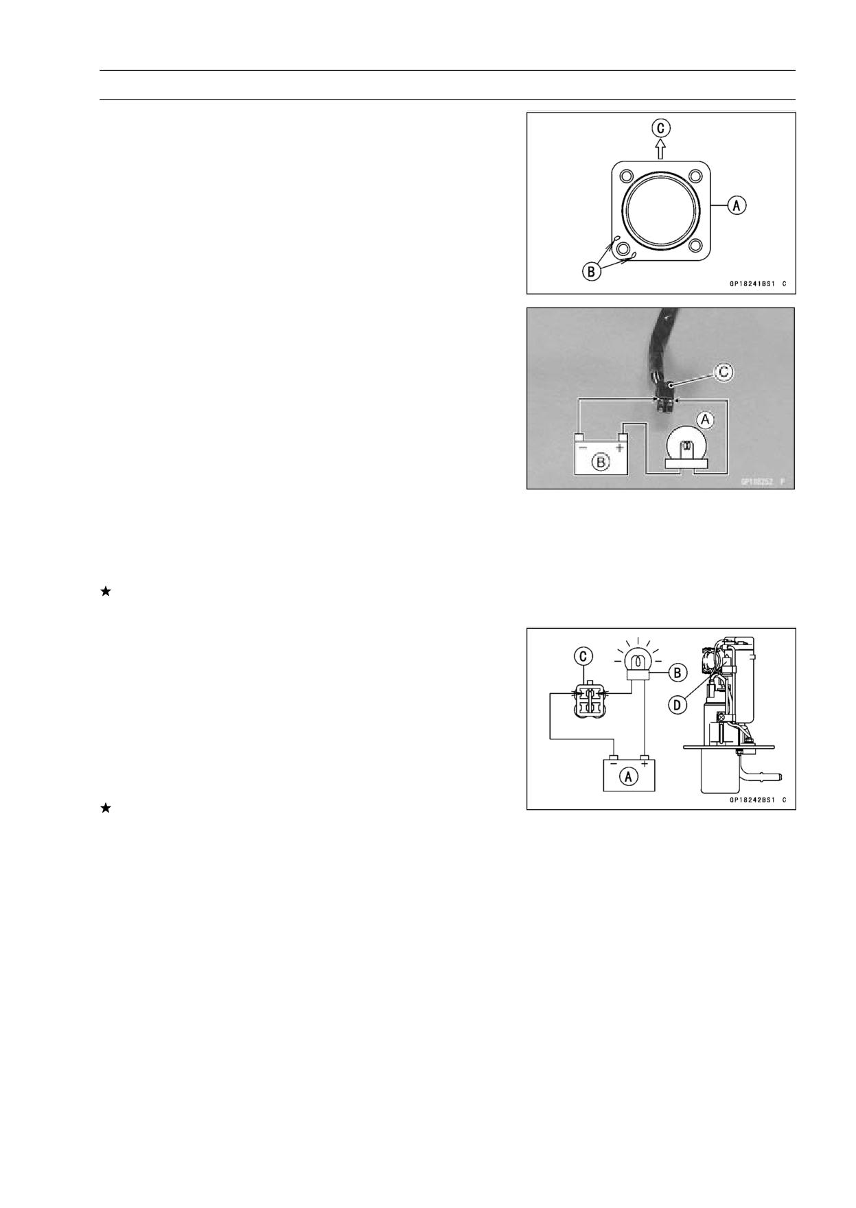
• Install a new gasket [A] on the fuel level sensor as shown.
Hollows [B]
Front [C]
• Apply a non-permanent locking agent to the threads of
the level sensor bolts and tighten it.
Torque - Fuel Level Sensor Bolts: 6.9 N·m (0.70 kgf·m, 61
in·lb)
Fuel Reserve Switch Inspection
• Fill the fuel tank with fuel.
• Close the fuel tank cap surely.
• Remove the fuel tank (see Fuel Tank Removal in the Fuel
System (DFI) chapter).
• Connect the test light [A] (12 V 3.4 W bulb in a socket with
leads) and the 12 V battery [B] to the fuel pump connector
[C].
Connections
Battery (+) → 12 V 3.4 W Bulb (one side)
12 V 3.4 W Bulb (other side) → BK/R Lead Terminal
Battery (-) → BK/W Lead Terminal
Special Tool - Needle Adapter Set: 57001-1457
If the test light turn on, the reserve switch is defective.
Replace the fuel pump.
• Remove the fuel pump (see Fuel Pump Removal in the
Fuel System (DFI) chapter).
• Connect the test light (12 V 3.4 W bulb in a socket with
leads) and the 12 V battery to the fuel pump connector as
shown.
12 V Battery [A]
Test Light [B]
Fuel Pump Connector [C]
Fuel Reserve Switch [D]
If the test light doesn’t light, replace the fuel pump.
NOTE
○It may take a long time to turn on the test light in case
that the fuel reserve switch is inspected just after the
fuel pump is removed. Leave the fuel reserve switch
with leads for inspection connected for few minutes.
16-104 ELECTRICAL SYSTEM
Switches and Sensors
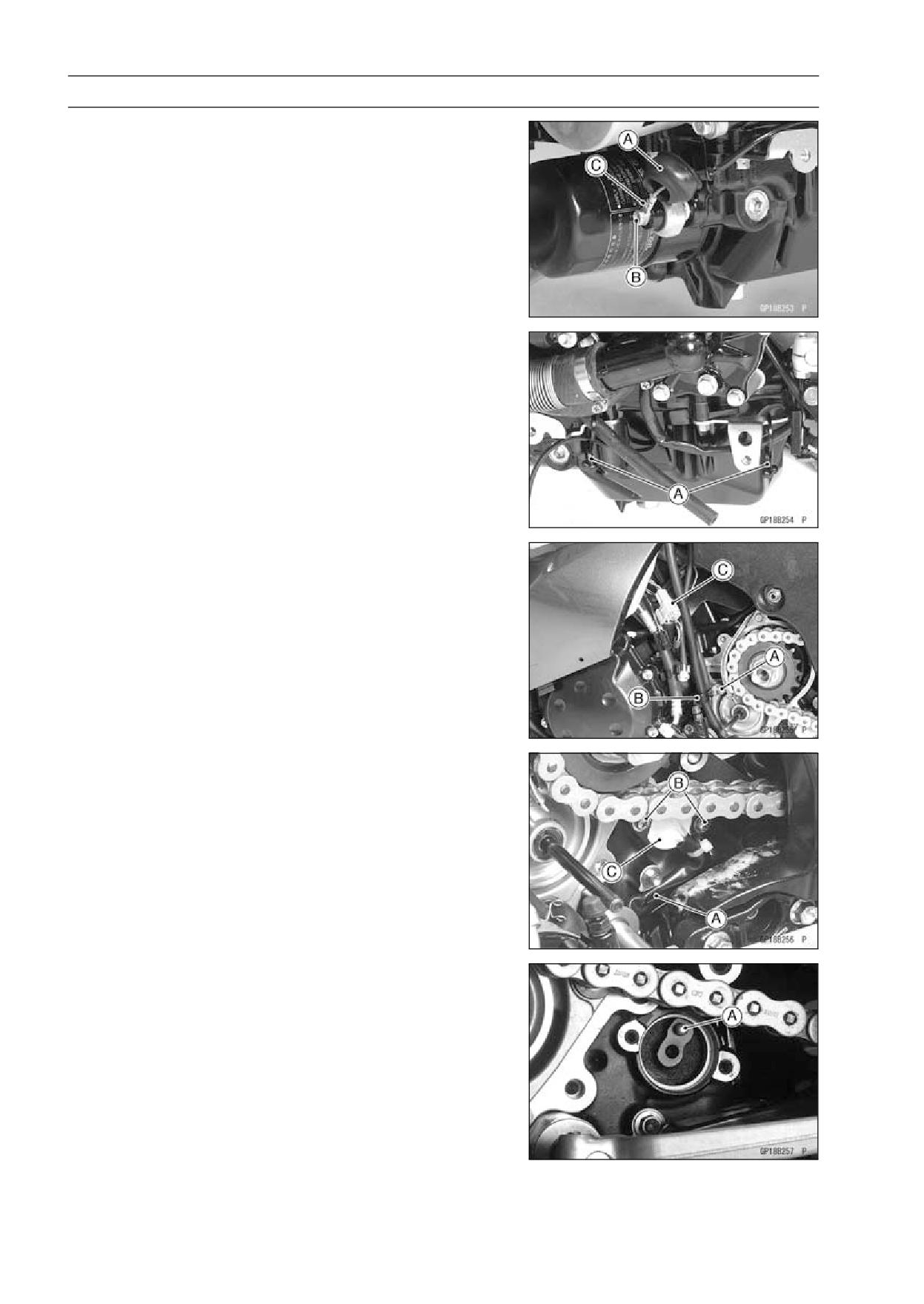
Gear Position Switch Removal
• Remove the lower fairings (see Lower Fairing Removal in
the Frame chapter).
• Slide out the rubber boot [A].
• Loosen the oil pressure switch terminal bolt [B], and re-
move the switch lead [C].
• Open the clamps [A].
• Remove:
Engine Sprocket Cover (see Engine Sprocket Removal
in the Final Drive chapter)
Bolt [A]
Clamp [B]
• Disconnect the oil pressure switch/gear position switch
lead connector [C].
• Open the clamp [A].
• Remove:
Screws [B]
Gear Position Switch [C]
• Remove the pin [A] and spring from the shift drum.
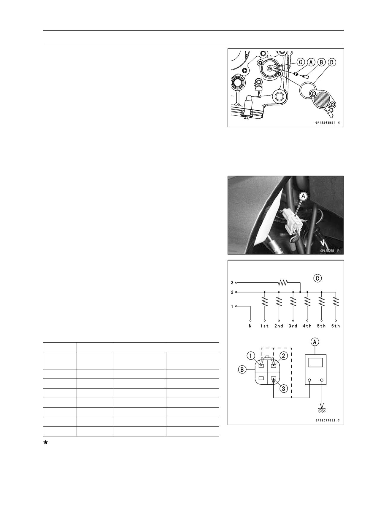
ELECTRICAL SYSTEM 16-105
Switches and Sensors
Gear Position Switch Installation
• Securely place the spring [A] and pin [B] into the hole [C]
of the shift drum.
• Apply grease to the new O-ring [D].
• Apply a non-permanent locking agent to the gear position
switch screws.
• Tighten:
Torque - Gear Position Switch Screws: 3.0 N·m (0.31 kgf·m,
27 in·lb)
Gear Position Switch Lead Clamp Bolt: 9.8 N·m
(1.0 kgf·m, 87 in·lb)
• Run the gear position switch and oil pressure switch lead
correctly (see Cable, Wire, and Hose Routing section in
the Appendix chapter).
• Install the removed parts (see appropriate chapters).
Gear Position Switch Inspection
NOTE
○Be sure the transmission mechanism is good condition.
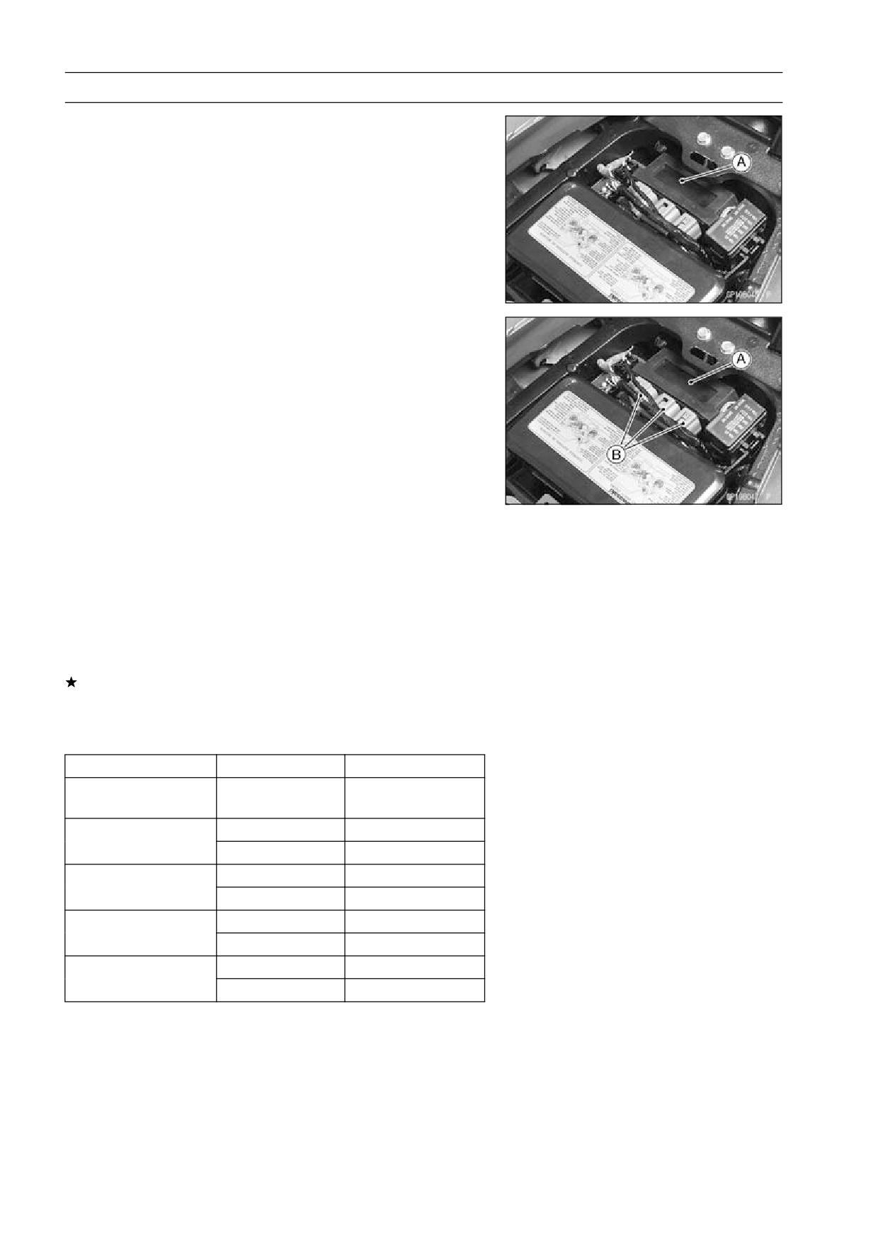
• Disconnect the connector [A].
• Set the hand tester [A] to the 1 kΩ or × 100 Ω range and
connect it to the terminals in the oil pressure switch/gear
position switch lead connector [B] and ground.
[C] Internal Circuit
[1] Light Green Lead
[2] Green/Red Lead
[3] Black Lead
Special Tool - Hand Tester: 57001-1394
Gear Position Switch Resistance
kΩ
Connections
Gear
[1]-Ground
[2]-Ground
[3]-Ground
Position
Neutral
about 0
-
-
1st
-
3.00 ∼ 3.32
11.63 ∼ 12.87
2nd
-
1.70 ∼ 1.89
10.33 ∼ 11.44
3rd
-
1.07 ∼ 1.19
9.70 ∼ 10.74
4th
-
0.695 ∼ 0.769
9.32 ∼ 10.32
5th
-
0.430 ∼ 0.476
9.06 ∼ 10.03
6th
-
0.248 ∼ 0.274
8.89 ∼ 9.81
If the tester reading is not as specified, replace the gear
position switch with a new one.
16-106 ELECTRICAL SYSTEM
Relay Box
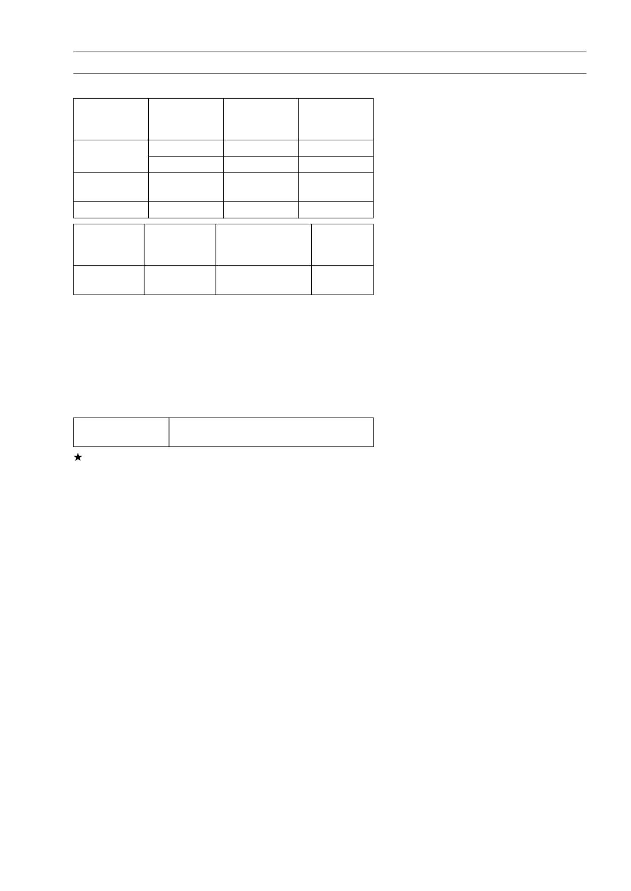
The relay box [A] has relays and diodes. The relays and
diodes can not be removed.
Relay Box Removal
• Remove the seat (see Seat Removal in the Frame chap-
ter).
• Take out the relay box [A] and disconnect the connectors
[B].
Relay Circuit Inspection
NOTE
○The ECU main relay function is included in the ECU.
• Remove the relay box (see Relay Box Removal).
• Check conductivity of the following numbered terminals
by connecting the hand tester and one 12 V battery to the
relay box as shown (see Relay Box Internal Circuit).
If the tester does not read as specified, replace the relay
box.
Relay Circuit Inspection (with the battery disconnected)
Tester Connection
Tester Reading (Ω)
Headlight Circuit
1-3
∞
Relay
6-7
∞
Main Relay
4-5
Not ∞*
7-8
∞
Fuel Pump Relay
9-10
Not ∞*
11-16
∞
Starter Circuit Relay
11-12
∞
17-20
∞
Fan Relay
18-19
Not ∞*
*: The actual reading varies with the hand tester used.
ELECTRICAL SYSTEM 16-107
Relay Box
Relay Circuit Inspection (with the battery connected)
Battery
Tester
Tester
Connection
Connection
Reading (Ω)
(+)
(-)
2-11
1-3
0
Main Relay
4-5
7-6
0
Fuel Pump
9-10
7-8
0
Relay
Fan Relay
18-19
17-20
0
Battery
Tester Connection
Tester
Connection
DC 25 V Range
Reading (V)
(+)
(-)
Starter Circuit
Battery
16-12
11-12
Relay
Voltage
(+): Apply positive lead.
(-): Apply negative lead.
Diode Circuit Inspection
• Remove the relay box (see Relay Box Removal).
• Check conductivity of the following pairs of terminals (see
Relay Box Internal Circuit).
Diode Circuit Inspection
1-11, 2-11, 12-13, 12-15, 12-16, 13-14,
Tester Connection
13-15
The resistance should be low in one direction and more
than ten times as much in the other direction. If any diode
shows low or high in both directions, the diode is defective
and the relay box must be replaced.
NOTE
○The actual meter reading varies with the meter or tester
used and the individual diodes, but generally speaking,
the lower reading should be from zero to one half the
scale.
16-108 ELECTRICAL SYSTEM
Relay Box
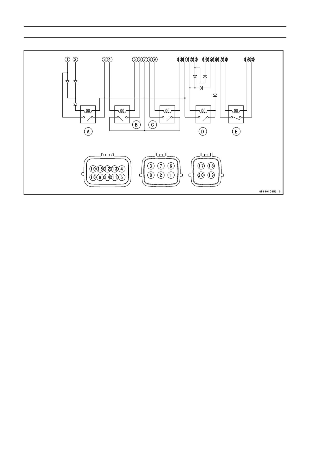
Relay Box Internal Circuit
A. Headlight Circuit Relay
B. Main Relay
C. Fuel Pump Relay
D. Starter Circuit Relay
E. Fan Relay
ELECTRICAL SYSTEM 16-109
Fuse
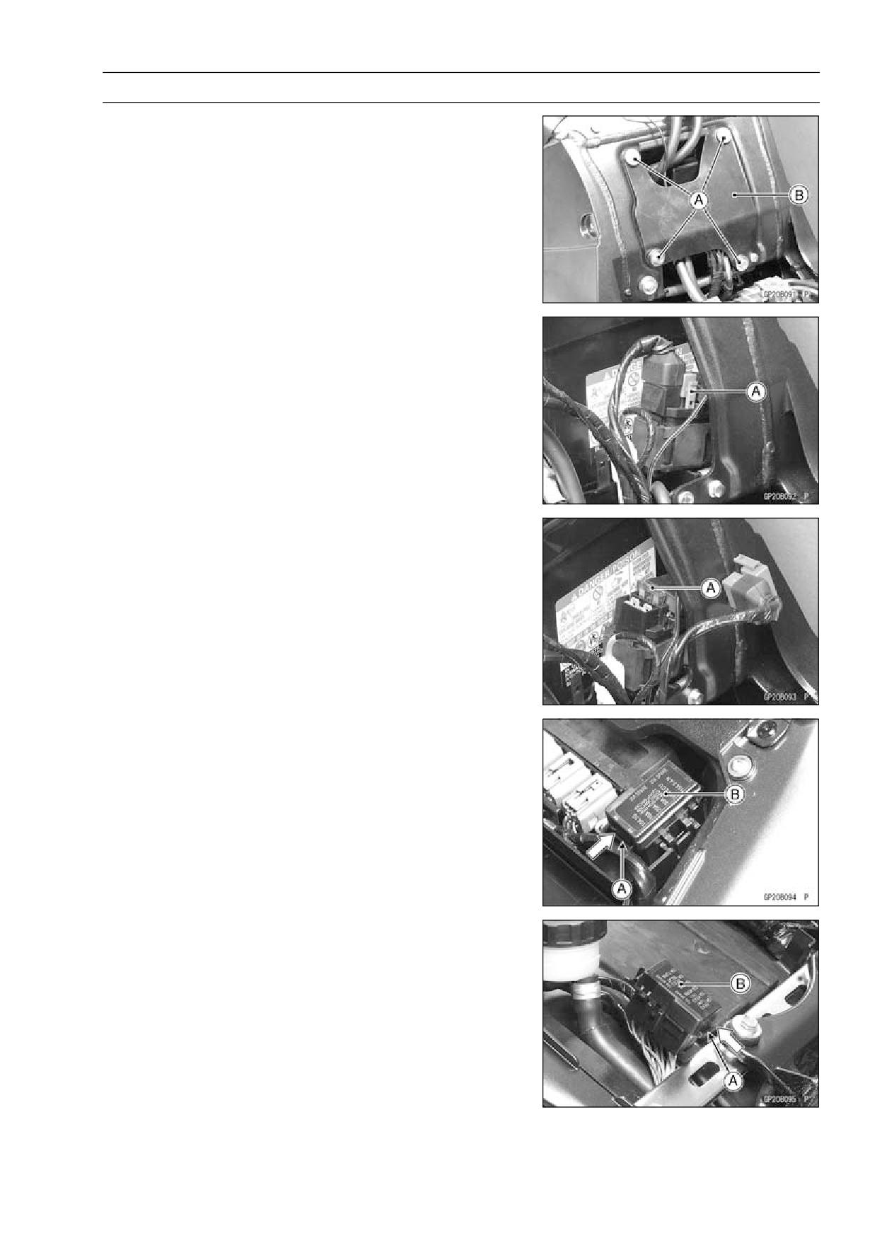
30 A Main Fuse Removal
• Remove:
Fuel Tank (see Fuel Tank Removal in the Fuel System
(DFI) chapter)
Bolts [A]
Cover [B]
• Disconnect the 30 A main fuse connector [A].
• Pull out the main fuse [A] from the starter relay with needle
nose pliers.
Fuse Box Fuse Removal
• Remove the seat (see Seat Removal in the Frame chap-
ter).
• Unlock the hook [A] to lift up the lid [B].
16-110 ELECTRICAL SYSTEM
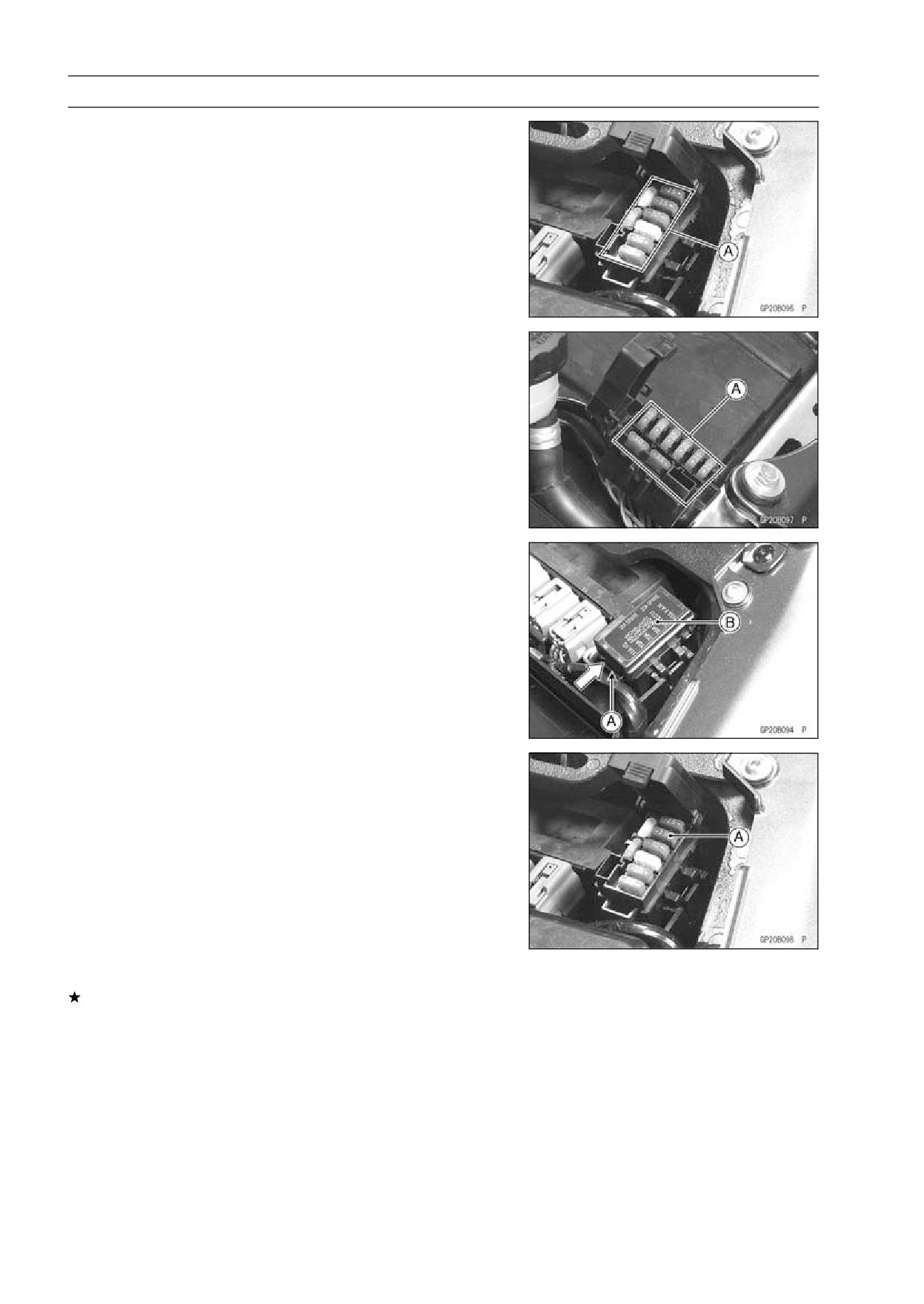
Fuse
• Pull the fuses [A] straight out of the fuse box with needle
nose pliers.
15 A ECU Fuse Removal
• Remove the seat (see Seat Removal in the Frame chap-
ter).
• Unlock the hook [A] to lift up the lid [B].
• Pull out the ECU fuse [A] from the fuse box.
Fuse Installation
If a fuse fails during operation, inspect the electrical sys-
tem to determine the cause, and then replace it with a
new fuse of proper amperage.
• Install the fuse box fuses on the original position as spec-
ified on the lid.
ELECTRICAL SYSTEM 16-111
Fuse
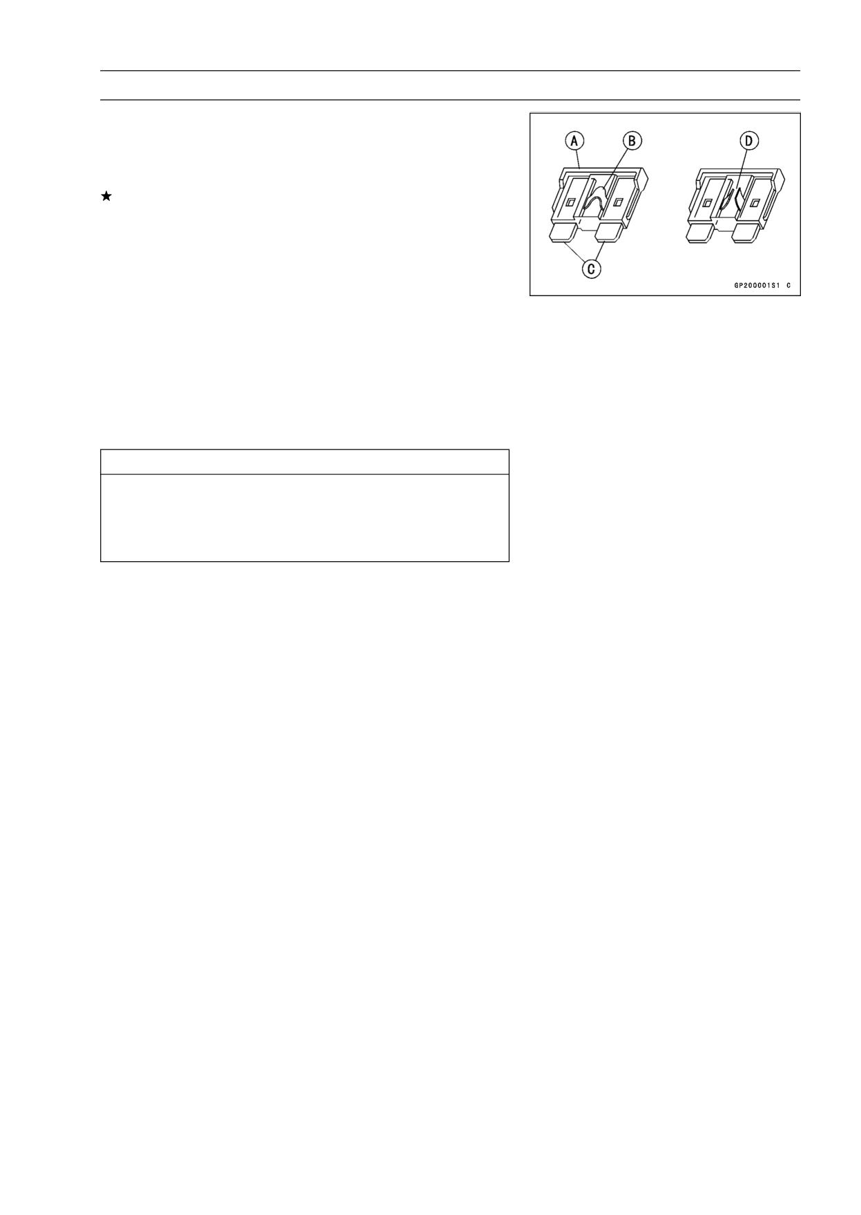
Fuse Inspection
• Remove the fuse (see 30 A Main/Fuse Box/15 A ECU
Fuse Removal).
• Inspect the fuse element.
If it is blown out, replace the fuse. Before replacing a
blown fuse, always check the amperage in the affected
circuit. If the amperage is equal to or greater than the
fuse rating, check the wiring and related components for
a short circuit.
Housing [A]
Fuse Element [B]
Terminals [C]
Blown Element [D]
NOTE
○A mass current flows to the battery according to the
state of the battery which needs refreshing charge when
the engine is turned causing main fuse blown out.
CAUTION
When replacing a fuse, be sure the new fuse
matches the specified fuse rating for that circuit.
Installation of a fuse with a higher rating may cause
damage to wiring and components.
APPENDIX 17-1
Appendix
Table of Contents
Cable, Wire, and Hose Routing
17-2
Troubleshooting Guide
17-52
17
17-2 APPENDIX
Cable, Wire, and Hose Routing
APPENDIX 17-3
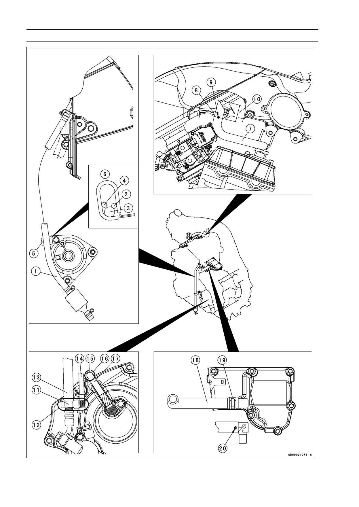
Cable, Wire, and Hose Routing
1. Air Cleaner Drain Hose
2. Gear Position Switch Lead
3. Air Bleeder Hose for Water Pump
4. Sidestand Switch Lead
5. Clamp
6. Clamp the leads and hose as shown in the figure.
7. Tube
8. Grommet
9. Install the air switching valve hose until white paint is half hidden level.
10. Approx. 41 mm (0.02 in.)
11. Clamp
12. First, put the clamp to the adjuster screw position of shown in the figure, next fix to the clutch
hose.
13. Clutch Hose
14. Idle Adjusting Screw
15. Clamp
16. Clamp the speed sensor lead.
17. Speed Sensor Lead
18. Breather Tube
19. Clamp
20. Align the white paint and the end of the plate.
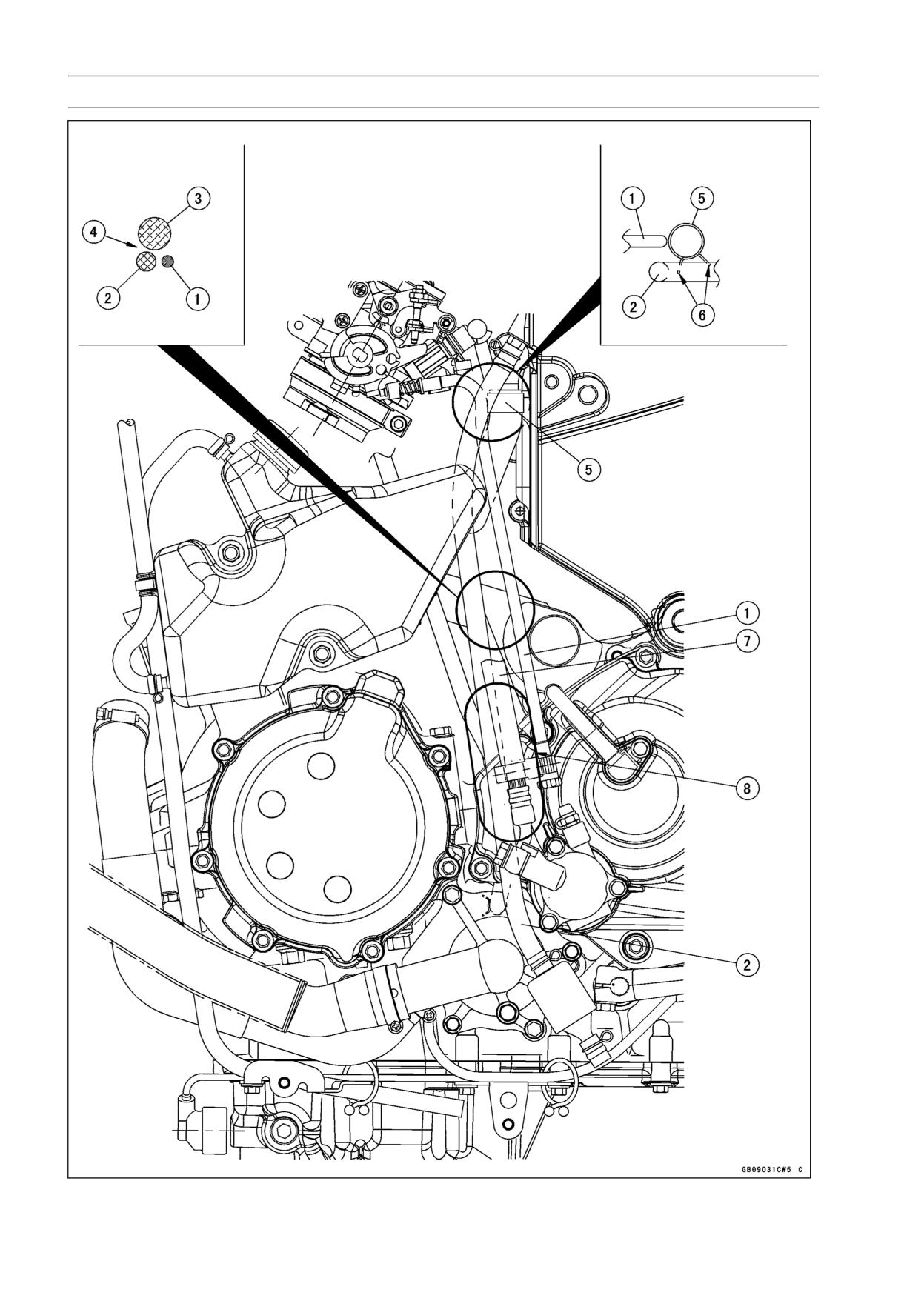
17-4 APPENDIX
Cable, Wire, and Hose Routing
APPENDIX 17-5
Cable, Wire, and Hose Routing
1. Idle Adjusting Screw
2. Through the air cleaner drain hose to the front of the clamp.
3. Main Harness
4. Through the air cleaner drain hose and idle adjusting screw to the outside of the main harness.
5. Clamp
6. Position the clamp so that its pinch heads do not touch the frame and air cleaner drain hose.
7. Clutch Hose
8. Through the air cleaner drain hose to the backside of the clutch hose.
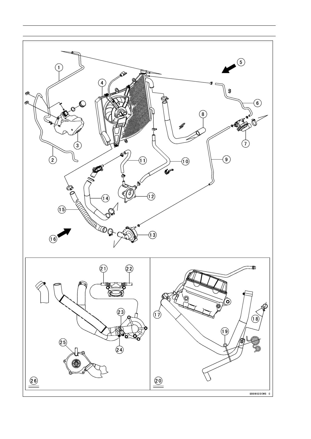
17-6 APPENDIX
Cable, Wire, and Hose Routing
APPENDIX 17-7
Cable, Wire, and Hose Routing
1. Reserver Tank Hosel
2. Reserver Tank Overflow Hose
3. Reserver Tank
4. Radiator
5. Right View
6. Air Bleeder Hose for Thermostat Housing
7. Thermostat Housing
8. Hose
9. Air Bleeder Hose for Water Pump
10. Outlet Hose
11. Inlet Hose
12. Oil Cooler
13. Water Pump
14. Hose
15. Hose
16. Left View
17. Align the white paint of the hose and mark of the thermostat housing cover.
18. About 45°
19. Clamp
20. Right View
21. Air Bleeder Hose for Water Pump
22. Air Bleeder Hose for Thermostat Housing
23. Align the white paint of the hose and mark of the water pump.
24. Install the hose so that white paint of the hose faces the front side.
25. Insert the air bleeder hose so that straight to the center of the impeller shaft.
26. Left View
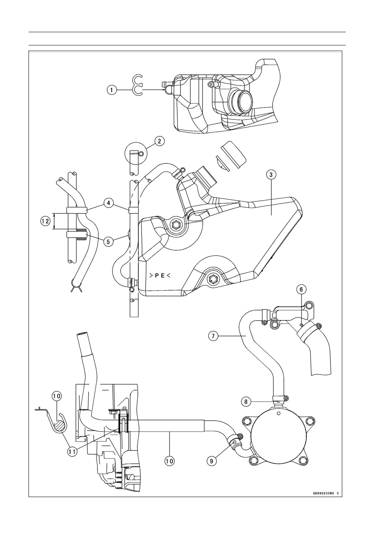
17-8 APPENDIX
Cable, Wire, and Hose Routing
APPENDIX 17-9
Cable, Wire, and Hose Routing
1. Clamp
2. Install the clamp so that knob of the clamp faces right side of the frame as shown in the figure.
3. Reserver Tank
4. Clamp
5. Clamp
6. Install the hose until projection.
7. Inlet Hose
8. Install the hose so that white paint of the hose faces the front side.
9. Install the hose so that white paint of the hose faces the front side.
10. Outlet Hose
11. Clamp
12. Approx. 20 mm (0.79 in.)
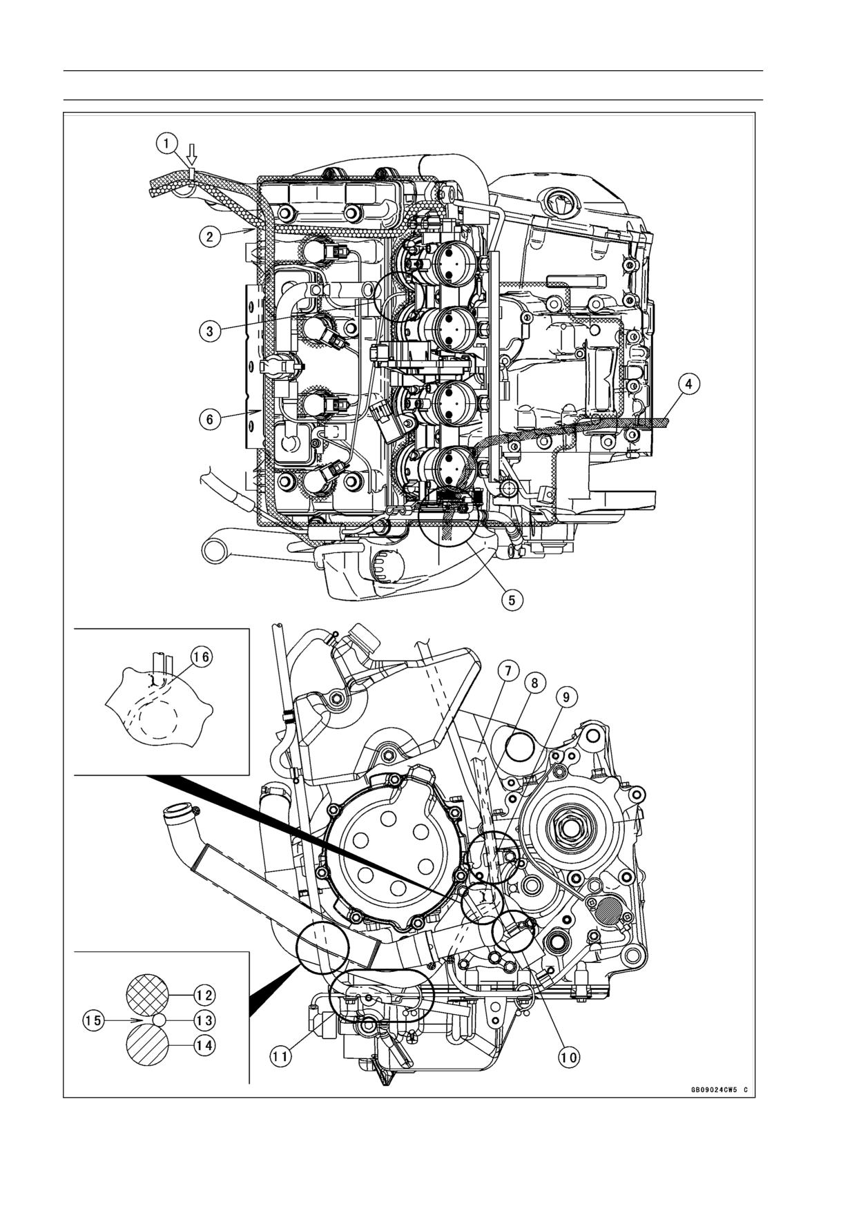
17-10 APPENDIX
Cable, Wire, and Hose Routing
APPENDIX 17-11
Cable, Wire, and Hose Routing
1. Clamp (Install the clamp from the arrow mark side.)
2. Through the reserver tank hose on the air bleeder hose for thermostat housing.
3. Through the subharness for sensor and valve between the #3 and #4 of the throttle body.
4. Alternator Lead (To the regulator/rectifier connector through the alternator subharness.)
5. Through the alternator lead backside of the air bleeder hose for water pump.
6. Through the reserver tank hose between the air switching valve and bracket.
7. Connect the gear position switch lead and sidestand switch lead to the main harness.
8. Air Cleaner Drain Hose
9. Through the air cleaner drain hose between the engine sprocket cover and clutch hose.
10. Through the air cleaner drain hose on the water pump, put in the space of the lower fairing.
11. Through the reserver tank overflow hose into the fairing bracket, and through the hose into the
clamp.
12. Hose
13. Reserver Tank Overflow Hose
14. Hose
15. Through the reserver tank overflow hose between the hose and hose.
16. Through the gear position switch lead backside of the air bleeder hose for water pump.
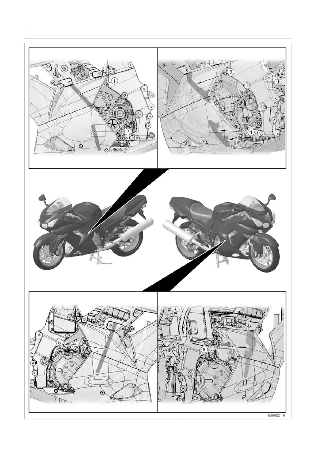
17-12 APPENDIX
Cable, Wire, and Hose Routing
APPENDIX 17-13
Cable, Wire, and Hose Routing
1. Pad
2. Pad
3. Fit the groove of the pad to the reserver tank, and fix the pad by the middle fairing.
4. Fit the grooves of the pad to the radiator hose and reserver tank drain hose, and fix the pad by
the lower fairing.
5. Pad
6. Fit the groove of the pad to the radiator hose, and fix the pad by the middle fairing.

17-14 APPENDIX
Cable, Wire, and Hose Routing
APPENDIX 17-15
Cable, Wire, and Hose Routing
1. Band (Clamp the main harness, and insert the band to the rear fender.)
2. Frame Ground Lead (Tighten the bolt with lead and bracket.)
3. Through the alternator subharness to the outside of the frame ground lead.
4. Alternator Connector (Install the alternator connector to the bracket.)
5. Connector (Insert the connector to the bracket.)
6. Alternator Subharness (Put the alternator subharness between the rear fender and frame.)
7. Alternator Lead
8. Through the alternator lead under the main harness.
9. Align the gray tape and the end of the battery case.
10. Fuel Hose
11. Main Harness
12. Alternator Lead (Through the alternator lead to the inside of the leads and hose.)
13. Sidestand Switch Lead Connector
14. Band (Clamp the main harness, and insert the band to the bracket.)
15. Throttle Body Subharness Connector (Install the connector to the bracket.)
16. Speed Sensor Lead Connector
17. Oil Pressure Switch/Gear Position Switch Lead Connector
18. Through the sidestand switch lead and oil pressure switch/gear position switch lead to the inside
of the chain cover from the hole of the notch.
19. Clamp (Clamp the fan motor lead.)
20. Through the engine harness to the outside of the clutch hose.
21. Engine Harness Connector (Install the engine harness connector to the bracket.)
22. Band (Clamp the main harness, and insert the band to the bracket.)
23. Stick Coil Lead Connector (Install the stick coil lead connector to the bracket of the cylinder
head cover.)
24. Through the stick coil lead under the throttle cables.
25. Band (Clamp the engine harness with the subframe.)
26. Clamp (Clamp the fan motor lead connector, and insert the clamp to the subframe.)
27. Through the oil pressure switch/gear position switch lead to the inside of the water pump.
28. Through the sidestand switch lead to the inside of the water pump.
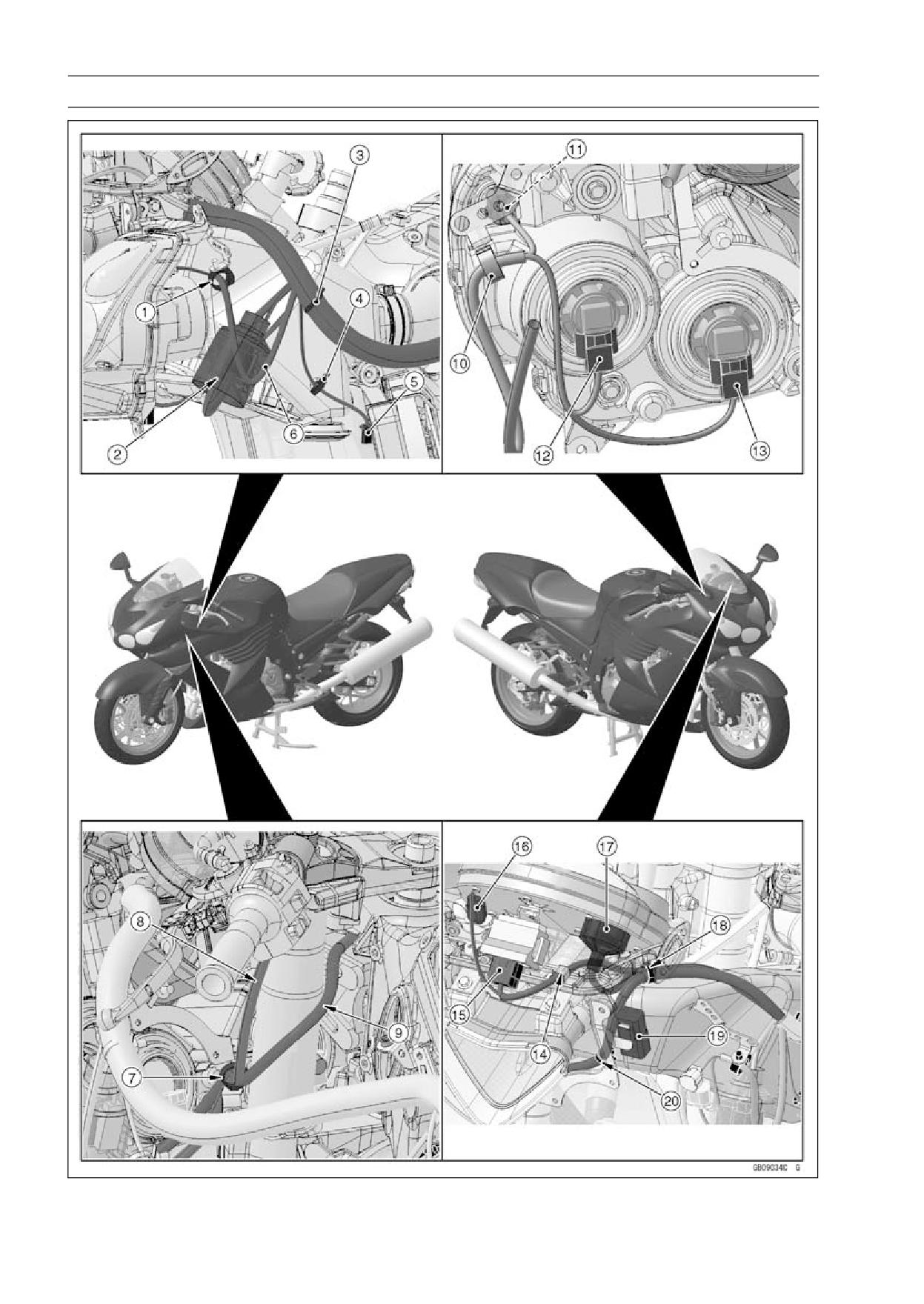
17-16 APPENDIX
Cable, Wire, and Hose Routing
APPENDIX 17-17
Cable, Wire, and Hose Routing
1. Through the headlight lead into the clamp (both sides).
2. After ignition switch lead connector and left switch housing lead connector connecting, put the
connectors in the water-proof cover.
3. Clamp (Clamp the main harness, and insert the clamp to the middle air inlet duct.)
4. Clamp (Clamp the left turn signal lead, and insert the clamp to the middle air inlet duct.)
5. Left Turn Signal Light Lead Connector
6. Headlight Lead
7. Through the left switch housing lead and ignition switch lead into the clamp, and insert the clamp
to the bracket.
8. Through the left switch housing lead to the outside of the front fork, and through the lead into
the clamp.
9. Through the ignition switch lead to the backside of the front fork from the inside of the front fork,
and through the lead into the clamp.
10. Clamp
11. Left City Light
12. Headlight (High)
13. Headlight (Low)
14. Install the clamp outside as shown in the figure, and clamp the immobilizer amplifier lead.
15. Immobilizer Amplifier Lead Connector
16. Vehicle-down Sensor Lead Connector
17. Meter Unit Lead Connector
18. Through the main harness and immobilizer amplifier lead into the clamp.
19. Headlight Relay (High)
20. Clamp (Clamp the main harness, and insert the clamp to the middle air inlet duct.)
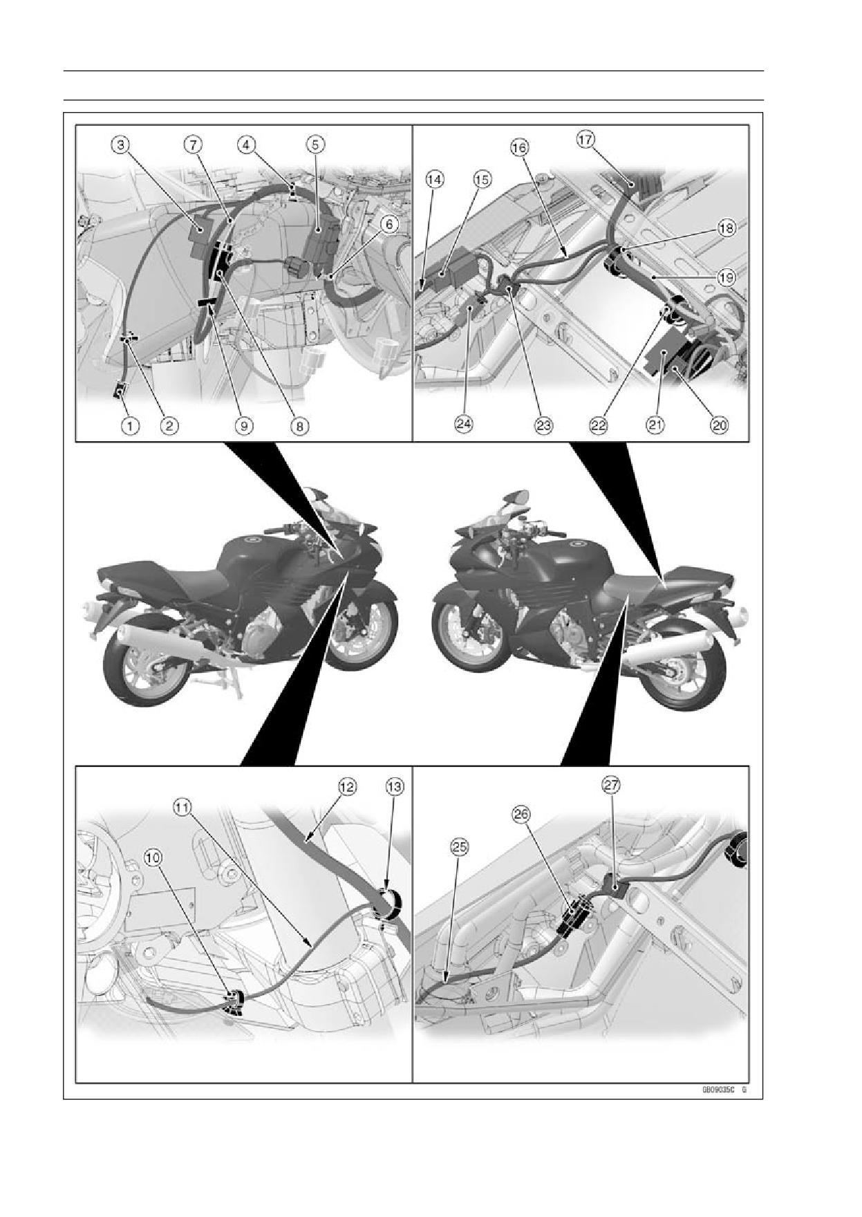
17-18 APPENDIX
Cable, Wire, and Hose Routing
APPENDIX 17-19
Cable, Wire, and Hose Routing
1. Right Turn Signal Light Lead Connector
2. Clamp (Clamp the right turn signal lead, and insert the clamp to the middle air inlet duct.)
3. *Front Wheel Rotation Sensor Lead Connector
4. Clamp (Clamp the main harness, and insert the clamp to the middle air inlet duct.)
5. Headlight Relay (Low)
6. Clamp (Clamp the main harness, and insert the clamp to the middle air inlet duct.)
7. Right Switch Housing Lead and Horn Lead
8. Right Switch Housing Lead Connector
9. Through the right switch housing lead, horn lead, headlight lead and *front wheel rotation sensor
lead into the clamp.
10. Clamp (Clamp the horn lead, and insert the clamp to the cover.)
11. Through the horn lead to the outside of the front fork.
12. Through the right switch housing lead to the outside of the front fork.
13. Through the right switch housing lead and horn lead into the clamp.
14. Through the rear wheel rotation sensor lead to the inside of the rear brake reservoir tank.
15. *Front Wheel Rotation Sensor Lead Connector (Install the front wheel rotation sensor lead con-
nector to the bracket.)
16. Through the main harness lead on the rear brake reservoir tank hose.
17. Fuse Box 1
18. Clamp
19. Alternator Subharness
20. Fuel Pump Lead Connector
21. Fuel Level Sensor Lead Connector
22. Clamp
23. Clamp (Clamp the rear brake light switch lead and *rear wheel rotation sensor lead.)
24. Rear Brake Light Switch Lead Connector
25. Through the rear brake light switch lead to the outside of the separator.
26. Rear Brake Light Switch Lead Connector
27. Clamp (Clamp the rear brake light switch lead.)
* ZX1400B Models only
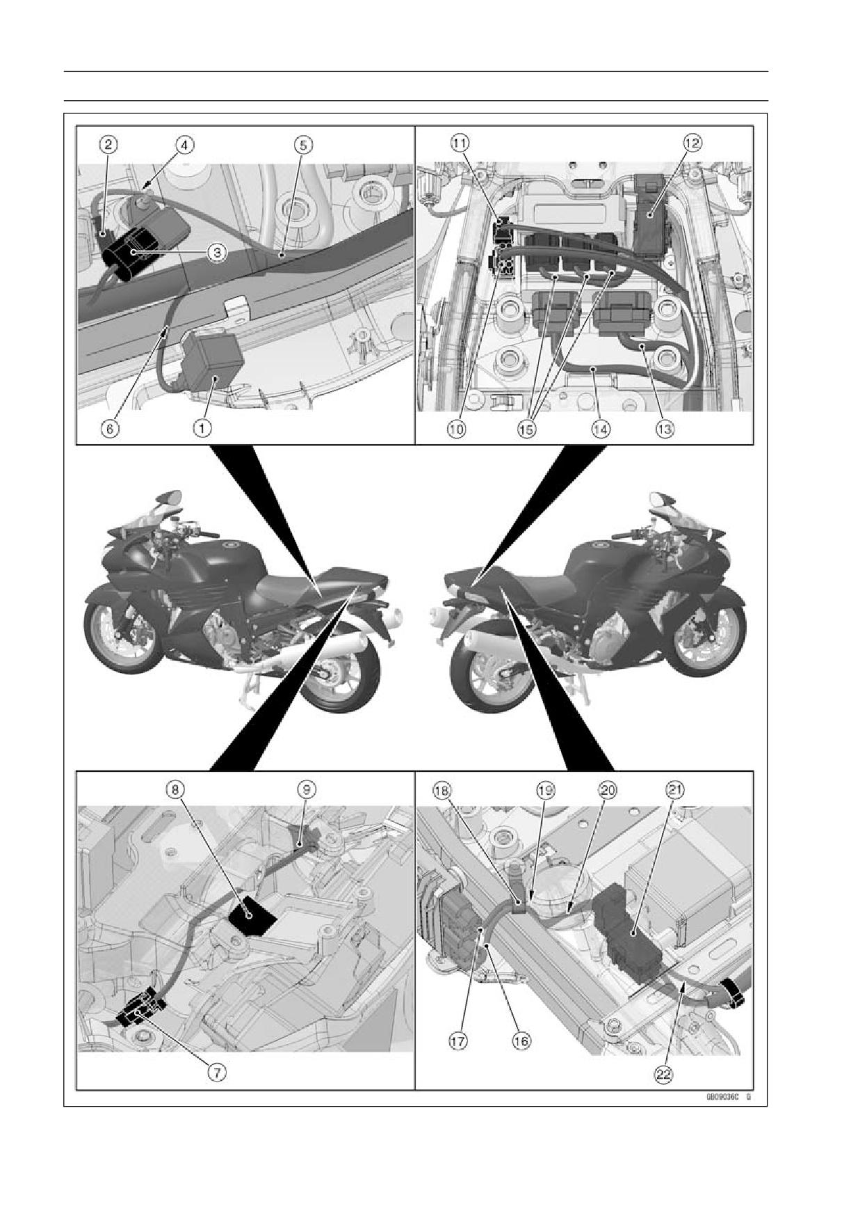
17-20 APPENDIX
Cable, Wire, and Hose Routing
APPENDIX 17-21
Cable, Wire, and Hose Routing
1. Turn Signal Relay
2. License Plate Light Lead Connector
3. Atomospheric Pressure Sensor Lead Connector
4. Through the license plate light lead to the inside of the atomospheric pressure sensor.
5. License Plate Light Lead
6. Through the turn signal relay lead between the rear frame and rear frame pipe.
7. Rear Left Turn Signal Light Lead Connector
8. Tail/Brake Light Lead Connector
9. Rear Right Turn Signal Light Lead Connector
10. *ABS Kawasaki Self-diagnosis System Connector (Fix the ABS Kawasaki self-diagnosis system
connector with the sponge.)
11. Immobilizer/Kawasaki Diagnostic System Connector (Fix the Immobilizer/Kawasaki diagnositic
system connector with the sponge.)
12. Fuse Box 2
13. ECU Lead
14. ECU Lead
15. Relay Box Leads
16. Alternator Subharness
17. Alternator Lead
18. Clamp (Clamp the alternator lead and alternator subharness.)
19. Through the alternator lead and alternator subharness to the outside of the rear frame.
20. Through the alternator lead and alternator subharness under the rear brake reservoir tank.
21. Fuse Box 1
22. Through the alternator subharness under the bracket.
* ZX1400B Models only
17-22 APPENDIX
Cable, Wire, and Hose Routing
APPENDIX 17-23
Cable, Wire, and Hose Routing
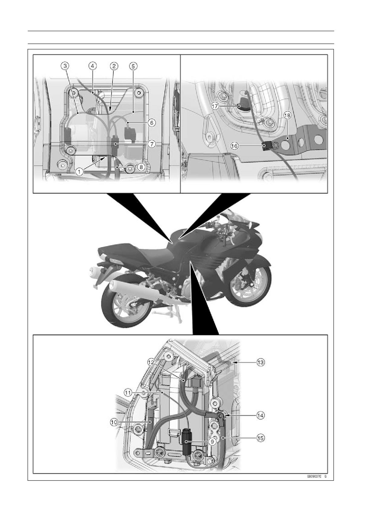
1. Through the main harness to the hole of the lower side.
2. Through the inlet air temperature sensor lead to the hole of the upper side.
3. *ABS Hydraulic Unit Lead
4. Inlet Air Temperature Sensor Lead
5. Battery Negative Lead
6. Starter Relay Lead
7. Battery Positive Lead Connector (Install the battery positive lead connector to the battery case.)
8. Starter Motor Cable
9. Battery Negative Lead Connector (Install the battery negative lead connector to the bracket.)
10. Battery Positive Cable
11. Battery Negative Lead
12. Battery Negative Cable
13. Direction of Battery Negative Terminal Installation
14. Tighten the bolt with battery negative cable and battery negative lead.
15. Battery Negative Cable
16. Clamp (Clamp the inlet air temperature sensor lead.)
17. Inlet Air Temperature Sensor
18. *Bracket
* ZX1400B Models only
17-24 APPENDIX
Cable, Wire, and Hose Routing
APPENDIX 17-25
Cable, Wire, and Hose Routing
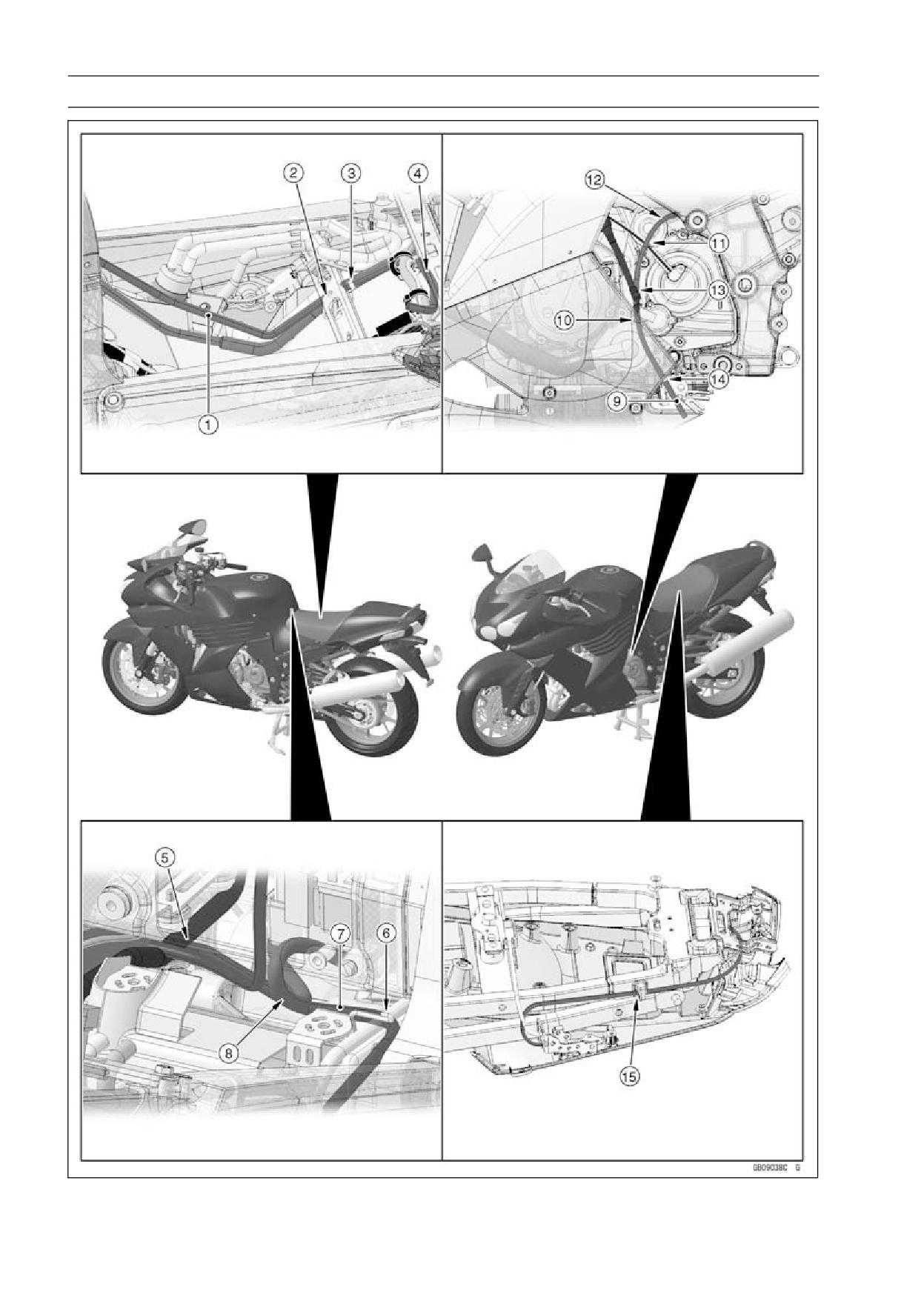
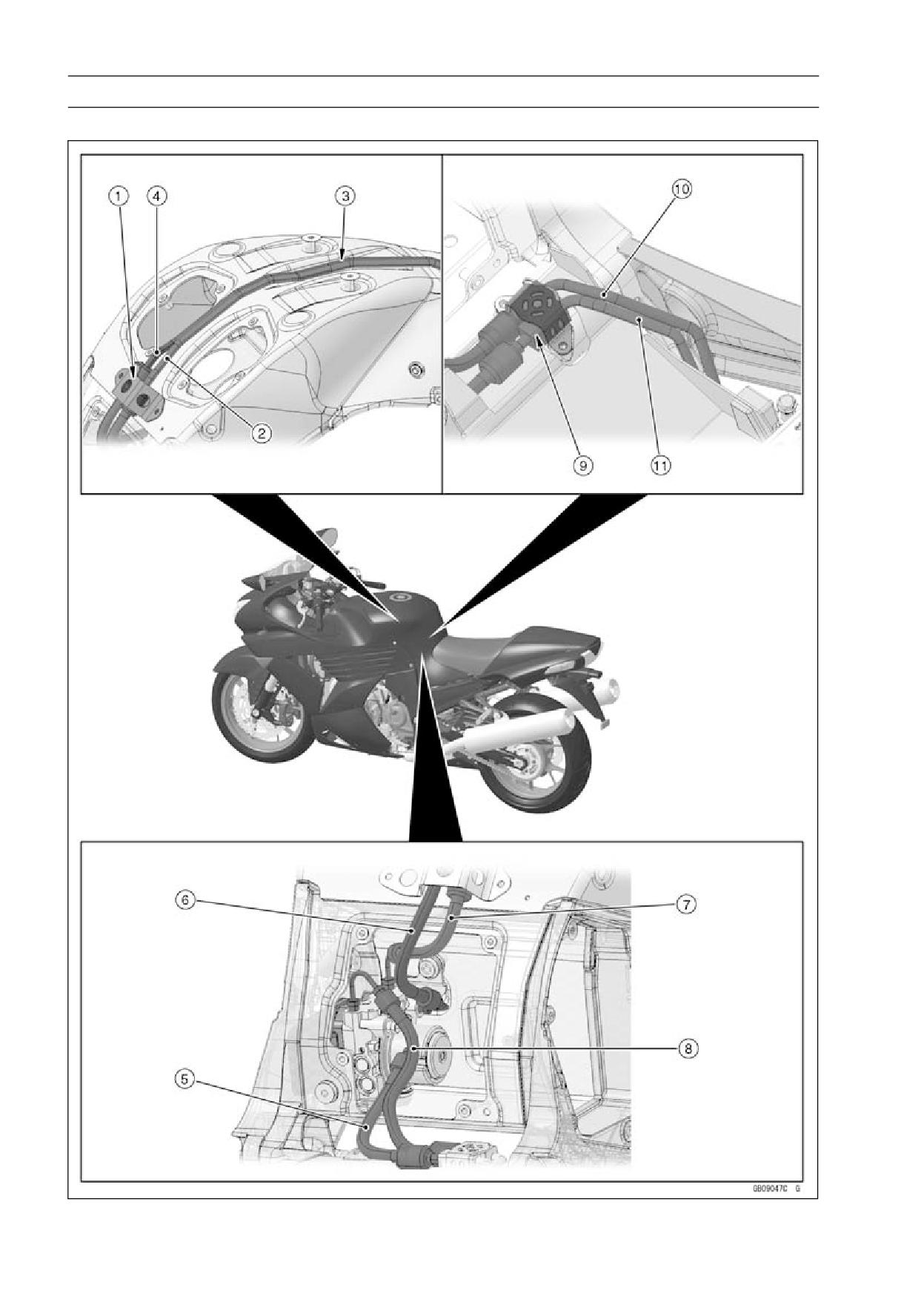
1. Fuel Tank Drain Hose
2. Through the fuel tank drain hose under the bracket.
3. Position a yellow tape at the rear end of bracket.
4. Through the fuel tank drain hose to the backside of the clamp.
5. Through the fuel tank drain hose under the fuel hose.
6. Through the fuel tank drain hose under the clamp.
7. Fuel Tank Drain Hose
8. Through the fuel tank drain hose under the starter motor cable.
9. Fuel Tank Drain Hose
10. Through the fuel tank drain hose under the lower fairing.
11. Through the fuel tank drain hose on the speed sensor lead.
12. Through the fuel tank drain hose under the heat insulation rubber plate.
13. Through the fuel tank drain hose under the clutch hose.
14. Position a yellow tape at the end of lower fairing.
15. Through the seat lock cable to the rear frame.
17-26 APPENDIX
Cable, Wire, and Hose Routing
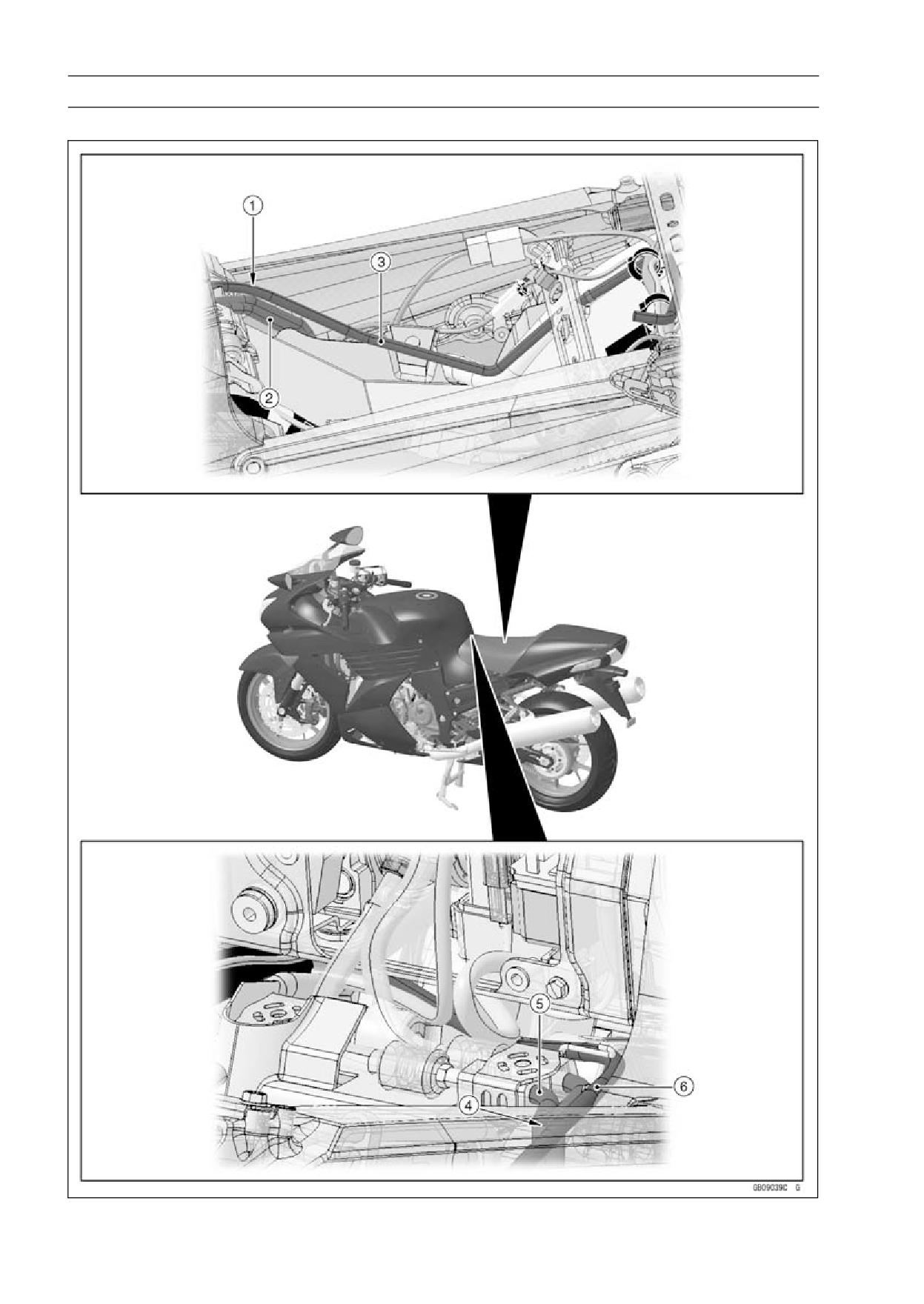
ZX1400B Models
APPENDIX 17-27
Cable, Wire, and Hose Routing
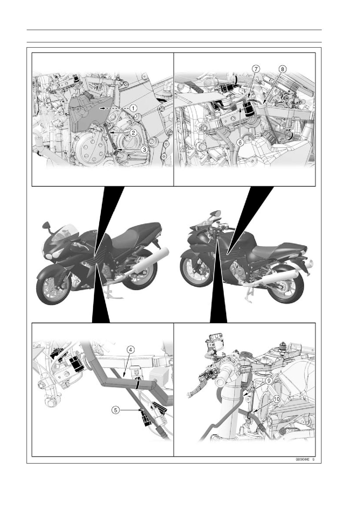
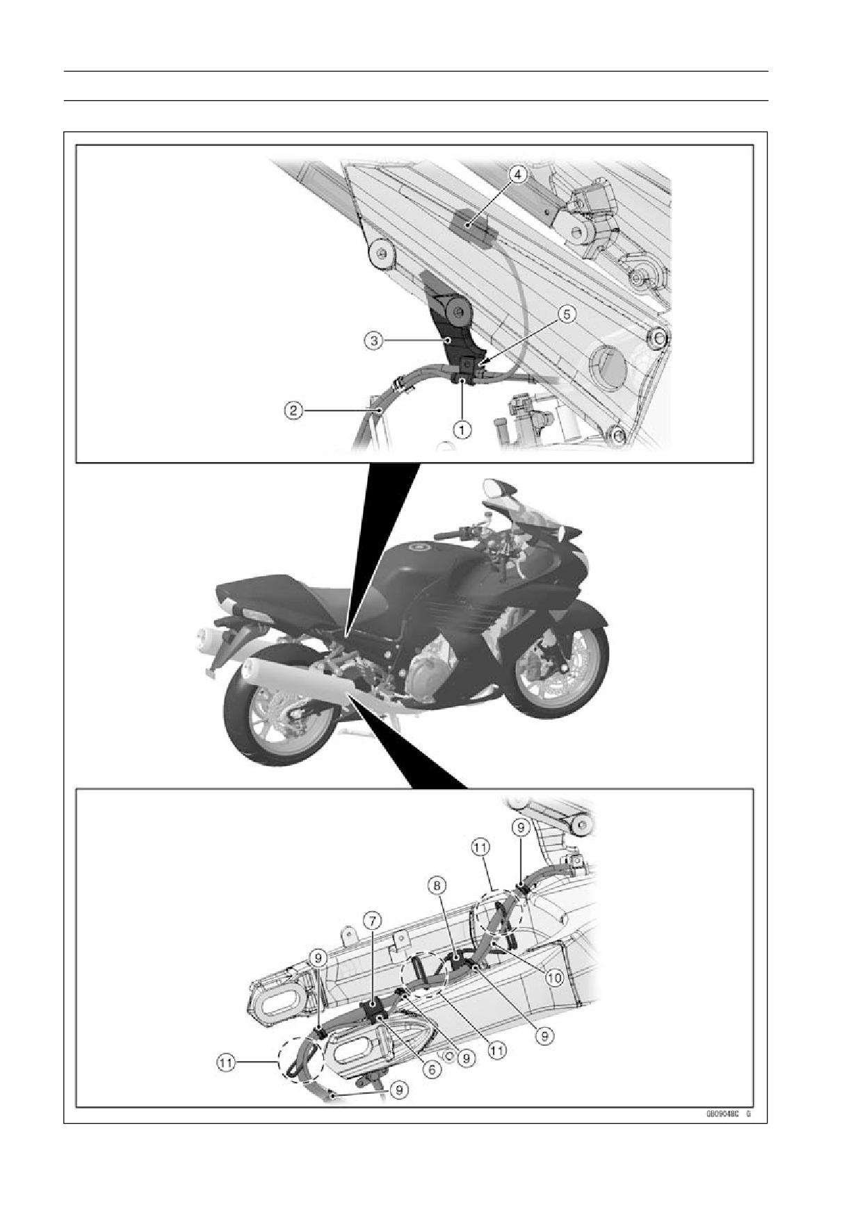
1. Through the fuel tank drain hose on the brake pipe.
2. Brake Pipe
3. Fuel Tank Drain Hose
4. Through the fuel tank drain hose on the brake pipe.
5. Brake Pipe
6. Fuel Tank Drain Hose
17-28 APPENDIX
Cable, Wire, and Hose Routing
APPENDIX 17-29
Cable, Wire, and Hose Routing
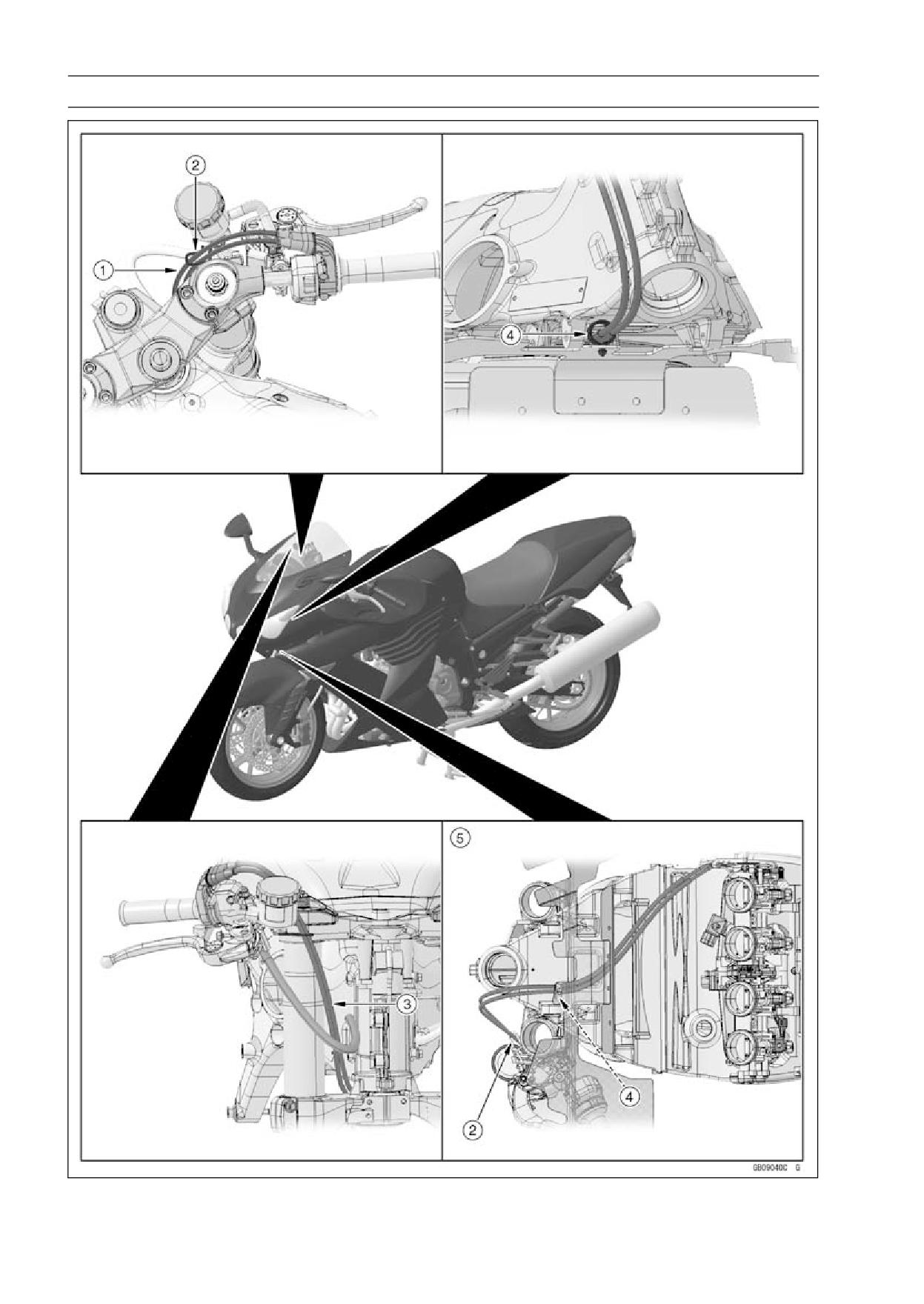
1. Through the throttle cables inside of the brake hose.
2. Through the throttle cables to the clamp of the reservoir bracket.
3. Through the throttle cables inside of the brake hose.
4. Through the throttle cables to the clamp.
5. Viewed Bottom
17-30 APPENDIX
Cable, Wire, and Hose Routing
APPENDIX 17-31
Cable, Wire, and Hose Routing
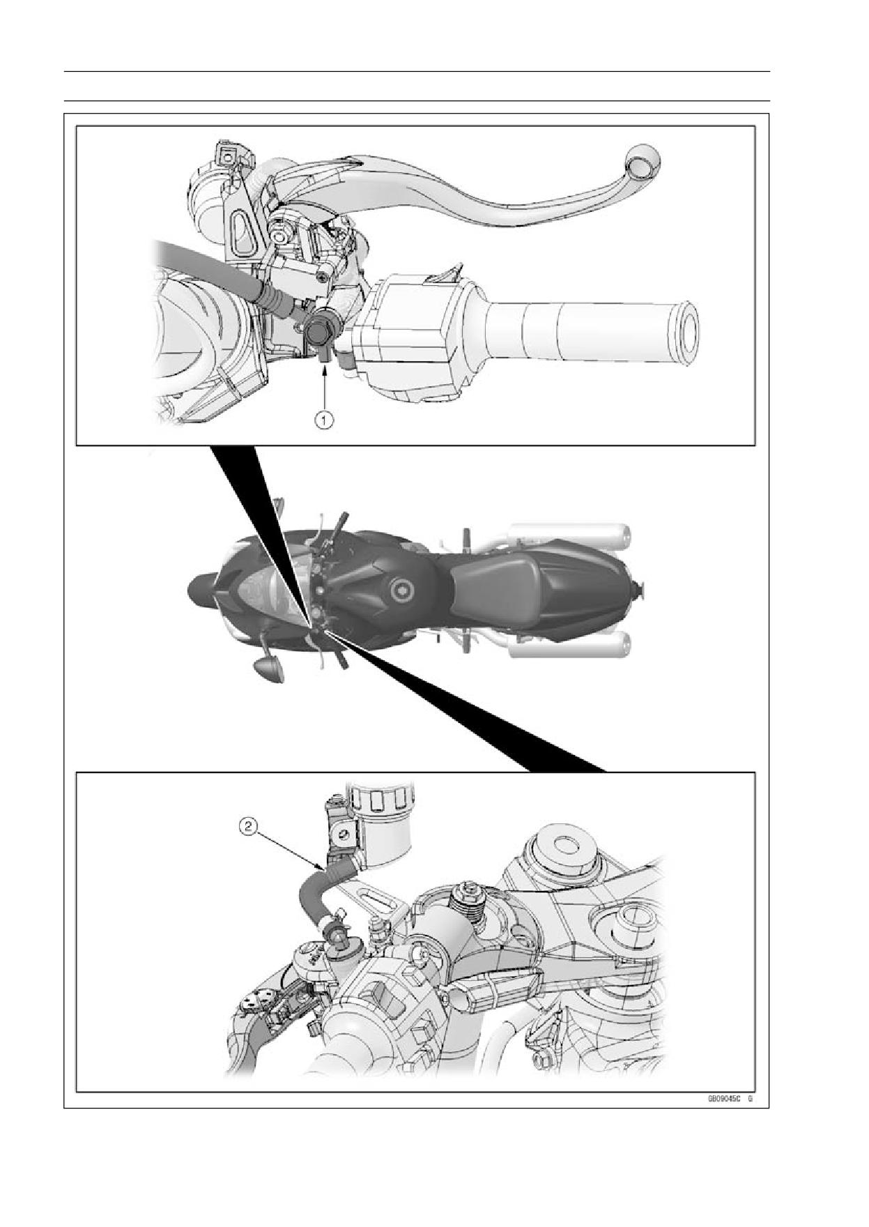
1. Through the clutch hose inside the coolant reserver tank.
2. Through the clutch hose outside the sidestand switch, speed sensor, oil pressure switch/gear
position switch leads.
3. Install the cluth hose joint as shown in the figure (face the clutch hose joint pipe inside).
4. Through the clutch hose inside the main harness.
5. Through the clutch hose outside the sidestand switch, speed sensor and oil pressure switch/gear
position switch lead connectors.
6. Clamp the clutch hose to the clamp of the subframe.
7. Through the clutch hose inside the radiator fan lead.
8. Through the clutch hose inside the subframe.
9. Through the ignition switch lead upper the clutch hose.
10. Through the clutch hose in the clamp.
17-32 APPENDIX
Cable, Wire, and Hose Routing
APPENDIX 17-33
Cable, Wire, and Hose Routing
1. Install the clutch hose joint as shown in the figure (face the projection of the clutch hose joint
backward).
2. Through the clutch fluid reservoir hose inside the bracket.
17-34 APPENDIX
Cable, Wire, and Hose Routing
APPENDIX 17-35
Cable, Wire, and Hose Routing
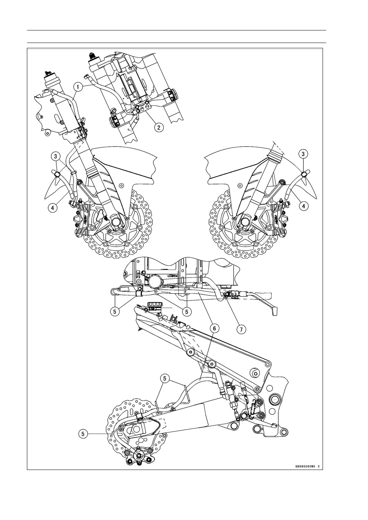
1. Brake Hose
2. Bracket
3. Clamps (Insert the clamps in the front fender.)
4. Brake Hose
5. Clamps
6. Brake Hose
7. Face the white paint mark upward.
17-36 APPENDIX
Cable, Wire, and Hose Routing
ZX1400B Models
APPENDIX 17-37
Cable, Wire, and Hose Routing
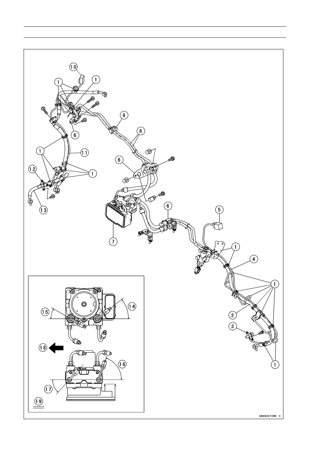
1. Clamps
2. Brake Hose
3. Rear Wheel Rotation Sensor
4. Rear Wheel Rotation Sensor Lead
5. Rear Wheel Rotation Sensor Lead Connector
6. Bracket
7. ABS Hydraulic Unit
8. Brake Pipes
9. Damper
10. Front Wheel Rotation Sensor Lead Connector
11. Front Wheel Rotation Sensor Lead
12. Front Wheel Rotation Sensor
13. Brake Hose
14. Approx. 38.5°
15. Approx. 30°
16. Approx. 71°
17. Approx. 48°
18. Front
19. Install the brake hose joint pipes as shown in the figure.
17-38 APPENDIX
Cable, Wire, and Hose Routing
ZX1400B Models
APPENDIX 17-39
Cable, Wire, and Hose Routing
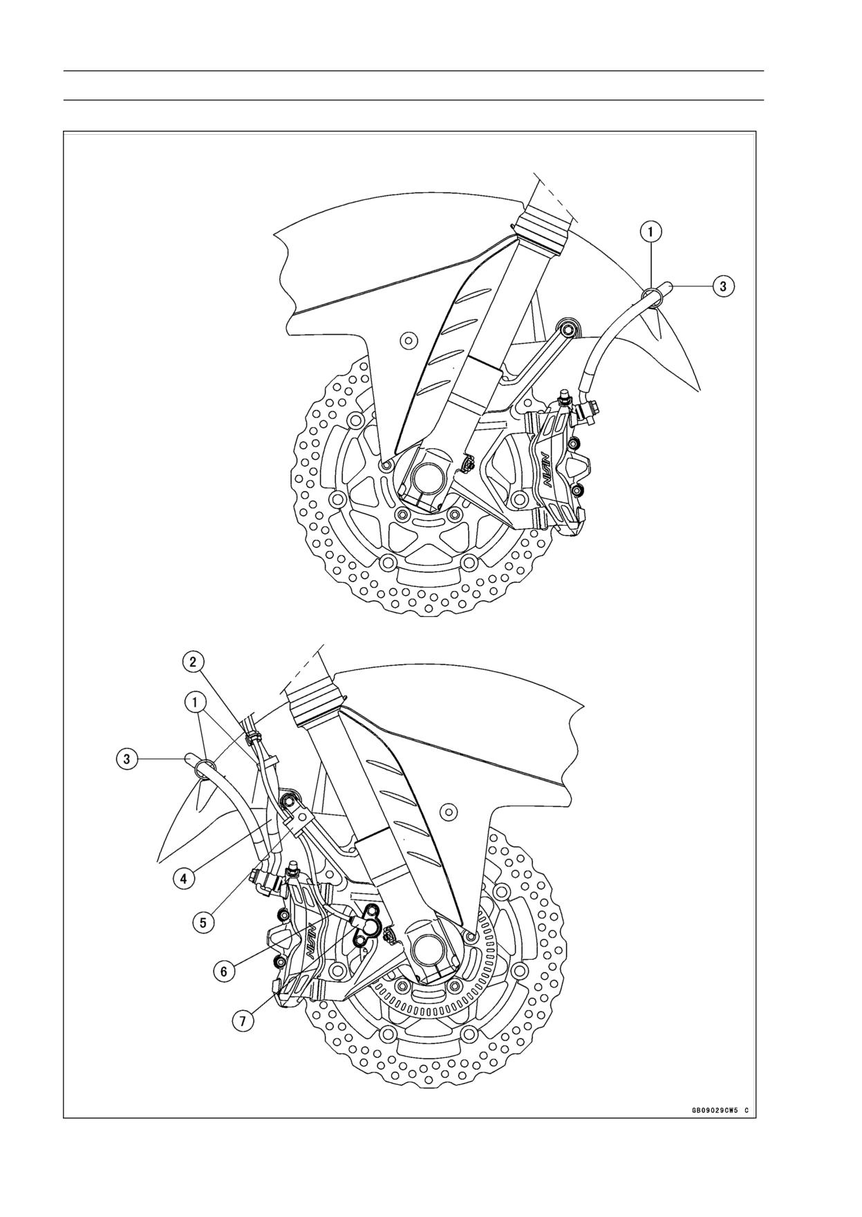
1. Clamps (Insert the clamps in the front fender.)
2. Clamp (Clamp the brake hose, and align the clamp with white tape of the front wheel rotation
sensor lead.)
3. Brake Hose
4. Brake Hose (Front Master Cylinder ∼ Right Front Caliper)
5. Clamp (Clamp the front wheel rotation sensor.)
6. Front Wheel Rotation Sensor Lead
7. Front Wheel Rotation Sensor
17-40 APPENDIX
Cable, Wire, and Hose Routing
ZX1400B Models
APPENDIX 17-41
Cable, Wire, and Hose Routing
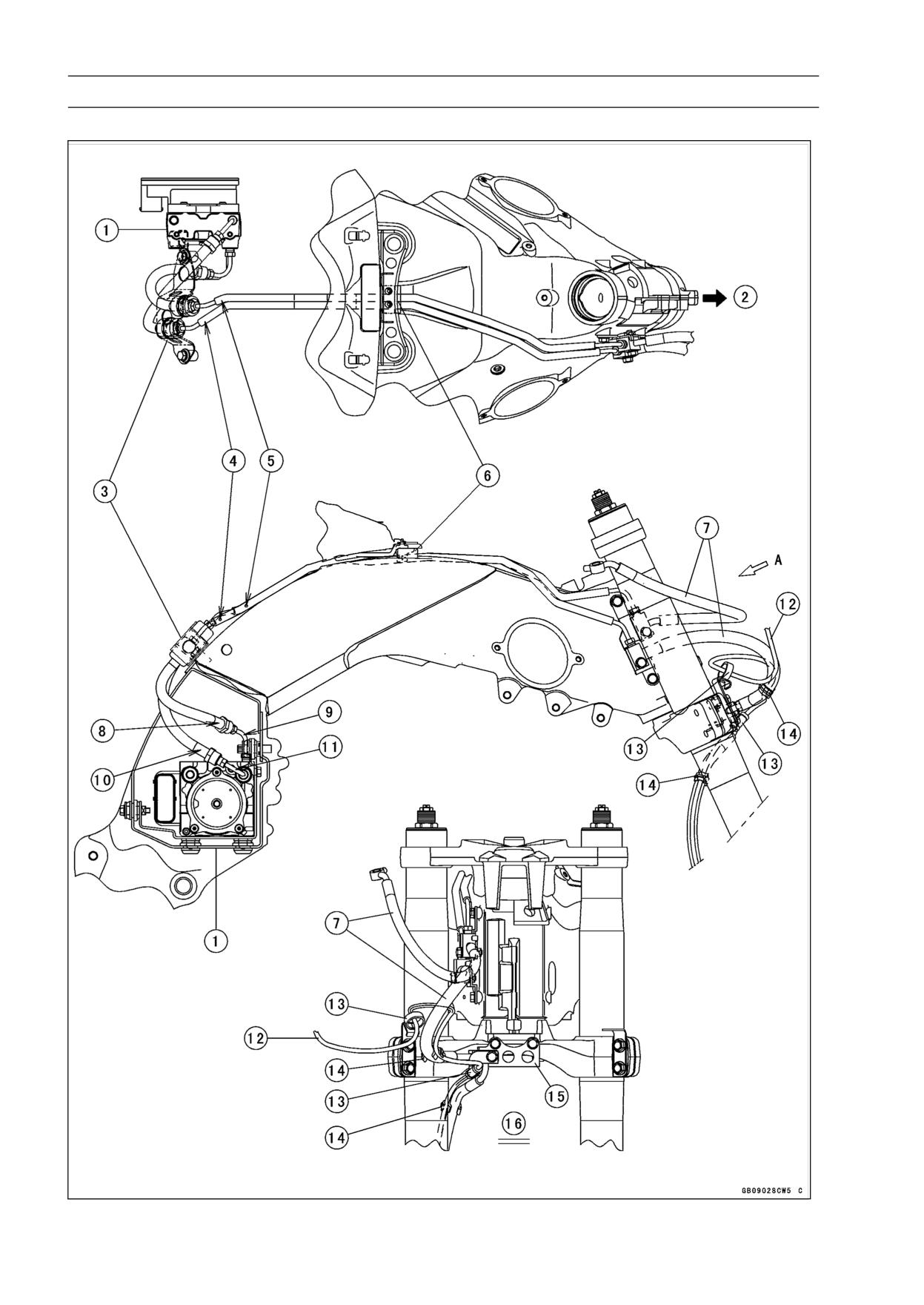
1. ABS Hydraulic Unit
2. Front
3. Bracket
4. Brake Pipe (One Blue Paint Mark)
5. Brake Pipe (One White Paint Mark)
6. Damper
7. Brake Hose
8. Brake Hose (One Blue Paint Mark)
9. Brake Hose Joint Pipe (One Blue Paint Mark)
10. Brake Hose (One White Paint Mark)
11. Brake Hose Joint Pipe (One White Paint Mark)
12. Front Wheel Rotation Sensor Lead
13. Clamps (Clamp the front wheel rotation sensor.)
14. Clamps (Clamp the brake hose, and align the clamps with white tapes of the front wheel rotation
sensor lead.)
15. Bracket
16. Viewed A
17-42 APPENDIX
Cable, Wire, and Hose Routing
ZX1400B Models
APPENDIX 17-43
Cable, Wire, and Hose Routing
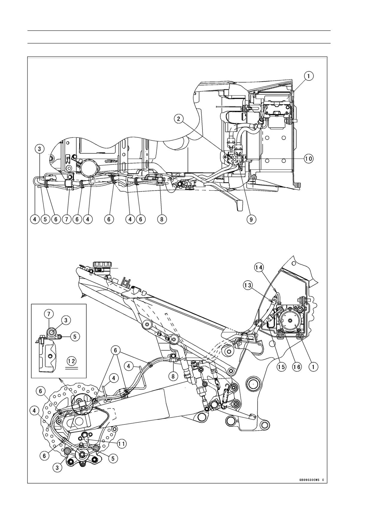
1. ABS Hydraulic Unit
2. Brake Pipe (Two White Paint Marks)
3. Brake Hose
4. Clamps (Through only the brake hose in the clamps.)
5. Rear Wheel Rotation Sensor Lead
6. Clamps (Clamp the brake hose, and align the clamps with white tape of the rear wheel rotation
sensor lead.)
7. Clamp (Clamp the brake hose and rear wheel rotation sensor.)
8. Clamp (Clamp the brake hose and rear wheel rotation sensor.)
9. Brake Pipe (Two Blue Paint Marks)
10. Bracket
11. Rear Wheel Rotation Sensor
12. Viewed Rear Side
13. Brake Hose (Two Blue Paint Marks)
14. Brake Hose Joint Pipe (Two Blue Paint Marks)
15. Brake Hose (Two White Paint Marks)
16. Brake Hose Joint Pipe (One White Paint Mark)
17-44 APPENDIX
Cable, Wire, and Hose Routing
ZX1400B Models
APPENDIX 17-45
Cable, Wire, and Hose Routing
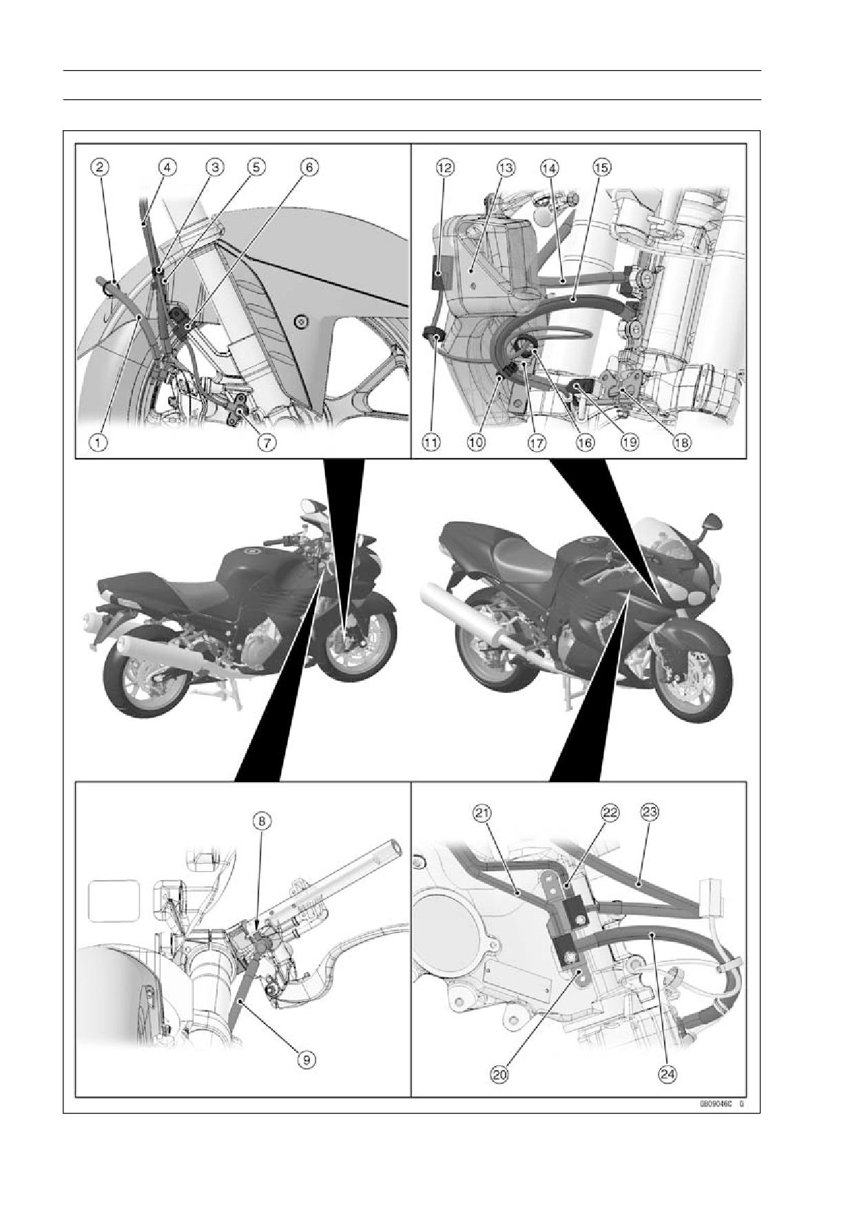
1. Brake Hose
2. Clamps (Through the brake hose in the clamp on both sides.)
3. Clamps (Clamp the brake hose, and align the clamps with white tapes of the front wheel rotation
sensor lead.)
4. Brake Hose
5. Clamp (Through only the brake hose in the clamp.)
6. Clamp
7. Front Wheel Rotation Sensor
8. Install the brake hose joint as shown in the figure (face the projection of the brake hose joint
backward.)
9. Brake Hose
10. Clamp (Clamp the brake hose, and align the clamp with white tape of the front wheel rotation
sensor lead.)
11. Clamp
12. Front Wheel Rotation Sensor Lead Connector
13. Right Middle Air Inlet Duct
14. Brake Hose
15. Brake Hose
16. Clamp
17. Braket
18. Braket
19. Clamp
20. Bracket
21. Brake Pipe
22. Brake Pipe
23. Brake Hose
24. Brake Hose
17-46 APPENDIX
Cable, Wire, and Hose Routing
ZX1400B Models
APPENDIX 17-47
Cable, Wire, and Hose Routing
1. Bracket (Push the joint portions of the brake pipe, and clamp them.)
2. Brake Pipe (One Blue Paint Mark, ABS Hydraulic Unit Side)
3. Align the brake pipes with groove of the frame.
4. Brake Pipe (One White Paint Mark, ABS Hydraulic Unit Side)
5. Brake Hose (Two White Paint Marks) and Brake Hose Joint Pipe (One White Paint)
6. Brake Hose (One White Paint Mark) and Brake Hose Joint Pipe (One White Paint)
7. Brake Hose (One Blue Paint Mark) and Brake Hose Joint Pipe (One Blue Paint Mark)
8. Brake Hose (Two Blue Paint Marks) and Brake Hose Joint Pipe (Two Blue Paint Mraks)
9. Insert the brake pipes to the holes of damper, and fit the projection of damper into the hole of
bracket.
10. Brake Pipe (Two Blue Paint Marks)
11. Brake Pipe (Two White Paint Marks)
17-48 APPENDIX
Cable, Wire, and Hose Routing
ZX1400B Models
APPENDIX 17-49
Cable, Wire, and Hose Routing
1. Clamp
2. Brake Hose
3. Bracket (Install the bracket from back of the rear frame.)
4. Rear Wheel Rotation Sensor Lead Connector
5. Clamp the joint portion of the brake hose into the bracket.
6. Clamp
7. Clamp
8. Clamp
9. Clamps (Clamp the brake hose, and align the clamps with white tape of the rear wheel rotation
sensor lead.)
10. Rear Wheel Rotation Sensor Lead
11. Clamps (Through only the brake hose in the clamps.)
17-50 APPENDIX
Cable, Wire, and Hose Routing
California Model
APPENDIX 17-51
Cable, Wire, and Hose Routing
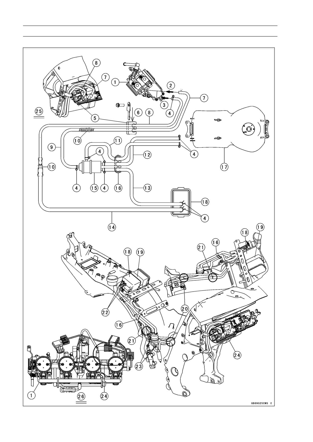
1. Throttle Body Assy
2. To the fitting of the throttle body #3.
3. To the fitting of the throttle body #4.
4. Clamps
5. Clamp
6. Insert the bracket to the holes of clamp.
7. Hose (White)
8. Hose (Green)
9. Hose (White)
10. Fittings
11. Hose (Red)
12. Hose (Blue)
13. Hose (Blue)
14. Hose (Green)
15. Separator
16. Clamp
17. Fuel Tank
18. Canister
19. Band
20. Connected position of the white hoses and fitting.
21. Connected position of the green hoses and fitting.
22. Face the paint marks upward.
23. Face the paint marks to the right side.
24. Through the hoses inside the throttle body subharness.
25. Viewed Right Side
26. Viewed Upside
17-52 APPENDIX
Troubleshooting Guide
NOTE
Stick coil shorted or not in good contact
○Refer to the Fuel System chapter for most
Stick coil trouble
of DFI trouble shooting guide.
ECU trouble
○This is not an exhaustive list, giving every
Camshaft position sensor trouble
possible cause for each problem listed. It
Gear position, starter lockout, or side stand
is meant simply as a rough guide to assist
switch trouble
the troubleshooting for some of the more
Crankshaft sensor trouble
common difficulties.
Ignition switch or engine stop switch
shorted
Engine Doesn’t Start, Starting
Starter system wiring shorted or open
Difficulty:
Main 30A or ignition fuse blown
Starter motor not rotating:
Fuel/air mixture incorrect:
Ignition and engine stop switch not ON
Bypass screw and/or idle adjusting screw
Starter lockout switch or gear position
maladjusted
switch trouble
Air passage clogged
Starter motor trouble
Air cleaner clogged, poorly sealed, or miss-
Battery voltage low
ing
Starter relay not contacting or operating
Leak from oil filler cap, crankcase breather
Starter button not contacting
hose or air cleaner drain hose.
Starter system wiring open or shorted
Compression Low:
Ignition switch trouble
Spark plug loose
Engine stop switch trouble
Cylinder head not sufficiently tightened
Main 30A or ignition fuse blown
down
Starter motor rotating but engine doesn’t
Cylinder, piston worn
turn over:
Piston ring bad (worn, weak, broken, or
Vehicle-down sensor (DFI) coming off
sticking)
Immobilizer system trouble
Piston ring/groove clearance excessive
Starter clutch trouble
Cylinder head gasket damaged
Starter idle gear trouble
Cylinder head warped
Engine won’t turn over:
Valve spring broken or weak
Valve seizure
No valve clearance
Valve lifter seizure
Valve not seating properly (valve bent,
Cylinder, piston seizure
worn, or carbon accumulation on the
Crankshaft seizure
seating surface)
Connecting rod small end seizure
Connecting rod big end seizure
Poor Running at Low Speed:
Transmission gear or bearing seizure
Spark weak:
Camshaft seizure
Battery voltage low
Starter idle gear seizure
Immobilizer system trouble
Balancer bearing seizure
Stick coil trouble
No fuel flow:
Stick coil shorted or not in good contact
No fuel in tank
Spark plug dirty, broken, or maladjusted
Fuel pump trouble
Spark plug incorrect
Fuel tank air vent obstructed
ECU trouble
Fuel filter clogged
Camshaft position sensor trouble
Fuel line clogged
Crankshaft sensor trouble
No spark; spark weak:
Fuel/air mixture incorrect:
Vehicle-down sensor (DFI) coming off
Bypass screw maladjusted
Ignition switch not ON
Air passage clogged
Engine stop switch turned OFF
Air bleed pipe bleed holes clogged
Clutch lever not pulled in or gear not in neu-
Pilot passage clogged
tral
Air cleaner clogged, poorly sealed, or miss-
Battery voltage low
ing
Immobilizer system trouble
Fuel tank air vent obstructed
Spark plug dirty, broken, or gap malad-
Fuel pump trouble
justed
Throttle body assy holder loose
Spark plug incorrect
Air duct holder loose
APPENDIX 17-53
Troubleshooting Guide
Compression low:
Cylinder head not sufficiently tightened
Spark plug loose
down
Cylinder head not sufficiently tightened
No valve clearance
down
Cylinder, piston worn
No valve clearance
Piston ring bad (worn, weak, broken, or
Cylinder, piston worn
sticking)
Piston ring bad (worn, weak, broken, or
Piston ring/groove clearance excessive
sticking)
Cylinder head gasket damaged
Piston ring/groove clearance excessive
Cylinder head warped
Cylinder head gasket damaged
Valve spring broken or weak
Cylinder head warped
Valve not seating properly (valve bent,
Valve spring broken or weak
worn, or carbon accumulation on the
Valve not seating properly (valve bent,
seating surface.)
worn, or carbon accumulation on the
Knocking:
seating surface)
Carbon built up in combustion chamber
Camshaft cam worm
Fuel poor quality or incorrect
Run-on (dieseling):
Spark plug incorrect
Ignition switch trouble
ECU trouble
Engine stop switch trouble
Miscellaneous:
Fuel injector trouble
Throttle valve won’t fully open
Loosen terminal of battery (-) cable or ECU
Brake dragging
ground lead
Clutch slipping
Carbon accumulating on valve seating sur-
Engine overheating
face
Engine oil level too high
Engine overheating
Engine oil viscosity too high
Other:
Drive train trouble
ECU trouble
Camshaft cam worm
Throttle body assy not synchronizing
Air suction valve trouble
Engine oil viscosity too high
Air switching valve trouble
Drive train trouble
Catalytic converter melt down due to muffler
Brake dragging
overheating (KLEEN)
Clutch slipping
Engine overheating
Overheating:
Air suction valve trouble
Firing incorrect:
Air switching valve trouble
Spark plug dirty, broken, or maladjusted
Spark plug incorrect
Poor Running or No Power at High
ECU trouble
Speed:
Muffler overheating:
Firing incorrect:
For KLEEN, do not run the engine even if
Spark plug dirty, broken, or maladjusted
with only one cylinder misfiring or poor
Spark plug incorrect
running (Request the nearest service fa-
Stick coil shorted or not in good contact
cility to correct it)
trouble
For KLEEN, do not push-start with a dead
Stick coil trouble
battery (Connect another full-charged
ECU trouble
battery with jumper cables, and start the
Fuel/air mixture incorrect:
engine using the electric starter)
Air cleaner clogged, poorly sealed, or miss-
For KLEEN, do not start the engine under
ing
misfire due to spark plug fouling or poor
Air duct holder loose
connection of the stick coil
Water or foreign matter in fuel
For KLEEN, do not coast the motorcycle
Throttle body assy holder loose
with the ignition switch off (Turn the igni-
Fuel to injector insufficient
tion switch ON and run the engine)
Fuel tank air vent obstructed
ECU trouble
Fuel line clogged
Fuel/air mixture incorrect:
Fuel pump trouble
Throttle body assy holder loose
Compression low:
Air duct holder loose
Spark plug loose
Air cleaner poorly sealed, or missing
17-54 APPENDIX
Troubleshooting Guide
Air cleaner clogged
Clutch slave cylinder trouble
Compression high:
Clutch fluid deteriorated
Carbon built up in combustion chamber
Air in clutch fluid line
Engine load faulty:
Clutch master cylinder primary or sec-
Clutch slipping
ondary cup damage
Engine oil level too high
Clutch master cylinder scratched inside
Engine oil viscosity too high
Drive train trouble
Gear Shifting Faulty:
Brake dragging
Doesn’t go into gear; shift pedal doesn’t
Lubrication inadequate:
return:
Engine oil level too low
Clutch not disengaging
Engine oil poor quality or incorrect
Shift fork bent or seized
Oil cooler incorrect:
Gear stuck on the shaft
Oil cooler clogged
Gear positioning lever binding
Gauge incorrect:
Shift return spring weak or broken
Water temperature gauge broken
Shift return spring pin loose
Water temperature sensor broken
Shift mechanism arm spring broken
Coolant incorrect:
Shift mechanism arm broken
Coolant level too low
Shift pawl broken
Coolant deteriorated
Jumps out of gear:
Wrong coolant mixed ratio
Shift fork ear worn, bent
Cooling system component incorrect:
Gear groove worn
Radiator fin damaged
Gear dogs and/or dog holes worn
Radiator clogged
Shift drum groove worn
Thermostat trouble
Gear positioning lever spring weak or bro-
Radiator cap trouble
ken
Radiator fan relay trouble
Shift fork guide pin worn
Fan motor broken
Drive shaft, output shaft, and/or gear
Fan blade damaged
splines worn
Water pump not turning
Overshifts:
Water pump impeller damaged
Gear positioning lever spring weak or bro-
ken
Over Cooling:
Shift mechanism arm spring broken
Gauge incorrect:
Water temperature gauge broken
Abnormal Engine Noise:
Water temperature sensor broken
Knocking:
Cooling system component incorrect:
ECU trouble
Thermostat trouble
Carbon built up in combustion chamber
Fuel poor quality or incorrect
Clutch Operation Faulty:
Spark plug incorrect
Clutch slipping:
Overheating
Friction plate worn or warped
Piston slap:
Steel plate worn or warped
Cylinder/piston clearance excessive
Clutch spring broken or weak
Cylinder, piston worn
Clutch hub or housing unevenly worn
Connecting rod bent
Clutch master cylinder trouble
Piston pin, piston pin hole worn
Clutch slave cylinder trouble
Valve noise:
Clutch not disengaging properly:
Valve clearance incorrect
Clutch plate warped or too rough
Valve spring broken or weak
Clutch spring compression uneven
Camshaft bearing worn
Engine oil deteriorated
Valve lifter worn
Engine oil viscosity too high
Other noise:
Engine oil level too high
Connecting rod small end clearance exces-
Clutch housing frozen on drive shaft
sive
Clutch hub nut loose
Connecting rod big end clearance exces-
Clutch hub spline damaged
sive
Clutch friction plate installed wrong
Piston ring/groove clearance excessive
APPENDIX 17-55
Troubleshooting Guide
Piston ring worn, broken, or stuck
Engine oil level too low
Piston ring groove worn
Engine oil viscosity too low
Piston seizure, damage
Camshaft bearing worn
Cylinder head gasket leaking
Crankshaft bearing worn
Exhaust pipe leaking at cylinder head con-
Oil pressure switch damaged
nection
Wiring faulty
Crankshaft runout excessive
Relief valve stuck open
Engine mount loose
O-ring at the oil passage in the crankcase
Crankshaft bearing worn
damaged
Primary gear worn or chipped
Camshaft chain tensioner trouble
Exhaust Smokes Excessively:
Camshaft chain, sprocket, guide worn
White smoke:
Air suction valve damaged
Piston oil ring worn
Air switching valve damaged
Cylinder worn
Alternator rotor loose
Valve oil seal damaged
Catalytic converter melt down due to muffler
Valve guide worn
overheating (KLEEN)
Engine oil level too high
Black smoke:
Abnormal Drive Train Noise:
Air cleaner clogged
Clutch noise:
Brown smoke:
Clutch damper weak or damaged
Air duct holder loose
Clutch housing/friction plate clearance ex-
Air cleaner poorly sealed or missing
cessive
Clutch housing gear worn
Handling and/or Stability
Wrong installation of outside friction plate
Unsatisfactory:
Transmission noise:
Handlebar hard to turn:
Bearings worn
Cable routing incorrect
Transmission gear worn or chipped
Hose routing incorrect
Metal chips jammed in gear teeth
Wiring routing incorrect
Engine oil insufficient
Steering stem nut too tight
Drive line noise:
Steering stem bearing damaged
Drive chain adjusted improperly
Steering stem bearing lubrication inade-
Drive chain worn
quate
Rear and/or engine sprocket worn
Steering stem bent
Chain lubrication insufficient
Tire air pressure too low
Rear wheel misaligned
Handlebar shakes or excessively vibrates:
Tire worn
Abnormal Frame Noise:
Swingarm pivot bearing worn
Front fork noise:
Rim warped, or not balanced
Oil insufficient or too thin
Wheel bearing worn
Spring weak or broken
Handlebar holder bolt loose
Rear shock absorber noise:
Steering stem nut loose
Shock absorber damaged
Front, rear axle runout excessive
Disc brake noise:
Engine mounting bolt loose
Pad installed incorrectly
Handlebar pulls to one side:
Pad surface glazed
Frame bent
Disc warped
Wheel misalignment
Caliper trouble
Swingarm bent or twisted
Other noise:
Swingarm pivot shaft runout excessive
Bracket, nut, bolt, etc.
not properly
Steering maladjusted
mounted or tightened
Front fork bent
Right and left front fork oil level uneven
Oil Pressure Warning Light Goes On:
Shock absorption unsatisfactory:
Engine oil pump damaged
(Too hard)
Engine oil screen clogged
Front fork oil excessive
Engine oil filter clogged
Front fork oil viscosity too high
Rear shock absorber adjustment too hard
17-56 APPENDIX
Troubleshooting Guide
Tire air pressure too high
Front fork bent
(Too soft)
Tire air pressure too low
Front fork oil insufficient and/or leaking
Front fork oil viscosity too low
Rear shock adjustment too soft
Front fork, rear shock absorber spring weak
Rear shock absorber oil leaking
Brake Doesn’t Hold:
Air in the brake line
Pad or disc worn
Brake fluid leakage
Disc warped
Contaminated pad
Brake fluid deteriorated
Primary or secondary cup damaged in master
cylinder
Master cylinder scratched inside
Battery Trouble:
Battery discharged:
Charge insufficient
Battery faulty (too low terminal voltage)
Battery cable making poor contact
Load excessive (e.g., bulb of excessive
wattage)
Ignition switch trouble
Alternator trouble
Wiring faulty
Regulator/rectifier trouble
Battery overcharged:
Alternator trouble
Regulator/rectifier trouble
Battery faulty