Kawasaki ZZR 1400, ZZR1400 ABS, Ninja ZX-14 Motorcycle. Service Manual (2006-2007 year) - page 5
12-18 BRAKES
Calipers
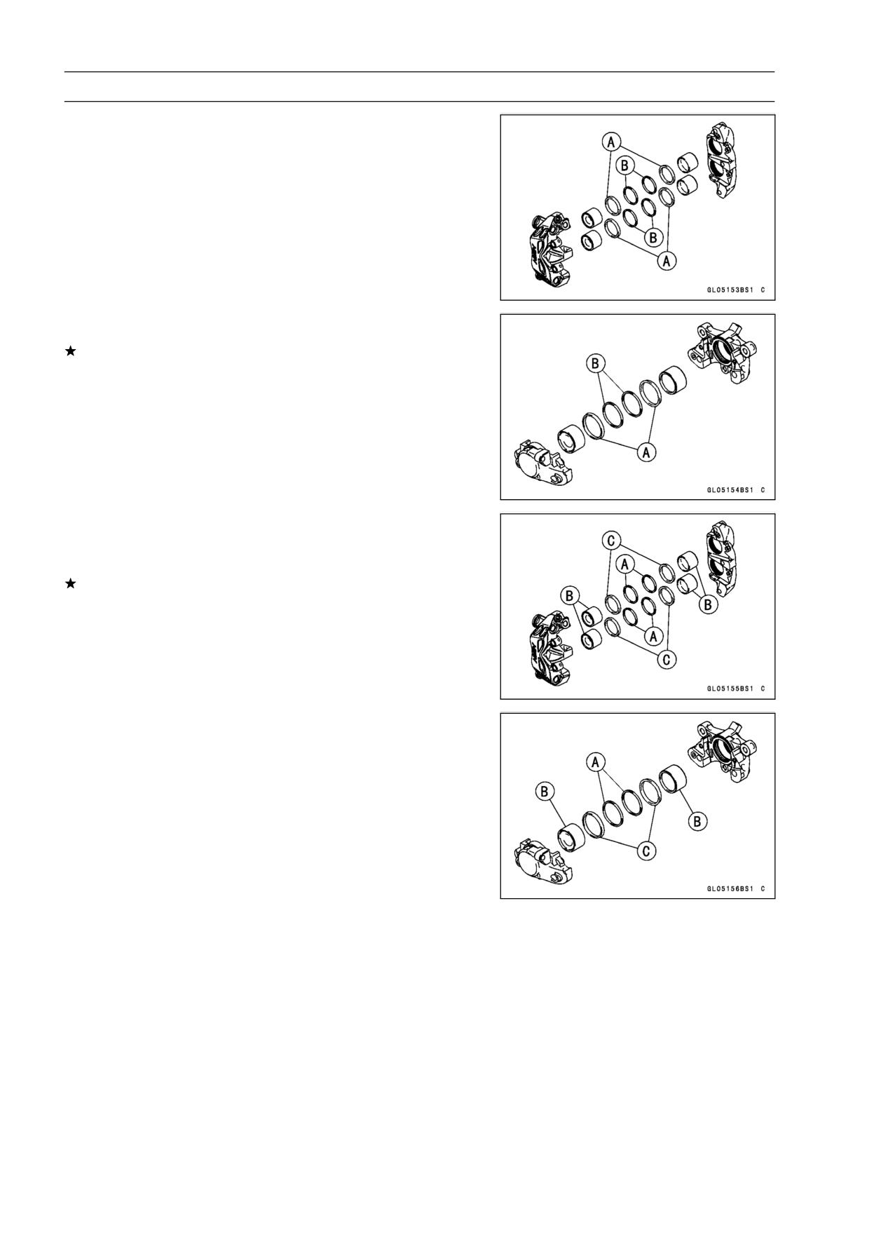
Caliper Fluid Seal Damage
The fluid seal (piston seal) [A] is placed around the pis-
ton to maintain clearance between the pad and the disc. If
the seal is in a poor condition, it could lead the pad to wear
excessively or the brake to drag, which may cause the tem-
perature of the discs or the brake fluid to increase.
• Replace the fluid seal if it exhibits any of the conditions
listed below.
○Brake fluid leakage around the pad.
○Brakes overheat.
○Considerable difference in inner and outer pad wear.
○Seal and piston are stuck together.
If the fluid seal is replaced, replace the dust seal [B] as
well. Also, replace all seals every other time the pads are
changed.
Caliper Dust Seal Damage
• Check that the dust seals [A] are not cracked, worn,
swollen, or otherwise damaged.
If they show any damage, replace the dust seals with new
ones.
Pistons [B]
Fluid Seals [C]
BRAKES 12-19
Calipers
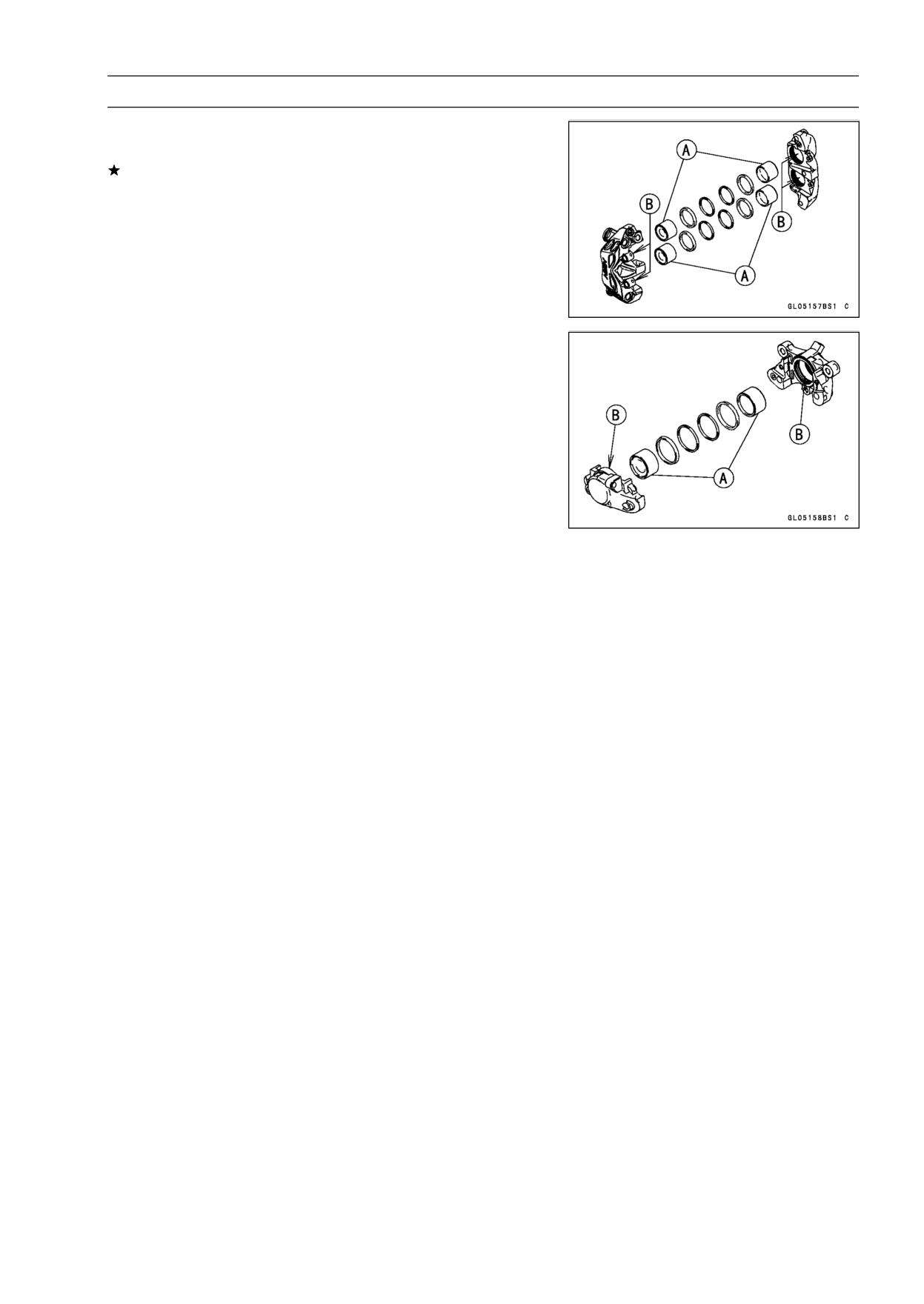
Caliper Piston and Cylinder Damage
• Visually inspect the pistons [A] and cylinder surfaces [B].
Replace the caliper if the cylinder and piston are badly
scores or rusty.
12-20 BRAKES
Brake Pads
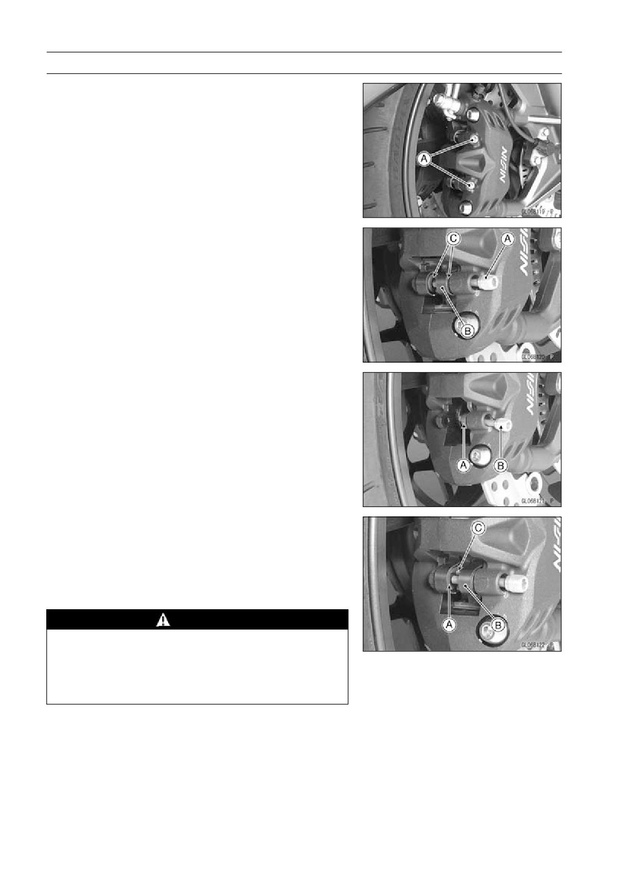
Front Brake Pad Removal
• Loosen the pad pins [A].
• Remove:
Pad Pins [A]
Pad Springs [B]
Brake Pads [C]
Front Brake Pad Installation
• Push the caliper pistons in by hand as far as they will go.
• Install the outside pad [A] and insert the pad pin [B] as
shown in the figure.
• Set:
Inside Pad [A]
Pad Spring [B]
○Pushing the pin holder [C] to hole of the pad and insert
the pad pin.
Torque - Front Brake Pad Pins: 17.2 N·m (1.8 kgf·m, 13 ft·lb)
WARNING
Do not attempt to drive the motorcycle until a full
brake lever is obtained by pumping the brake lever
and the pads are against the disc. The brake will
not function on the first application of the lever if
this is not done.
BRAKES 12-21
Brake Pads
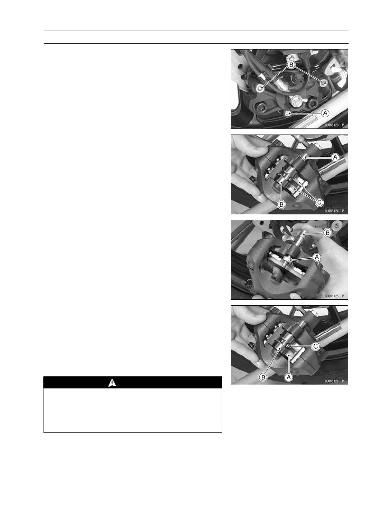
Rear Brake Pad Removal
• Loosen the pad pin [A].
• Unscrew the caliper mounting bolts [B].
• Remove the caliper with the hose installed.
• Remove:
Pad Pin [A]
Pad Spring [B]
Brake Pads [C]
Rear Brake Pad Installation
• Push the caliper pistons in by hand as far as they will go.
• Install the outside pad [A] and insert the pad pin [B] as
shown in the figure.
• Set:
Inside Pad [A]
Pad Spring [B]
○Pushing the pin holder [C] to hole of the pad and insert
the pad pin.
• Install the caliper (see Caliper Installation).
• Tighten the pad pin.
Torque - Rear Brake Pad Pin: 17.2 N·m (1.8 kgf·m, 13 ft·lb)
WARNING
Do not attempt to drive the motorcycle until a full
brake pedal is obtained by pumping the brake pedal
until the pads are against the disc. The brake will
not function on the first application of the pedal if
this is not done.
Brake Pad Wear Inspection
• Refer to the Brake Pad Wear Inspection in the Periodic
Maintenance chapter.
12-22 BRAKES
Master Cylinder
Front Master Cylinder Removal
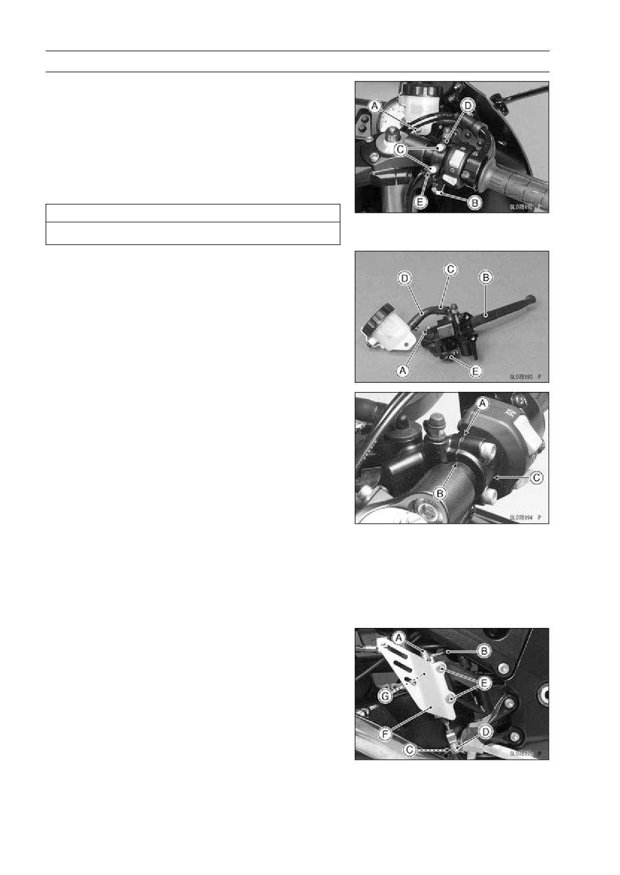
• Remove the reservoir bracket bolt [A].
• Remove the banjo bolt [B] to disconnect the brake hose
from the master cylinder (see Brake Hose Removal/In-
stallation).
• Unscrew the clamp bolts [C], and take off the master cylin-
der [D] as an assembly with the reservoir, brake lever, and
brake switch installed.
• Disconnect the front brake light switch connector [E].
CAUTION
Immediately wash away any brake fluid that spills.
• Remove:
Brake Lever Pivot Bolt [A] and Nut
Brake Lever [B]
Clamp [C] (Slide Out)
Brake Hose [D]
Front Brake Light Switch [E]
Front Master Cylinder Installation
• Set the front master cylinder to match its mating surface
[A] to the punch mark [B] of the handlebar.
• The master cylinder clamp must be installed with the ar-
row mark [C] upward.
• Tighten the upper clamp bolt first, and then the lower
clamp bolt.
Torque - Front Master Cylinder Clamp Bolts: 8.8 N·m (0.90
kgf·m, 78 in·lb)
• Replace the washers that are on each side of the hose
fitting with new ones.
• Tighten:
Torque - Brake Hose Banjo Bolt: 25 N·m (2.5 kgf·m, 18 ft·lb)
• Bleed the brake line (see Brake Line Bleeding).
• Check the brake for good braking power, no brake drag,
and no fluid leakage.
Rear Master Cylinder Removal
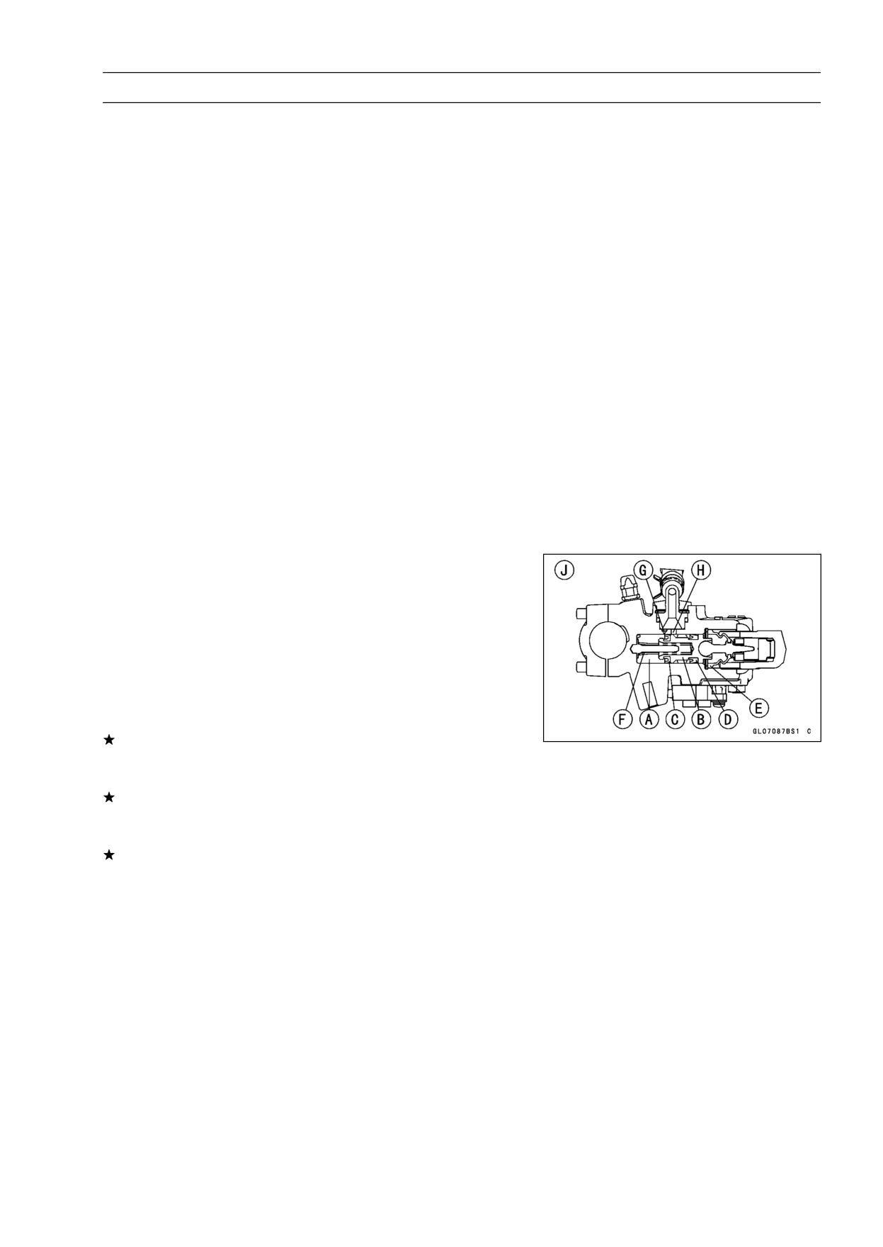
• Unscrew the brake hose banjo bolt [A] and brake hose
[B].
• Remove:
Cotter Pin [C]
Joint Pin [D]
Bolts [E]
Foot Guard [F]
Rear Master Cylinder
• Slide out the clamp [G].
• Pull off the reservoir hose lower end, and drain the brake
fluid into a container.
BRAKES 12-23
Master Cylinder
Rear Master Cylinder Installation
• Replace the cotter pin with a new one.
• Replace the washers that are on each side of hose fitting
with new ones.
• Tighten:
Torque - Rear Master Cylinder Mounting Bolts: 25 N·m (2.5
kgf·m, 18 ft·lb)
Brake Hose Banjo Bolt: 25 N·m (2.5 kgf·m, 18 ft·lb)
• Bleed the brake line (see Brake Line Bleeding).
• Check the brake for good braking power, no brake drag,
and no fluid leakage.
Front Master Cylinder Disassembly
• Refer to the Master Cylinder Rubber Parts Replacement
in the Periodic Maintenance chapter.
Rear Master Cylinder Disassembly
• Refer to the Master Cylinder Rubber Parts Replacement
in the Periodic Maintenance chapter.
Master Cylinder Assembly
• Refer to the Master Cylinder Rubber Parts Replacement
in the Periodic Maintenance chapter.
Master Cylinder Inspection (Visual Inspection)
• Remove the master cylinders (see Front/Rear Master
Cylinder Removal).
• Disassemble the front and rear master cylinders (see
Master Cylinder Rubber Parts Replacement in the Peri-
odic Maintenance chapter).
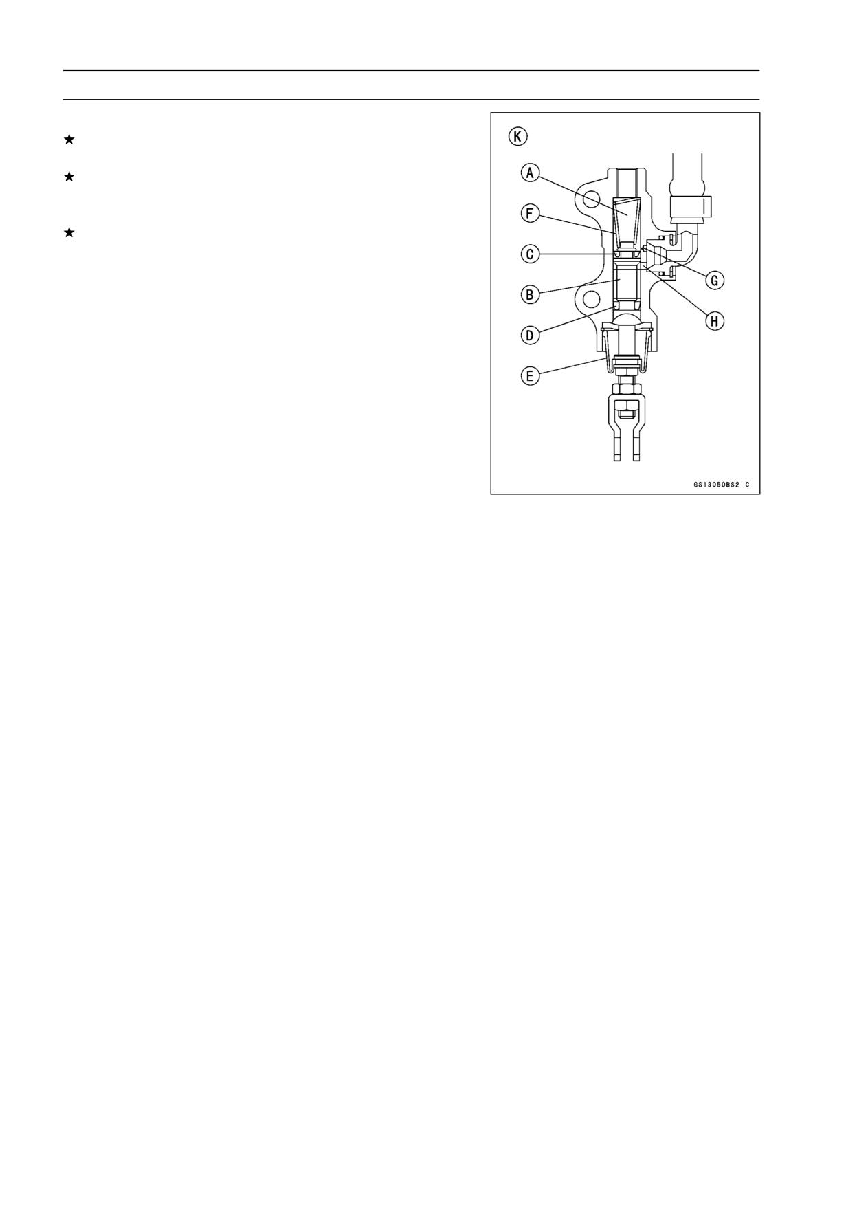
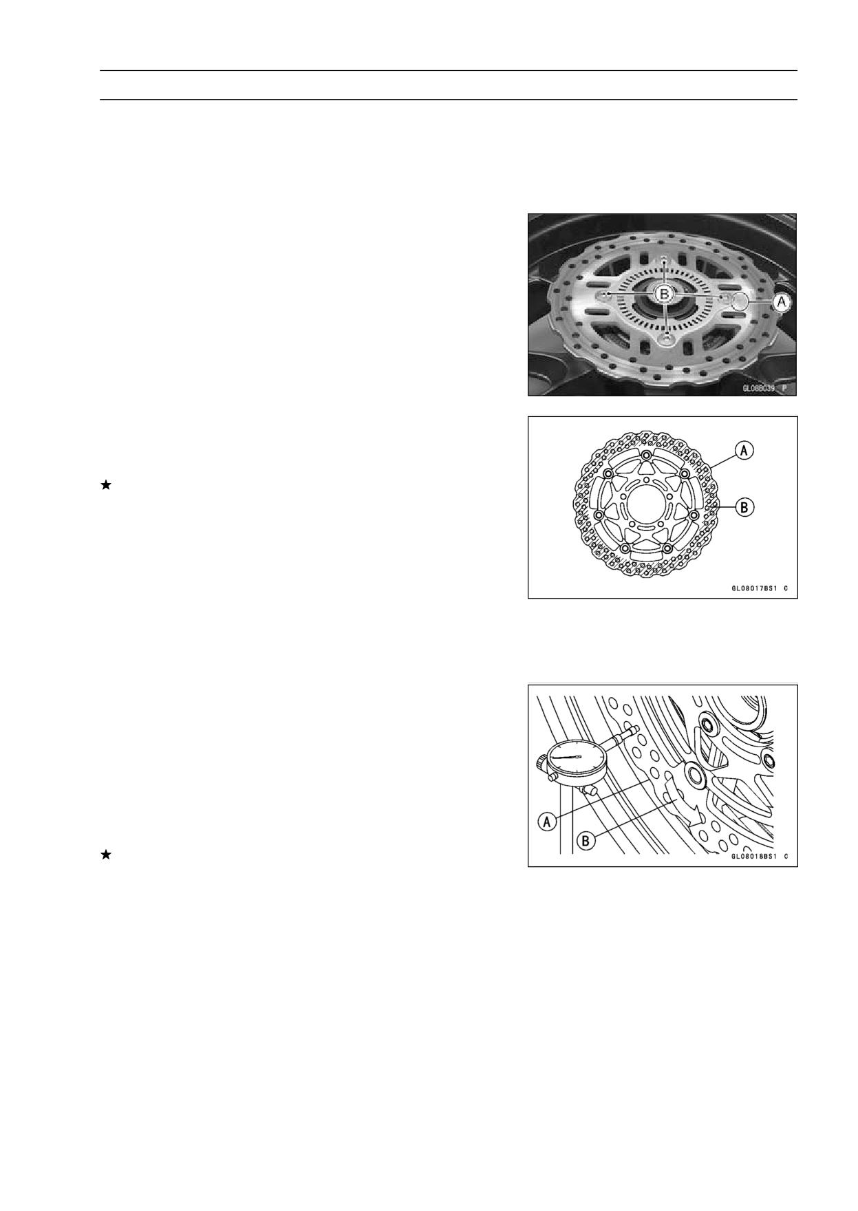
• Check that there are no scratches, rust or pitting on the
inner wall [A] of each master cylinder and on the outside
of each piston [B].
If a master cylinder or piston shows any damage, replace
them.
• Inspect the primary cup [C] and secondary cup [D].
If a cup is worn, damaged softened (rotted), or swollen,
the piston assembly should be replaced to renew the
cups.
If fluid leakage is noted at the brake lever, the piston as-
sembly should be replaced to renew the cups.
Front Master Cylinder [J]
12-24 BRAKES
Master Cylinder
• Check the dust covers [E] for damage.
If they are damaged, replace them.
• Check the piston return spring [F] for any damage.
If the springs are damaged, replace them.
• Check that relief port [G] and supply port [H] are not
plugged.
If the relief port becomes plugged, the brake pads will
drag on the disc. Blow the ports clean with compressed
air.
Rear Master Cylinder [K]
BRAKES 12-25
Brake Disc
Brake Disc Removal
• Remove the wheels (see Front/Rear Wheel Removal in
the Wheels/Tires chapter).
• Unscrew the mounting bolts, and take off the disc.
○Remove the sensor rotor (ZX1400B Models).
Brake Disc Installation
• Install the brake disc on the wheel so that the marked side
[A] faces out.
○Install the sensor rotor on the brake disc so that the
marked side faces out (ZX1400B Models).
• Apply a non-permanent locking agent to the threads of
the rear brake disc mounting bolts [B].
• Tighten:
Torque - Brake Disc Mounting Bolts: 27 N·m (2.8 kgf·m, 20
ft·lb)
Brake Disc Wear
• Measure the thickness of each disc [A] at the point where
it has worn the most.
If the disc has worn past the service limit, replace it.
Measuring Area [B]
Brake Discs Thickness
Standard:
Front
4.8 ∼ 5.2 mm (0.19 ∼ 0.20 in.)
Rear
5.8 ∼ 6.2 mm (0.23 ∼ 0.24 in.)
Service Limit:
Front
4.5 mm (0.18 in.)
Rear
5.5 mm (0.22 in.)
Brake Disc Warp
• Raise the front/rear wheel off the ground.
Special Tools - Jack: 57001-1238
Jack Attachment: 57001-1608
○For front disc inspection, turn the handlebar fully to one
side.
• Set up a dial gauge against the disc [A] as shown and
measure disc runout, while turning [B] the wheel by hand.
If runout exceeds the service limit, replace the disc.
Disc Runout
Standard:
TIR 0.15 mm (0.006 in.) or less
Service Limit:
TIR 0.3 mm (0.01 in.)
12-26 BRAKES
Brake Fluid
Brake Fluid Level Inspection
• Refer to the Brake Fluid Level Inspection in the Periodic
Maintenance chapter.
Brake Fluid Change
• Refer to the Brake Fluid Change in the Periodic Mainte-
nance chapter.
Brake Line Bleeding
The brake fluid has a very low compression coefficient so
that almost all the movement of the brake lever or pedal
is transmitted directly to the caliper for braking action. Air,
however, is easily compressed. When air enters the brake
lines, brake lever or pedal movement will be partially used
in compressing the air. This will make the lever or pedal feel
spongy, and there will be a loss in braking power.
WARNING
Be sure to bleed the air from the brake line when-
ever brake lever or pedal action feels soft or
spongy after the brake fluid is changed, or when-
ever a brake line fitting has been loosened for any
reason.
NOTE
○The procedure to bleed the front brake line is as follows.
Bleeding the rear brake line is the same as for the front
brake.
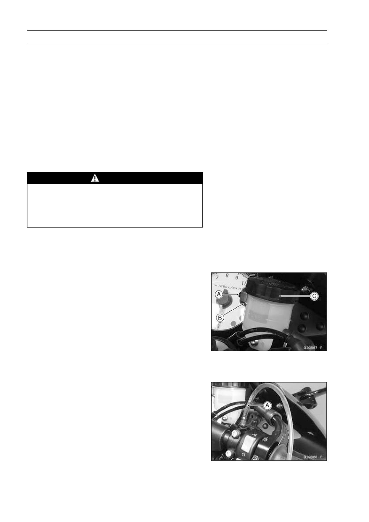
• Remove:
Screw [A]
Clamp [B]
Front Brake Reservoir Cap [C]
Diaphragm Plate
Diaphragm
• Fill the reservoir with fresh brake fluid to the upper level
line in the reservoir.
• Slowly pump the brake lever several times until no air
bubbles can be seen rising up through the fluid from the
holes at the bottom of the reservoir.
○Bleed the air completely from the master cylinder by this
operation.
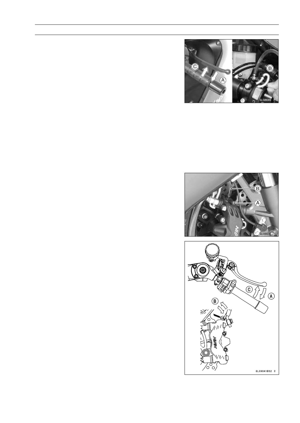
• Remove the rubber cap from the bleed valve on the front
master cylinder.
• Attach a clear plastic hose [A] to the bleed valve, and run
the other end of the hose into a container.
BRAKES 12-27
Brake Fluid
• Bleed the brake line and the master cylinder.
○Repeat this operation until no more air can be seen com-
ing out into the plastic hose.
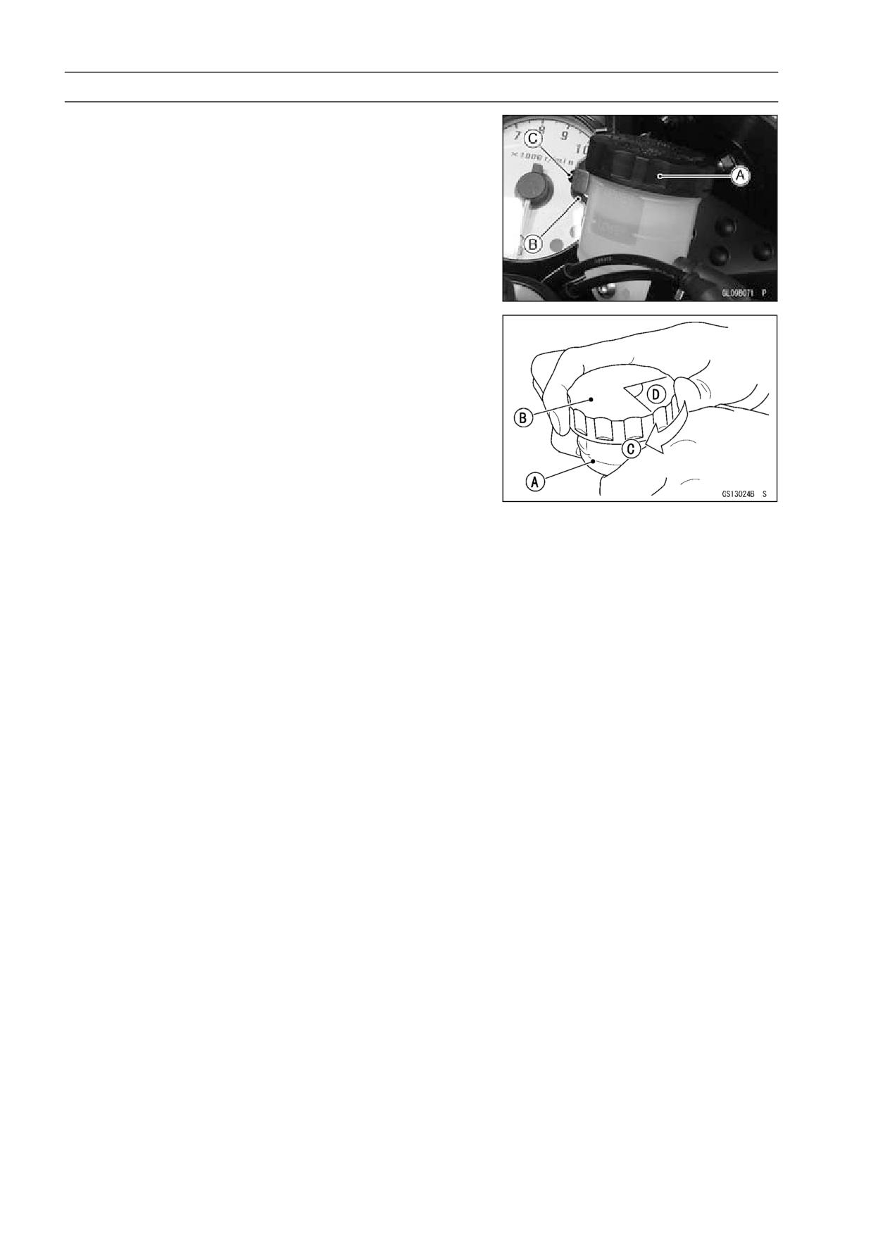
1. Pump the brake lever until it becomes hard, and apply
the brake and hold it [A].
2. Quickly open and close [B] the bleed valve while hold-
ing the brake applied.
3. Release the brake [C].
NOTE
○The fluid level must be checked often during the bleed-
ing operation and replenished with fresh brake fluid as
necessary. If the fluid in the reservoir runs completely
out any time during bleeding, the bleeding operation
must be done over again from the beginning since air
will have entered the line.
• Remove the clear plastic hose.
• Tighten the bleed valve, and install the rubber cap.
Torque - Front Master Cylinder Bleed Valve: 7.8 N·m (0.80
kgf·m, 69 in·lb)
• Remove the rubber cap [A] from the bleed valve on the
caliper.
• Attach a clear plastic hose [B] to the bleed valve, and run
the other end of the hose into a container.
• Bleed the brake line and the caliper.
○Repeat this operation until no more air can be seen com-
ing out into the plastic hose.
1. Pump the brake lever until it becomes hard, and apply
the brake and hold it [A].
2. Quickly open and close [B] the bleed valve while hold-
ing the brake applied.
3. Release the brake [C].
NOTE
○The fluid level must be checked often during the bleed-
ing operation and replenished with fresh brake fluid as
necessary. If the fluid in the reservoir runs completely
out any time during bleeding, the bleeding operation
must be done over again from the beginning since air
will have entered the line.
○Tap the brake hose lightly from the caliper to the reser-
voir for more complete bleeding.
○Front Brake: First bleeding the right caliper then repeat
the above steps for the left caliper.
• Remove the clear plastic hose.
12-28 BRAKES
Brake Fluid
• Install:
Diaphragm
Diaphragm Plate
Front Brake Reservoir Cap [A]
Clamp [B]
Screw [C]
• Follow the procedure below to install the front/rear brake
fluid reservoir cap correctly.
○First, tighten the brake fluid reservoir cap [B] clockwise
[C] by hand until slight resistance is felt indicating that
the cap is seated on the reservoir body, then tighten the
cap an additional 1/6 turn [D] while holding the brake fluid
reservoir body [A].
• Tighten:
Torque - Front Brake Reservoir Cap Stopper Screw:
1.2
N·m (0.12 kgf·m, 11 in·lb)
• Tighten the bleed valve, and install the rubber cap.
Torque - Bleed Valve: 7.8 N·m (0.80 kgf·m, 69 in·lb)
• Check the fluid level (see Brake Fluid Level Inspection in
the Periodic Maintenance chapter).
• After bleeding is done, check the brake for good braking
power, no brake drag, and no fluid leakage.
BRAKES 12-29
Brake Fluid
WARNING
When working with the disc brake, observe the pre-
cautions listed below.
1.
Never reuse old brake fluid.
2.
Do not use fluid from a container that has been left
unsealed or that has been open for a long time.
3.
Do not mix two types and brands of fluid for use in
the brake. This lowers the brake fluid boiling point
and could cause the brake to be ineffective. It may
also cause the rubber brake parts to deteriorate.
4.
Don’t leave the reservoir cap off for any length of
time to avoid moisture contamination of the fluid.
5.
Don’t change the fluid in the rain or when a strong
wind is blowing.
6.
Except for the disc pads and disc, use only disc
brake fluid, isopropyl alcohol, or ethyl alcohol for
cleaning of the brake parts. Do not use any other
fluid for cleaning these parts. Gasoline, engine oil,
or any other petroleum distillate will cause deterio-
ration of the rubber parts. Oil spilled on any part will
be difficult to wash off completely and will eventually
deteriorate the rubber used in the disc brake.
7.
When handling the disc pads or disc, be careful that
no disc brake fluid or any oil gets on them. Clean off
any fluid or oil that inadvertently gets on the pads or
disc with a high-flash point solvent. Do not use one
which will leave an oily residue. Replace the pads
with new ones if they cannot be cleaned satisfacto-
rily.
8.
Brake fluid quickly ruins painted surfaces; any
spilled fluid should be completely wiped up imme-
diately.
9.
If any of the brake line fittings or the bleed valve is
opened at any time, the AIR MUST BE BLED FROM
THE BRAKE LINE.
12-30 BRAKES
Brake Hose
Brake Hose and Pipe Removal/Installation
• Refer to the Brake Hose and Pipe Replacement in the
Periodic Maintenance chapter.
Brake Hose and Pipe Inspection
• Refer to the Brake Hose and Pipe Damage and Instal-
lation Condition Inspection in the Periodic Maintenance
chapter.
BRAKES 12-31
Anti-Lock Brake System (Equipped Models)
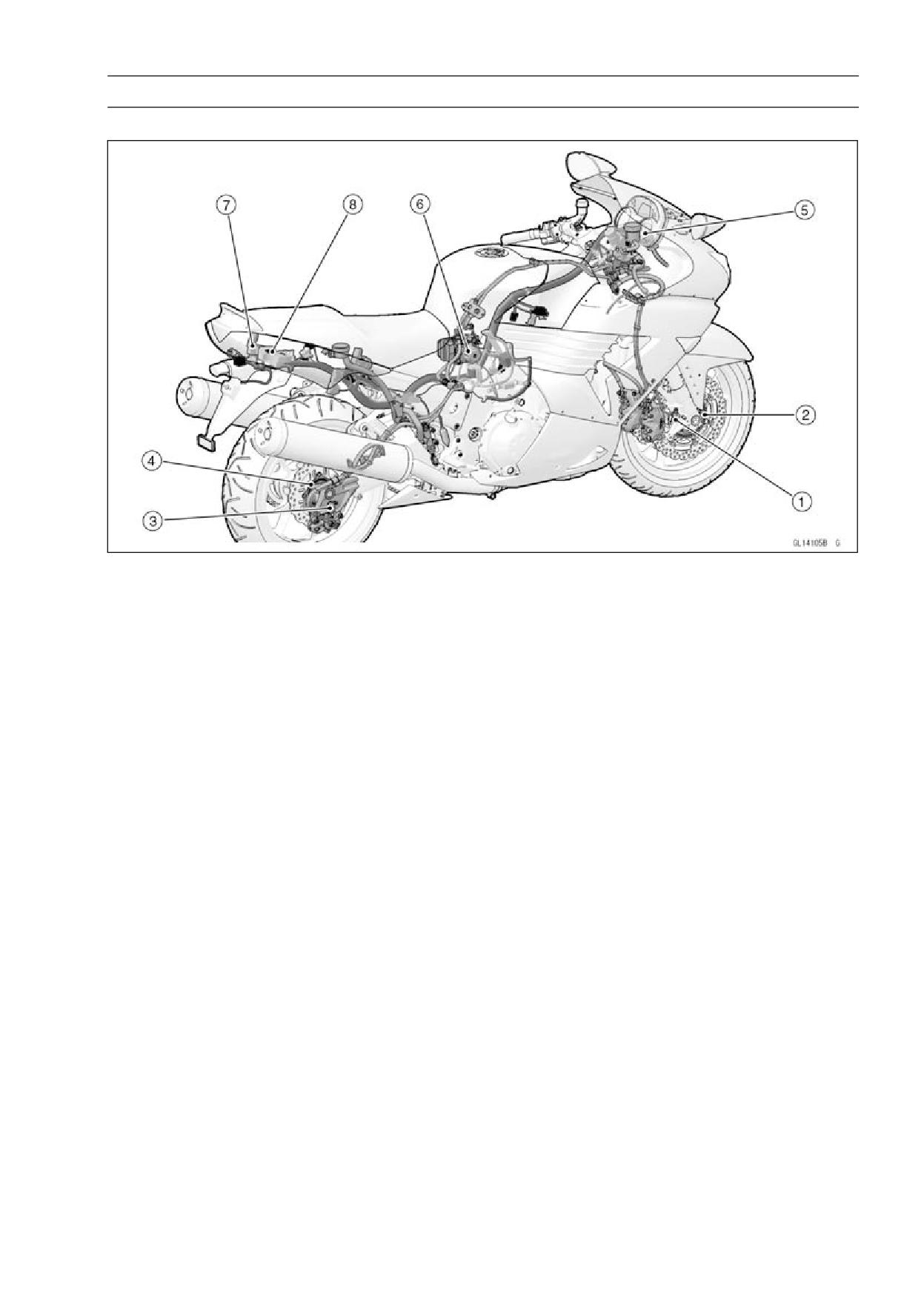
Parts Location
1. Front Wheel Rotation Sensor
2. Front Wheel Rotation Sensor Rotor
3. Rear Wheel Rotation Sensor
4. Rear Wheel Rotation Sensor Rotor
5. ABS Indicator Light (LED)
6. ABS Hydraulic Unit
7. ABS Fuse Box
8. ABS Kawasaki Self-diagnosis System Connector
12-32 BRAKES
Anti-Lock Brake System (Equipped Models)
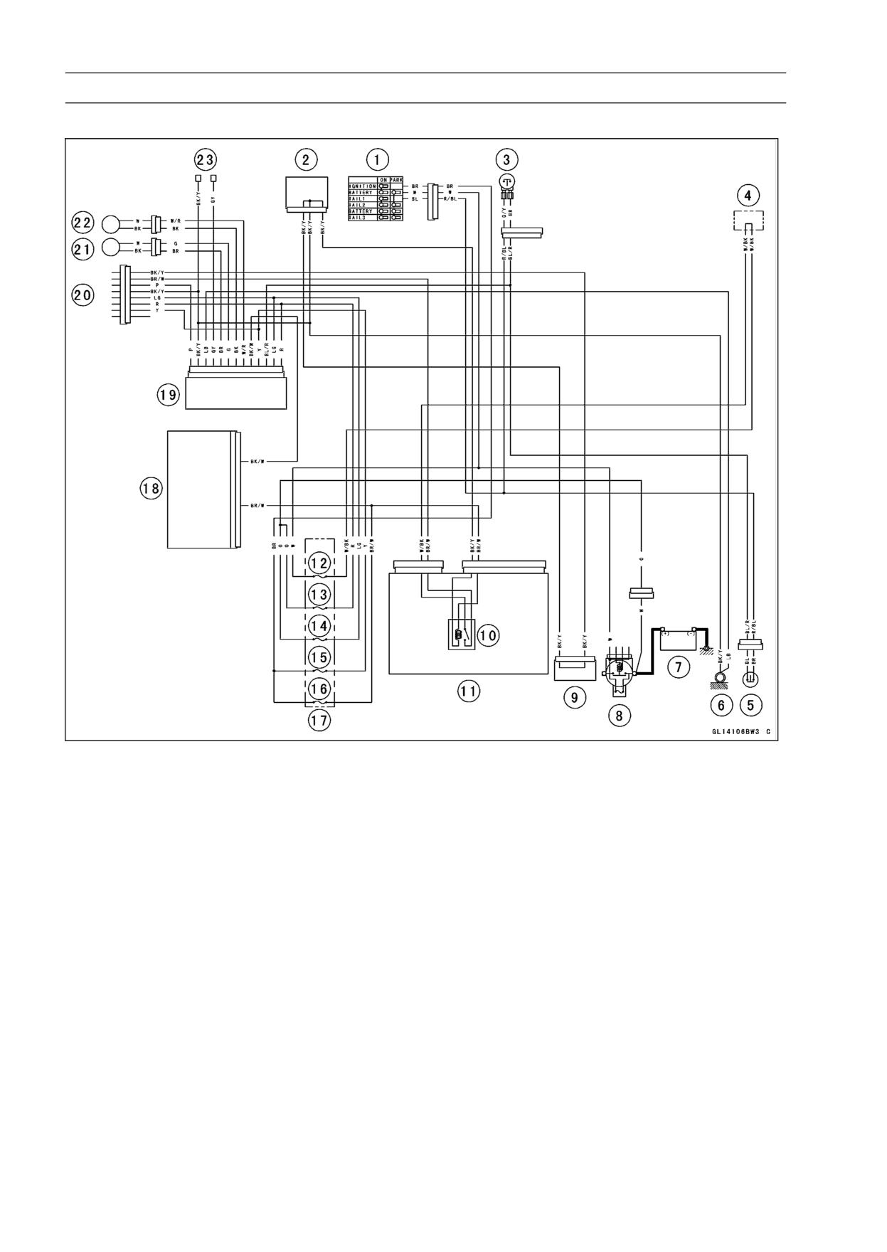
ABS System Wiring Diagram
1. Ignition Switch
2. Joint Connector 1
3. Front Brake Switch
4. Water-proof Joint 1
5. Rear Brake Switch
6. Frame Ground
7. Battery 12 V 14 Ah
8. Main Fuse 30 A
9. Joint Connector 2
10. Main Relay
11. Relay Box
12. ECU Fuse 15 A
13. ABS Motor Relay Fuse 30 A
14. ABS Solenoid Valve Relay Fuse 20 A
15. ABS ECU Fuse 10 A
16. Ignition Fuse 10 A
17. Fuse Box 2
18. Meter Unit
19. ABS Hydraulic Unit
20. ABS Kawasaki Self-diagnosis System Connector
21. Front Wheel Rotation Sensor
22. Rear Wheel Rotation Sensor
23. ABS Self-diagnosis Terminal
BRAKES 12-33
Anti-Lock Brake System (Equipped Models)
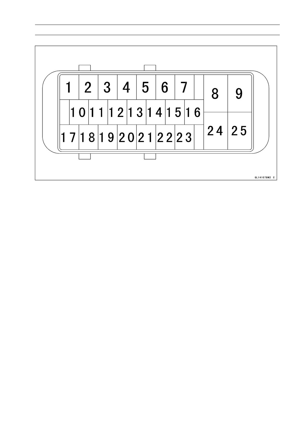
Terminal Names
1. Unused
2. Power Supply to Rear Wheel Rotation Sensor
3. Front Wheel Rotation Sensor Signal
4. Front and Rear Brake Light Switch
5. Unused
6. Unused
7. Unused
8. Power Supply to ABS Solenoid Valve Relay
9. Power Supply to ABS Motor Relay
10. ABS Kawasaki Self-diagnosis System Terminal
11. Unused
12. Power Supply to Front Wheel Rotation Sensor
13. ABS Self-diagnosis Terminal
14. Unused
15. Unused
16. Power Supply
17. Unused
18. Rear Wheel Rotation Sensor Signal
19. Unused
20. Unused
21. ABS Indicator Light (LED)
22. Unused
23. Unused
24. Ground
25. Ground to Motor
12-34 BRAKES
Anti-Lock Brake System (Equipped Models)
ABS Servicing Precautions
There are a number of important precautions that should
be followed servicing the ABS system.
○This ABS system is designed to be used with a 12 V
sealed battery as its power source. Do not use any
other battery except for a 12 V sealed battery as a power
source.
○Do not reverse the battery cable connections. This will
damage the ABS hydraulic unit.
○To prevent damage to the ABS parts, do not disconnect
the battery cables or any other electrical connections
when the ignition switch is ON or while the engine is
running.
○Take care not to short the leads that are directly con-
nected to the battery positive (+) terminal to the chassis
ground.
○Do not turn the ignition switch ON while any of the ABS
electrical connectors are disconnected. The ABS hy-
draulic unit memorizes service codes.
○Do not spray water on the electrical parts, ABS parts, con-
nectors, leads and wiring.
○If a transceiver is installed on the motorcycle, make sure
that the operation of the ABS system is not influenced
by electric wave radiated from the antenna. Locate the
antenna as far as possible away from the ABS hydraulic
unit.
○Whenever the ABS electrical connections are to be dis-
connected, first turn off the ignition switch.
○The ABS parts should never be struck sharply, as with
a hammer, or allowed to fall on a hard surface. Such a
shock to the parts can damage them.
○The ABS parts cannot be disassembled. Even if a fault is
found, do not try to disassemble and repair the ABS parts,
replace it.
○The ABS has many brake lines, pipes, and leads. And
the ABS cannot detect problems with the conventional
braking system (brake disc wear, unevenly worn brake
pad, and other mechanical faults). To prevent trouble,
check the brake lines and pipes for correct routing and
connection, the wiring for correct routing, and the brakes
for proper braking power. Be sure to check for fluid leak-
age, and bleed the brake line thoroughly.
WARNING
If any of the brake line fittings, including the ABS
hydraulic unit joint nuts, or the bleed valve is
opened at any time, the air must be bled completely
from the brake line.
CAUTION
Do not ride the motorcycle with air in the brake line,
or the ABS could malfunction.
BRAKES 12-35
Anti-Lock Brake System (Equipped Models)
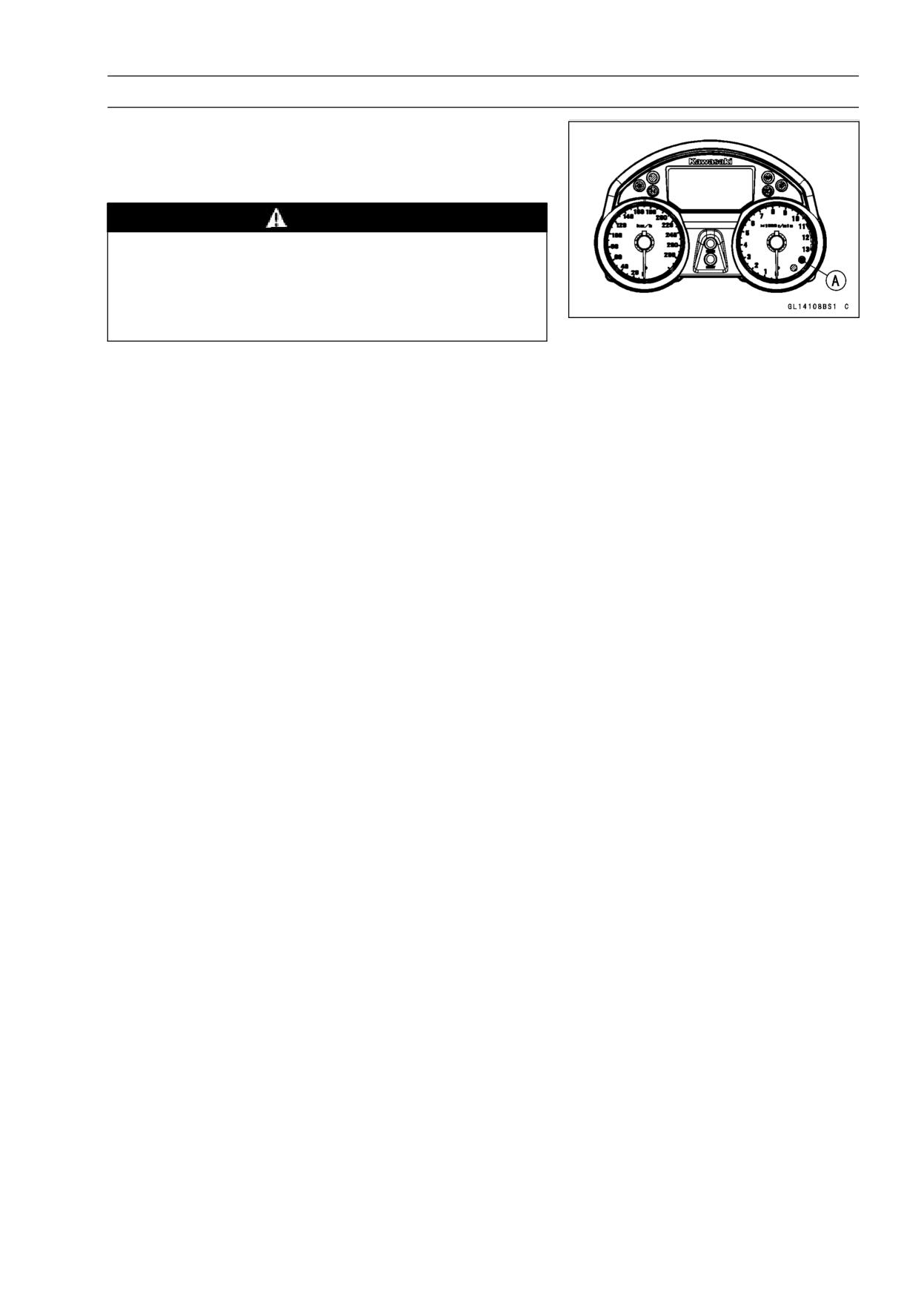
○The ABS indicator light (LED) [A] may light if the tire pres-
sure is incorrect, a non-recommended tire is installed, or
the wheel is deformed. If the indicator light lights, remedy
the problem and clear the service code.
WARNING
Use of non-recommended tires may cause malfunc-
tioning of ABS and can lead to extended braking
distance. The rider could have an accident as a re-
sult. Always use recommended standard tires for
this motorcycle.
○The ABS indicator light (LED) may come on if the engine
is run with the motorcycle on its stand and the transmis-
sion in gear. If the indicator light comes on, just turn the
ignition switch OFF, then clear service code 42, which in-
dicates a “Faulty front wheel rotation sensor”.
○When the ABS operates, the ABS makes noise and the
rider feels the reaction force on the brake lever and brake
pedal. This is a normal condition. It informs the rider that
the ABS is operating normally.
○Service codes detected once by the ABS hydraulic unit
will be memorized in the ABS hydraulic unit. Therefore,
after maintenance work is finished, be sure to erase the
service codes. Do not erase the service codes during
troubleshooting. Wait until all the checks and repair work
are finished to prevent duplication of previous service
codes and unnecessary maintenance work.
○Before delivering the motorcycle to the customer, be
sure to erase any service codes which might be stored in
the ABS hydraulic unit. Using the self-diagnosis feature,
make sure that the ABS indicator light (LED) lights. A
fully charged battery is a must for conducting reliable
self-diagnosis. Test run the motorcycle at a speed of
more than 20 km/h (12 mph) to see that the ABS indicator
light (LED) does not come on. Finally, test run the mo-
torcycle at a speed of more than 30 km/h (20 mph) and
brake suddenly to see that the motorcycle stops without
loss of steering control and the ABS operates normally
(The reaction force generated is felt in the brake lever
and pedal.). This completes the final inspection.
○Color Codes:
BK: Black
G: Green
P: Pink
BL: Blue
GY: Gray
PU: Purple
BR: Brown
LB: Light Blue
R: Red
CH: Chocolate
LG: Light Green
W: White
DG: Dark Green
O: Orange
Y: Yellow
12-36 BRAKES
Anti-Lock Brake System (Equipped Models)
ABS Troubleshooting Outline
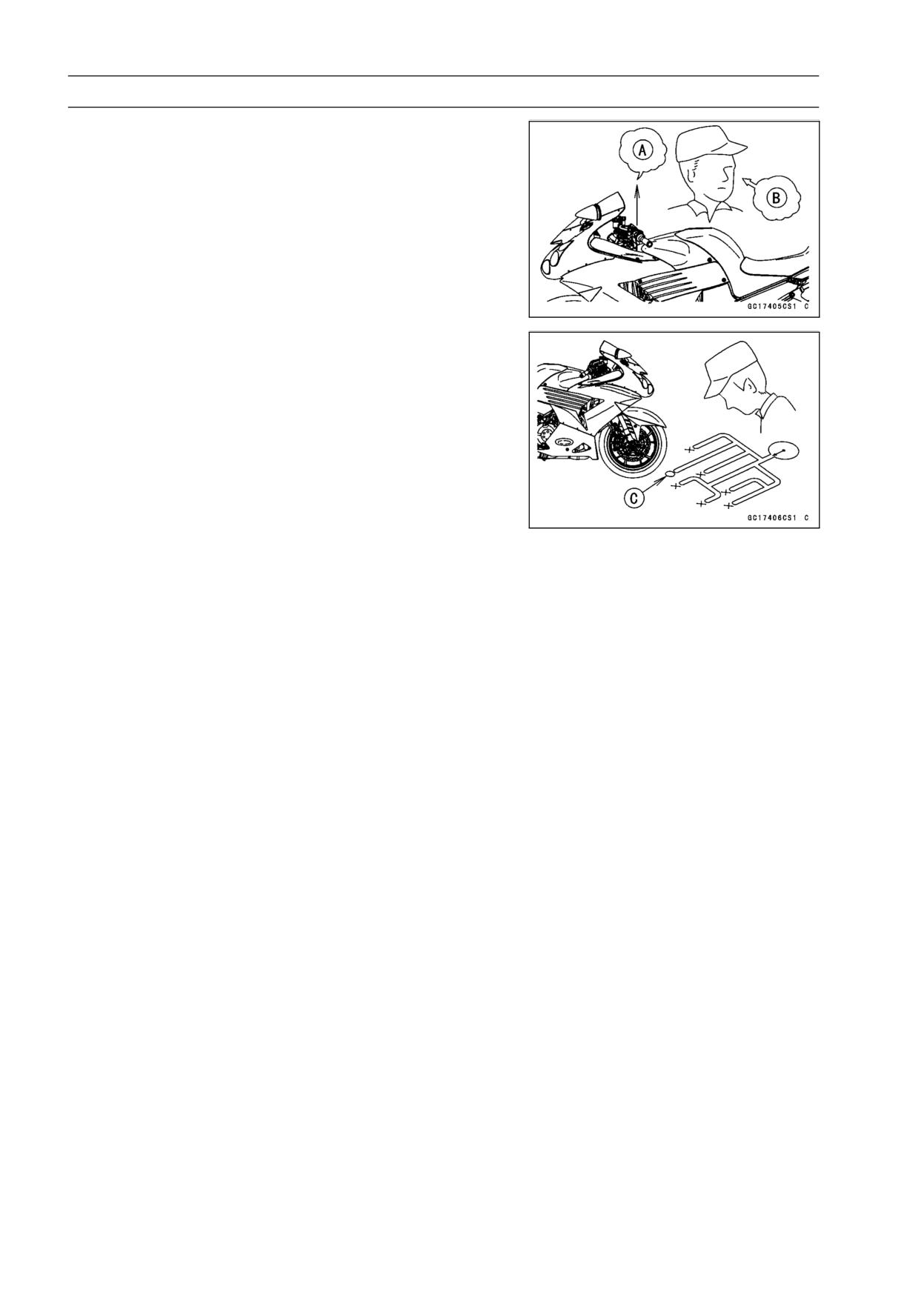
When an abnormality in the system occurs, the ABS in-
dicator light (LED) lights up to alert the rider. In addition,
the nature of the fault is stored in the memory of the ABS
hydraulic unit and when in the self-diagnosis mode, the ser-
vice code [A] is indicated by the number of times the ABS
indicator light (LED) blinks. The service codes stored in
memory are not erased until the mode has been changed
to the fault erase mode after the fault has been corrected.
Therefore, after correcting the problem, always erase the
service codes and then run the self-diagnosis program to
confirm normal signal output. When, due to a malfunction,
the ABS indicator light (LED) remains lit, get a thorough
understanding of the background before starting the repair
work. Ask the rider about the conditions [B] under which
the problem occurred and try to determine the cause [C].
Do not rely solely on the ABS self-diagnosis function, use
common sense; check the brakes for proper braking power,
and brake fluid level, search for leaks, etc.
Even when the ABS is operating normally, the ABS indi-
cator light (LED) may light up under the conditions listed be-
low. Turn the ignition switch OFF to stop the indicator light.
If the motorcycle runs without erasing the service code, the
light may light up again.
○After continuous riding on a rough road.
○When the engine is started with the stand raised and the
transmission engaged, and the rear wheel turns.
○When accelerating so abruptly that the front wheel leaves
the ground.
○When the ABS has been subjected to strong electrical
interference.
○When tire pressure is abnormal. Adjust tire pressure.
○When a tire different in size from the standard size is being
used. Replace with standard size.
○When the wheel is deformed. Replace the wheel.
Much of the ABS troubleshooting work consists of con-
firming continuity of the wiring. The ABS parts are assem-
bled and adjusted by the manufacturer, so there is no need
to disassemble or repair them. Replace the ABS hydraulic
unit.
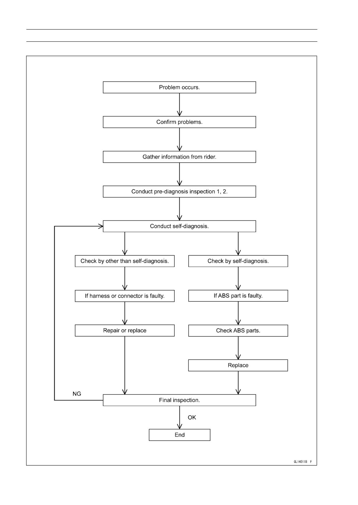
The basic troubleshooting procedures are listed below.
• Carry out pre-diagnosis inspections as a preliminary in-
spection.
• Determine the fault using the self-diagnosis function.
• Check wiring and connections from the ABS hydraulic
unit connector to the suspected faulty ABS part, using the
hand tester.
Special Tool - Hand Tester: 57001-1394
BRAKES 12-37
Anti-Lock Brake System (Equipped Models)
• Visually inspect the wiring for signs of burning or fraying.
If any wiring is poor, replace the damaged wiring.
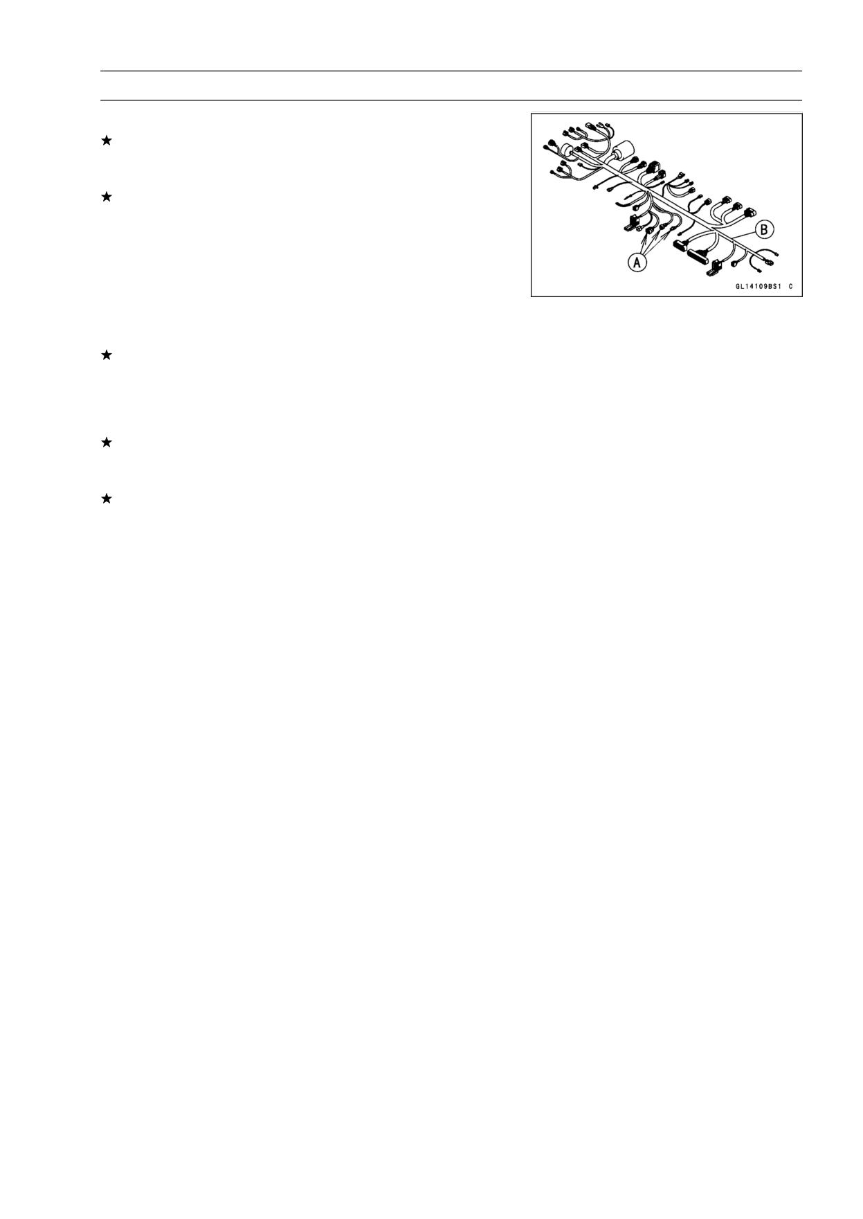
• Pull each connector [A] apart and inspect it for corrosion,
dirt and damage.
If the connector is corroded or dirty, clean it carefully. If it
is damaged, replace it.
• Check the wiring for continuity.
○Use the wiring diagram to find the ends of the lead which
is suspected of being a problem.
○Connect the hand tester between the ends of the leads.
Special Tool - Hand Tester: 57001-1394
○Set the tester to the × 1 Ω range, and read the tester.
If the tester does not read 0 Ω, the lead is defective. Re-
place the main harness [B] if necessary.
• Narrow down suspicious parts and close in on the faulty
ABS part by repeating the continuity tests.
If no abnormality is found in the wiring or connectors, the
ABS parts are the next likely suspects. Check each part
one by one.
If an abnormality is found, replace the affected ABS part.
12-38 BRAKES
Anti-Lock Brake System (Equipped Models)
ABS Diagnosis Flow Chart
BRAKES 12-39
Anti-Lock Brake System (Equipped Models)
Inquiries to Rider
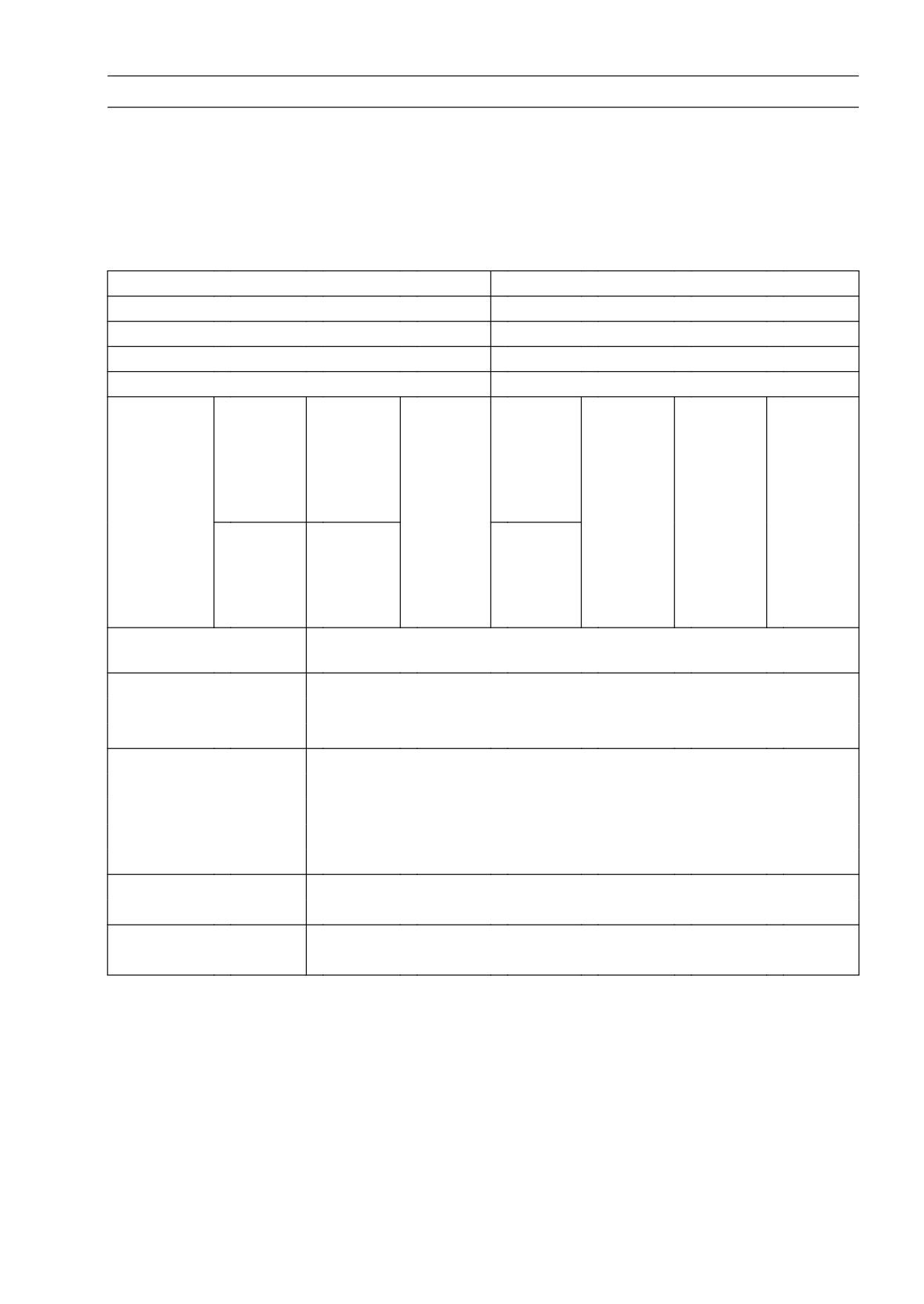
○Each rider reacts to problems in different ways, so it is important to confirm what kind of condition
the rider is dissatisfied with.
○Try to find out exactly what problem occurs under exactly what conditions by asking the rider; know-
ing this information may help you reproduce the problem in the shop.
○The diagnosis sheet will help prevent you from overlooking any keys, so always use it.
Sample Diagnosis Sheet
Rider name:
Registration No. (license plate No.):
Year of initial registration:
Model:
Engine No.:
Frame No.:
Date problem occurred:
Frequency:
Weather:
Mileage:
□ Brake
□ Indicator
□
Braking
□ Abnor-
□
ABS not
□
ABS
□
ABS op-
lever
light
distance
mal
working
works
erating
vibration
blinks
too long
brake
but
too fre-
or noise
lever
indicator
quently
move-
light
Phenome-
ment
doesn’t
non
light up
□ Pedal
□ Indicator
□ Abnor-
vibration
light
mal
or noise
remains
pedal
lit up
move-
ment
Engine conditions at
□ At start-up
□ After starting
□ At 5 000
r/min (rpm)
problem
or more
Road conditions
□ Slippery road
(□ snow,
□ gravel,
□ other
)
□ Rough surface
□ Other
Driving conditions
□ High-speed cornering
□ Driving 10 km/h (6 mph) or above
□ Driving below 10 km/h (6 mph)
□ When stopping
□ When turning
Brake application
□ Gradual
□ Abrupt
Other conditions
□ Large brake lever stroke
□ Large pedal stroke
12-40 BRAKES
Anti-Lock Brake System (Equipped Models)
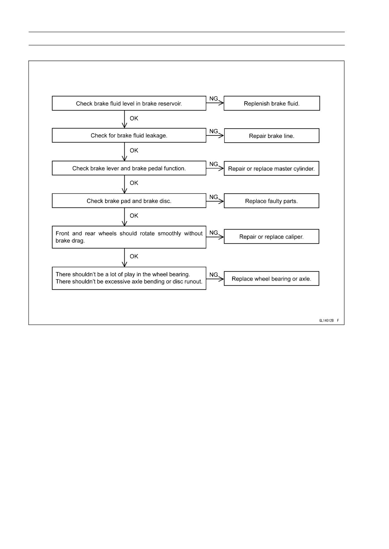
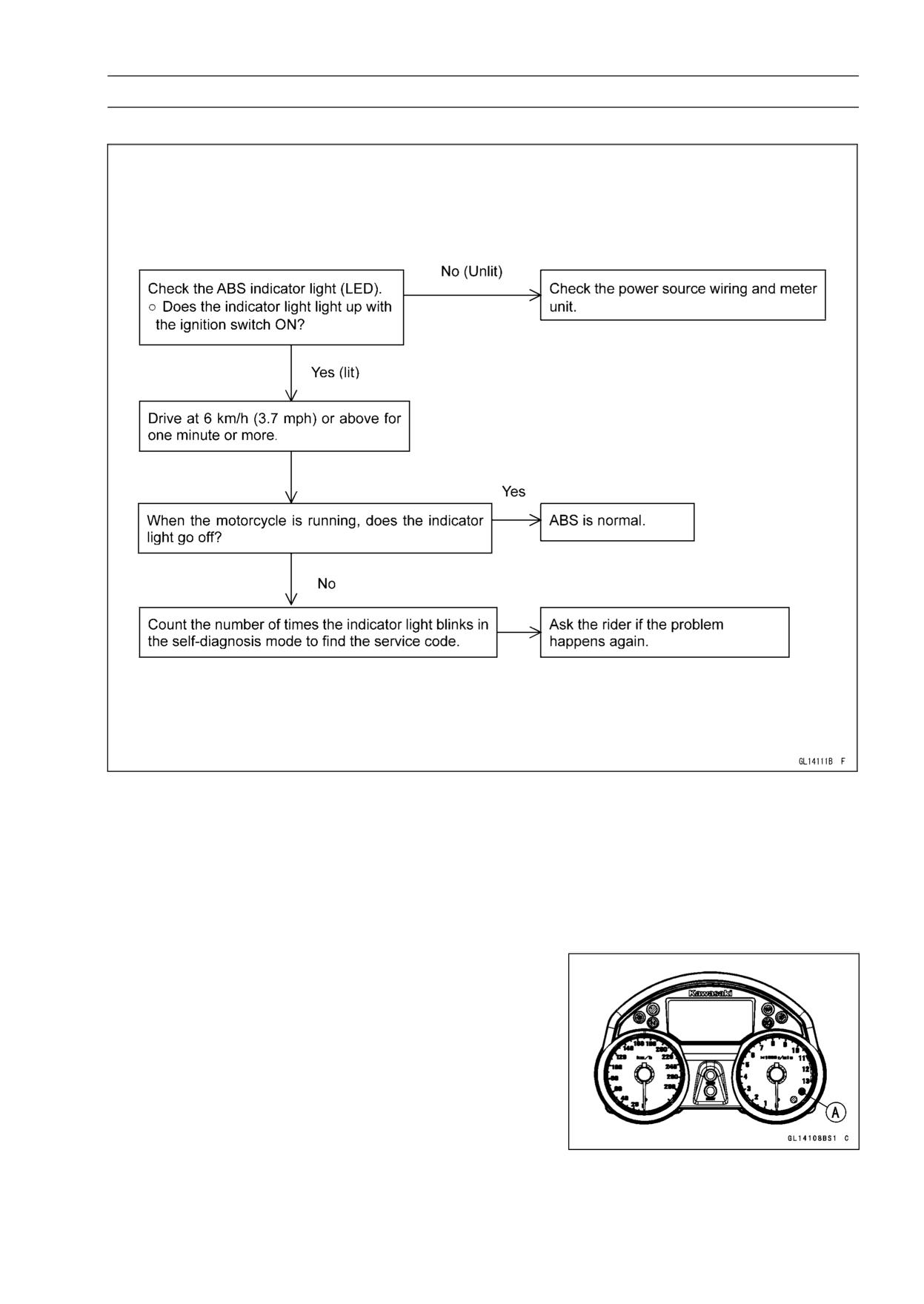
Pre-Diagnosis Inspection 1
BRAKES 12-41
Anti-Lock Brake System (Equipped Models)
Pre-Diagnosis Inspection 2
Self-diagnosis Outline
When the indicator light has blinked or come on, the ABS hydraulic unit memorizes and stores the
service code for the service person to troubleshoot easily. The service code memory is powered
directly by the battery and cannot be canceled by the ignition switch.
The ABS hydraulic unit can memorize up to all service codes (14 codes). Further service codes
are memorized after erasing the preceding all service codes (14 codes). If there is no fault, the ABS
indicator light (LED) lights, indicating that “The ABS is normal”.
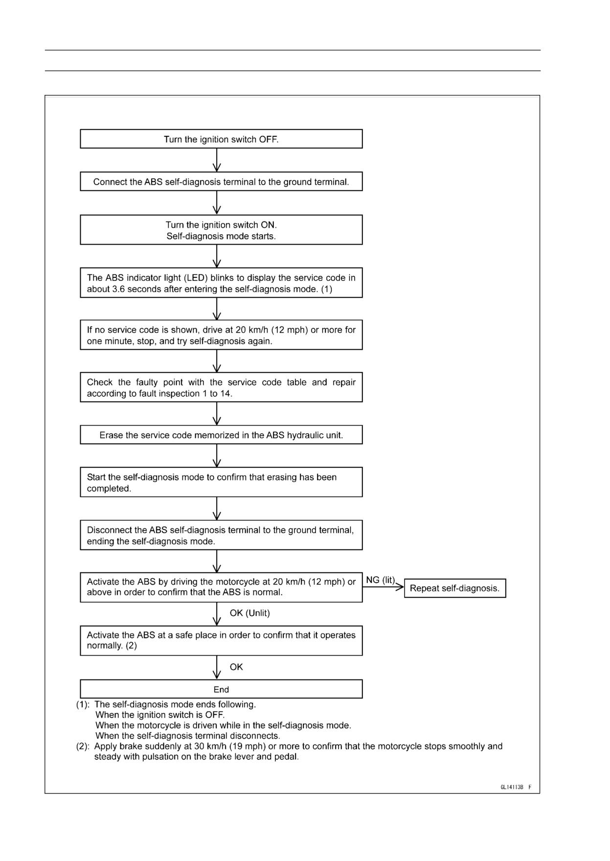
Self-diagnosis Procedures
○When a problem occurs with the ABS system, the ABS
indicator light (LED) [A] lights.
NOTE
○Use a fully charged battery when conducting
self-diagnosis. Otherwise, the light blinks very slowly
or doesn’t blink.
○The motorcycle is stopped.
○Keep the self-diagnosis terminal grounded during self
-diagnosis, with an auxiliary lead.
12-42 BRAKES
Anti-Lock Brake System (Equipped Models)
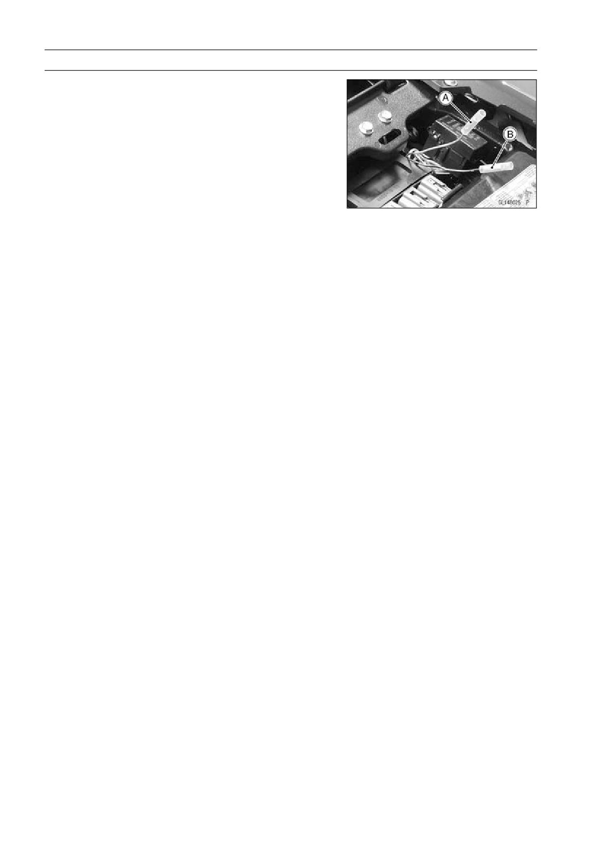
• Remove the seat (see Seat Removal in the Frame chap-
ter).
• Ground the self-diagnosis terminal [A] (Gray) to the
ground terminal [B] (Black/Yellow), using a lead.
• Turn on the ignition switch.
○Count the blinks of the light to read the service code.
Keep the auxiliary lead ground until you finish reading the
service code.
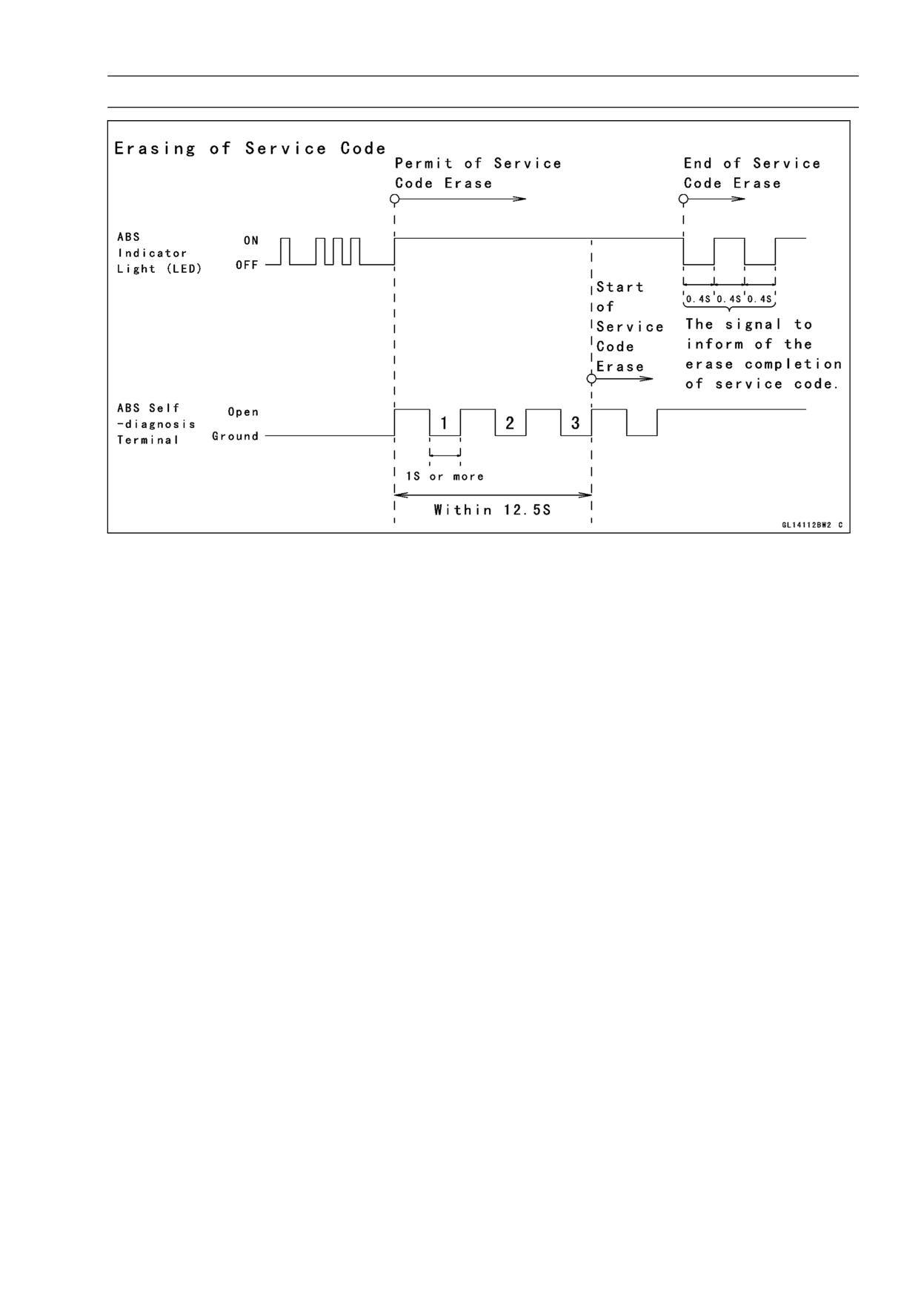
Service Code Clearing Procedures
• Start the service code erase mode with the following pro-
cedure.
○The erase mode starts when the ABS self-diagnosis ter-
minal is disconnected from the ground terminal after start-
ing the self-diagnosis mode.
○The service code can be erased by grounding and un-
grounding (each time for at least one second) the ABS
self-diagnosis terminal three times or more within about
12.5 seconds after starting the erase mode.
○The ABS indicator light (LED) remains lit during the erase
mode.
○After erasing, the ABS indicator light (LED) blinks and
lights.
○Once erasing is finished, enter the self-diagnosis mode
again to confirm that the service codes have been
erased. If the ABS has been reset and all codes have
been erased, the ABS indicator light (LED) lights.
BRAKES 12-43
Anti-Lock Brake System (Equipped Models)
12-44 BRAKES
Anti-Lock Brake System (Equipped Models)
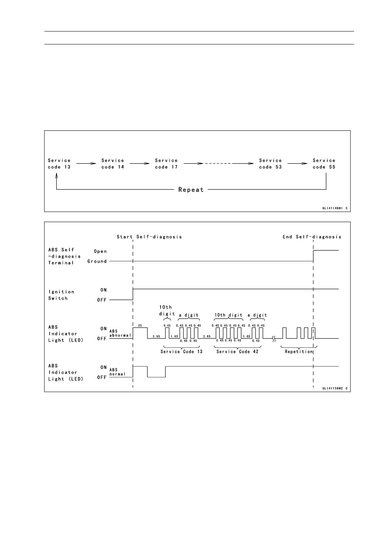
Self-diagnosis Flow Chart
BRAKES 12-45
Anti-Lock Brake System (Equipped Models)
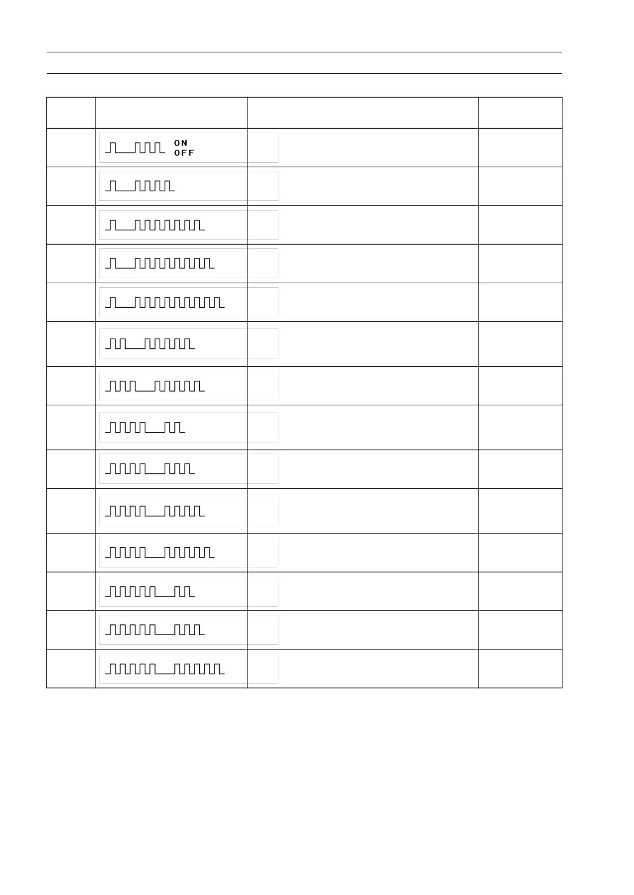
How to Read Service Codes
○Service codes are shown by a series of long and short blinks of the ABS indicator light (LED) as
shown below.
○Read 10th digit and unit digit as the ABS indicator light (LED) blinks.
○When there are a number of faults, a maximum of all service codes (14 codes) can be stored and
the display will begin starting from the small number code entered.
○For the display pattern, first the smallest number code is shown, next up to all service codes (14
codes) starting with the last one stored, then the display is repeated from the smallest number code
once again.
○If there is no fault, the ABS indicator light (LED) lights as shown in the figure.
How to Erase Service Codes
○Even if the ignition switch is turned OFF, the battery or the ABS hydraulic unit are disconnected, all
service codes remain in the ABS hydraulic unit.
○Refer to the Service Code Clearing Procedure for the service code erasure.
12-46 BRAKES
Anti-Lock Brake System (Equipped Models)
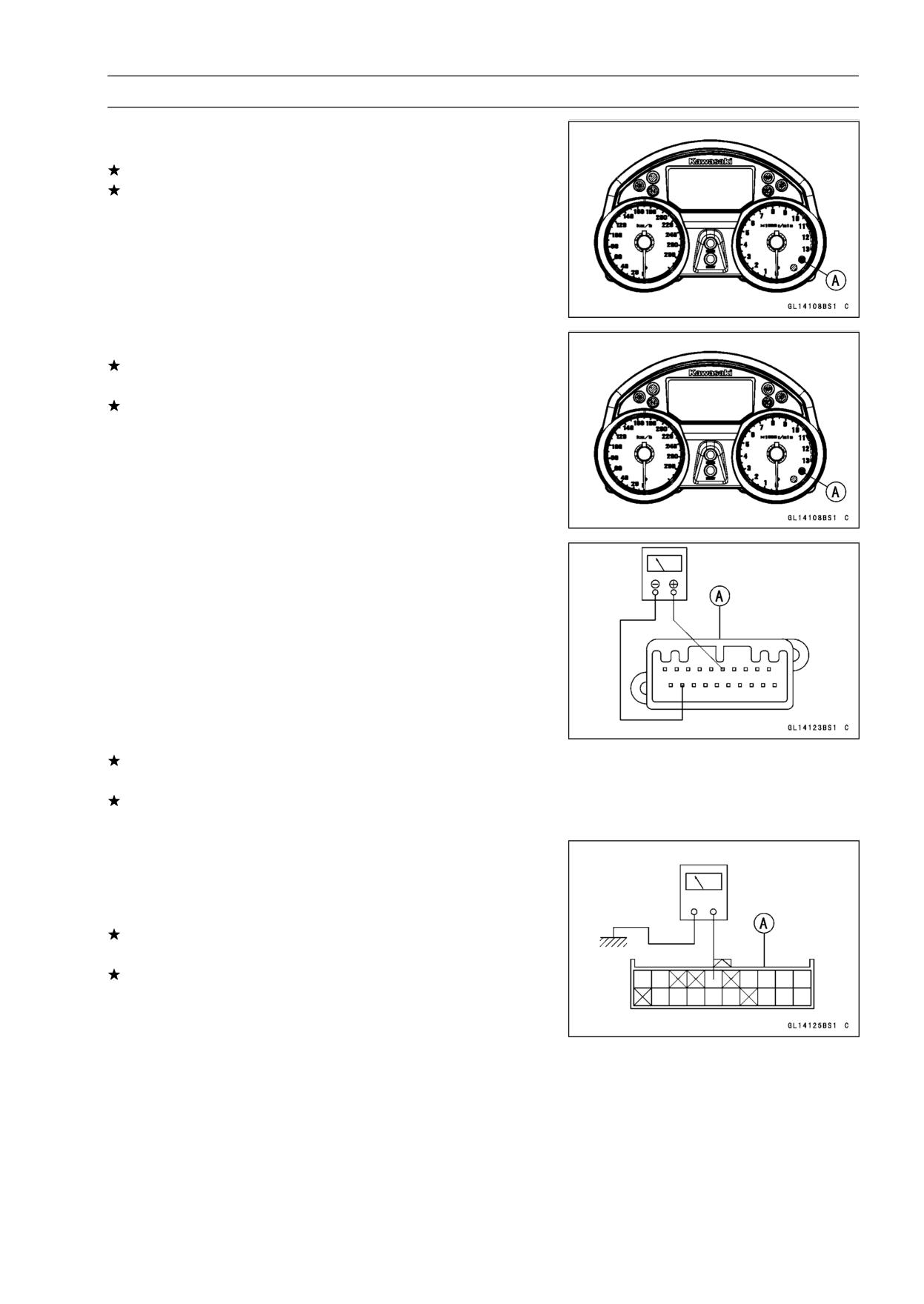
Service Code Table
Service
ABS Indicator Light (LED)
Problems
Light State
Code
Rear inlet solenoid valve trouble (shorted or
13
ON
open, stuck valve (ON))
Rear outlet solenoid valve trouble (shorted
14
ON
or open, stuck valve (ON))
Front inlet solenoid valve trouble (shorted
17
ON
or open, stuck valve (ON))
Front outlet solenoid valve trouble (shorted
18
ON
or open, stuck valve (ON))
ABS solenoid valve relay trouble (wiring
19
ON
shorted or open, stuck relay (ON or OFF))
Front, rear tire abnormal (substandard
25
tire, deformation wheel, sensor rotor teeth
ON
number wrong)
ABS motor relay trouble (wiring shorted,
35
ON
open or lock, stuck relay (ON or OFF)
Front wheel rotation sensor signal abnormal
42
(sensor or rotor missing, too large
ON
clearance, rotor tooth worn or missing)
Front wheel rotation sensor wiring abnormal
43
ON
(wiring shorted or open)
Rear wheel rotation sensor signal abnormal
44
(sensor or rotor missing, too large
ON
clearance, rotor tooth worn or missing)
Rear wheel rotation sensor wiring abnormal
45
ON
(wiring shorted or open)
Power supply voltage abnormal
52
ON
(under-voltage)
Power supply voltage abnormal
53
ON
(over-voltage)
55
ECU trouble (ECU operation abnormal)
ON
BRAKES 12-47
Anti-Lock Brake System (Equipped Models)
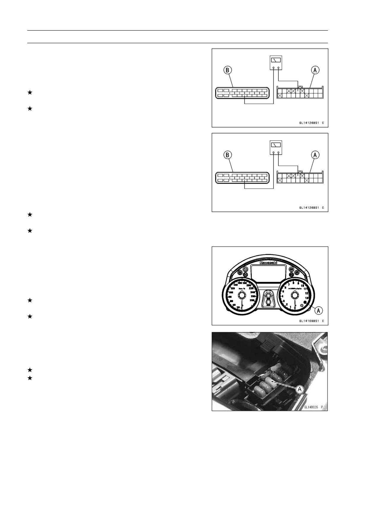
ABS Indicator Light (LED) Inspection
• Turn the ignition switch ON.
If the ABS indicator light (LED) [A] lights, it is normal.
If the ABS indicator light (LED) does not light, go to step
“ABS Indicator Light (LED) is Unlit (When the Ignition
Switch turned to ON)”.
• Turn the ignition switch OFF.
If the ABS indicator light (LED) [A] does not light, it is
normal.
If the ABS indicator light (LED) lights, go to step “ABS In-
dicator Light (LED) Lights (When the Motorcycle is Run-
ning, - No Service Code)”.
ABS Indicator Light (LED) is Unlit (When the
Ignition Switch turned to ON)
• Do the 1st step test.
○Check the terminal voltage between the black/white lead
terminal of the meter connector [A] and ground.
Special Tool - Hand Tester: 57001-1394
○Turn the ignition switch ON.
Terminal Voltage
Standard:
About 10 V
If the terminal voltage is not within the specification, 2nd
step.
If the terminal voltage correct, replace the meter assem-
bly.
• Do the 2nd step test.
○Disconnect the meter connector.
○Check for continuity between the black/white lead termi-
nal of the main harness side connector [A] and ground.
If there is the continuity in the lead, replace or repair the
main harness.
If there is not the continuity in the lead, 3rd step.
12-48 BRAKES
Anti-Lock Brake System (Equipped Models)
• Do the 3rd step test.
○Disconnect the ABS hydraulic unit connector.
○Check for continuity between the black/white lead termi-
nal of the main harness side connector [A] and black/white
lead terminal of the main harness side connector [B].
If there is the continuity in the lead, replace the ABS hy-
draulic unit.
If there is not the continuity in the lead, replace or repair
the main harness.
ABS Indicator Light (LED) Lights (When the
Motorcycle is Running, - No Service Code)
• Do the 1st step test.
○Disconnect the ABS hydraulic unit connector and meter
connector.
○Check for continuity between the black/white lead termi-
nal of the main harness side connector [A] and black/white
lead terminals of the main harness side connector [A].
Special Tool - Hand Tester: 57001-1394
If there is the continuity in the lead, replace the ABS hy-
draulic unit.
If there is not the continuity in the lead, replace or repair
the main harness.
Solenoid Valve Inspection (Service Code
13,14,17,18)
• Do the 1st step test.
○Recheck the service code indication; erase the service
code, perform the pre-diagnosis inspection 1 and 2, and
retrieve the service code.
If the ABS indicator light (LED) [A] lit, faulty solenoid valve
in the ABS hydraulic unit. Replace the ABS hydraulic unit.
If the ABS indicator light (LED) unlit, ABS system is nor-
mal (service code is not stored; temporary failure.).
ABS Solenoid Valve Relay Inspection (Service
Code 19)
• Do the 1st step test.
○Check the ABS solenoid valve relay fuse (20 A) [A].
If the fuse blown, 2nd step.
If the fuse correct, 4th step.
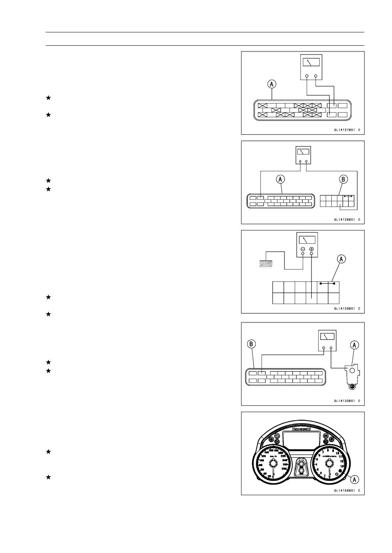
BRAKES 12-49
Anti-Lock Brake System (Equipped Models)
• Do the 2nd step test.
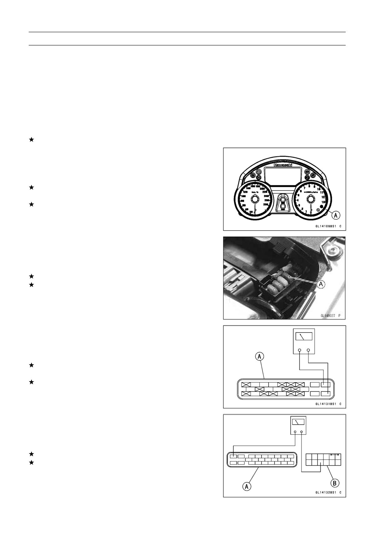
○Disconnect the ABS hydraulic unit connector [A].
○Check for continuity between the light green and
black/yellow lead terminals of the ABS hydraulic unit
connector.
If there is the continuity in the lead, replace the ABS hy-
draulic unit.
If there is not the continuity in the lead, 3rd step.
• Do the 3rd step test.
○Check for continuity between the light green lead terminal
of the main harness side connector [A] and light green
lead terminal of the fuse box [B].
If there is the continuity in the lead, replace the fuse.
If there is not the continuity in the lead, replace or repair
the main harness.
• Do the 4th step test.
○Check the battery terminal voltage between the light
green lead terminal of the fuse box [A] and ground.
Special Tool - Hand Tester 57001-1394
Battery Terminal Voltage
Standard:
Battery Voltage
If the battery terminal voltage is not within the specifica-
tion, 5th step.
If the battery terminal voltage correct, 6th step.
• Do the 5th step test.
○Check for continuity between the positive cable [A] of the
battery and light green lead terminal of the main harness
side connector [B].
If there is the continuity in the lead, 4th step.
If there is not the continuity in the lead, replace or repair
the main harness.
• Do the 6th step test.
○Recheck the service code indication; erase the service
code, perform the pre-diagnosis inspection 1 and 2, and
retrieve the service code.
If the ABS indicator light (LED) [A] lit, faulty ABS solenoid
valve relay in the ABS hydraulic unit. Replace the ABS
hydraulic unit.
If the ABS indicator light (LED) unlit, ABS system is nor-
mal (service code is not stored; temporary failure.).
12-50 BRAKES
Anti-Lock Brake System (Equipped Models)
Front, Rear Wheel Rotation Difference Abnormal
(Service Code 25)
• Do the 1st step test.
○Check the following and correct the faulty part.
Incorrect the tire pressure.
Tires not recommended for the motorcycle were installed
(incorrect tire size).
Deformation of the wheel or tire.
Sensor rotor for missing teeth and clogging with foreign
matter.
If the all parts correct, 2nd step.
• Do the 2nd step test.
○Recheck the service code indication; erase the service
code, perform the pre-diagnosis inspection 1 and 2, and
retrieve the service code.
If the ABS indicator light (LED) [A] lit, faulty ECU in the
ABS hydraulic unit. Replace the ABS hydraulic unit.
If the ABS indicator light (LED) unlit, ABS system is nor-
mal (service code is not stored; temporary failure.).
ABS Pump Motor Relay Inspection (Service Code
35)
• Do the 1st step test.
○Check the ABS pump motor relay fuse (30 A) [A].
If the fuse blown, 2nd step.
If the fuse correct, 4th step.
• Do the 2nd step test.
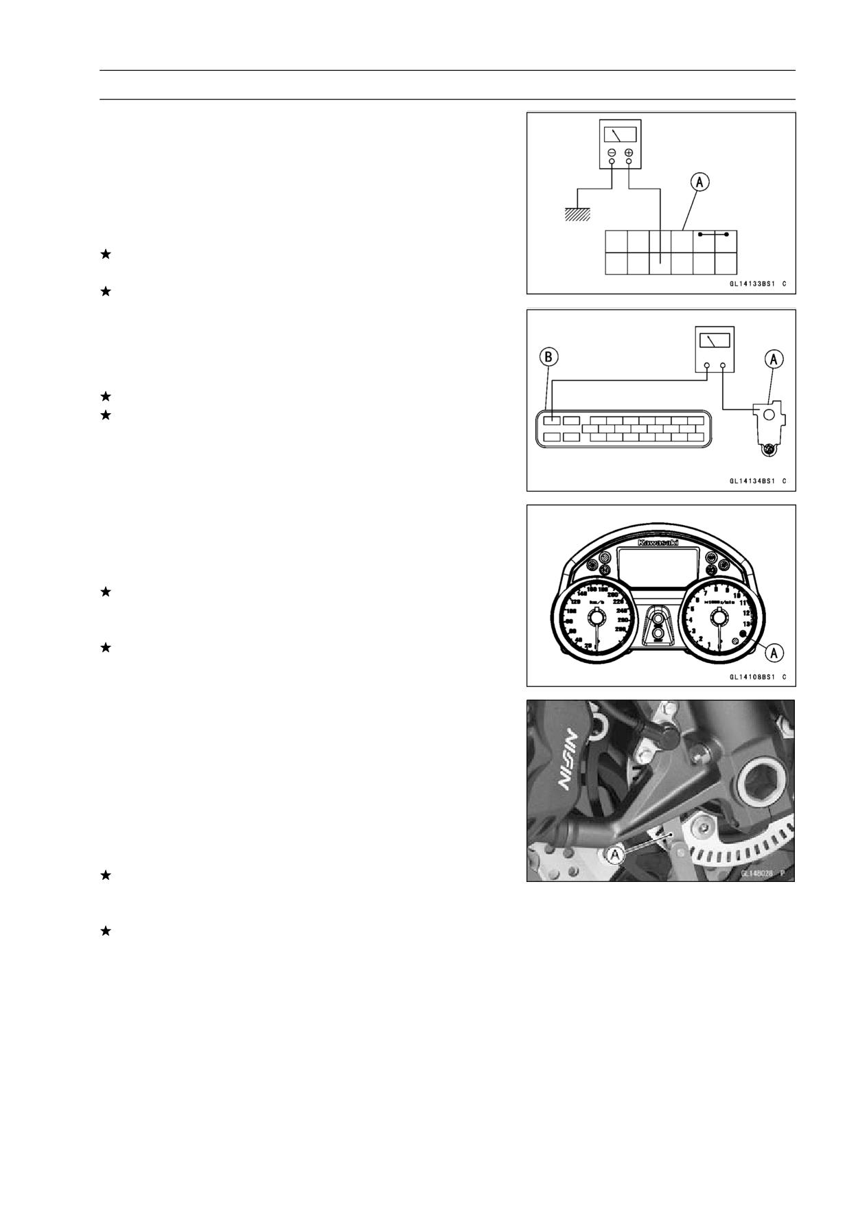
○Disconnect the ABS hydraulic unit connector.
○Check for continuity between the red and light blue lead
terminals of the ABS hydraulic unit connector [A].
If there is the continuity in the lead, replace the ABS hy-
draulic unit.
If there is not the continuity in the lead, 3rd step.
• Do the 3rd step test.
○Check for continuity between the red lead terminal of the
main harness side connector [A] and red lead terminal of
the fuse box [B].
If there is the continuity in the lead, replace the fuse.
If there is not the continuity in the lead, replace or repair
the main harness.
BRAKES 12-51
Anti-Lock Brake System (Equipped Models)
• Do the 4th step test.
○Check the battery terminal voltage between the red lead
terminal of the fuse box [A] and ground.
Special Tool - Hand Tester: 57001-1394
Battery Terminal Voltage
Standard:
Battery Voltage
If the battery terminal voltage is not within the specifica-
tion, 5th step.
If the battery terminal voltage correct, 6th step.
• Do the 5th step test.
○Check for continuity between the positive cable [A] of the
battery and red lead terminal of the main harness side
connector [B].
If there is the continuity in the lead, 4th step.
If there is not the continuity in the lead, replace or repair
the main harness.
• Do the 6th step test.
○Recheck the service code indication; erase the service
code, perform the pre-diagnosis inspection 1 and 2, and
retrieve the service code.
If the ABS indicator light (LED) [A] lit, faulty ABS pump
motor relay in the ABS hydraulic unit. Replace the ABS
hydraulic unit.
If the ABS indicator light (LED) unlit, ABS system is nor-
mal (service code is not stored; temporary failure.).
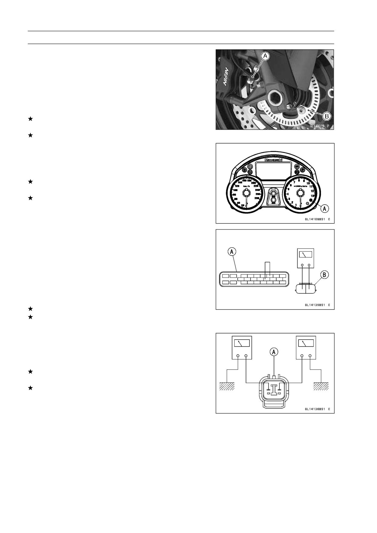
Front Wheel Rotation Sensor Signal Abnormal
(Service Code 42)
• Do the 1st step test.
○Measure the air gap between the front wheel rotation sen-
sor and sensor rotor.
Thickness Gauge [A]
Air Gap
Standard:
0.7 ∼ 0.9 mm (0.028 ∼ 0.035 in.)
If the measurement is over standard, check each part
for deformation and looseness and correct accordingly.
Recheck the air gap.
If the measurement is correct, 2nd step.
12-52 BRAKES
Anti-Lock Brake System (Equipped Models)
• Do the 2nd step test.
○Check that there is iron or other magnetic deposits be-
tween the sensor [A] and sensor rotor [B], and the sensor
rotor slots for obstructions.
○Check the installation condition of the sensor for loose-
ness.
○Check the sensor and sensor rotor tip for deformation or
damage (e.g., chipped sensor rotor teeth).
If the sensor and sensor rotor in bad condition, remove the
any deposits. Install the properly or replace faulty part.
If the all correct, 3rd step.
• Do the 3rd step test.
○Recheck the service code indication; erase the service
code, perform the pre-diagnosis inspection 1 and 2, and
retrieve the service code.
If the ABS indicator light (LED) [A] lit, faulty ECU in the
ABS hydraulic unit. Replace the ABS hydraulic unit.
If the ABS indicator light (LED) unlit, ABS system is nor-
mal (service code is not stored; temporary failure.).
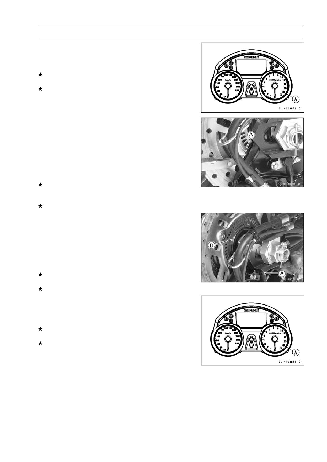
Front Wheel Rotation Sensor Wiring Inspection
(Service Code 43)
• Do the 1st step test.
○Disconnect the ABS hydraulic unit connector and front
wheel rotation sensor connector.
○Short the brown and green lead terminals of the main har-
ness side connector [A] with a jumper lead, and check for
continuity between the brown and green lead terminals of
the main harness side connector [B].
If there is the continuity in the lead, 2nd step.
If there is not the continuity in the lead, replace or repair
the main harness.
• Do the 2nd step test.
○Check for continuity between the black lead terminal of
the sensor connector [A] and ground, and white lead ter-
minal of the sensor connector and ground.
If there is the continuity in the lead, replace the front wheel
rotation sensor.
If there is not the continuity in the lead, 3rd step.
BRAKES 12-53
Anti-Lock Brake System (Equipped Models)
• Do the 3rd step test.
○Recheck the service code indication; erase the service
code, perform the pre-diagnosis inspection 1 and 2, and
retrieve the service code.
If the ABS indicator light (LED) [A] lit, faulty ECU in the
ABS hydraulic unit. Replace the ABS hydraulic unit.
If the ABS indicator light (LED) unlit, ABS system is nor-
mal (service code is not stored; temporary failure.).
Rear Wheel Rotation Sensor Signal Abnormal
(Service Code 44)
• Do the 1st step test.
○Measure the air gap between the rear wheel rotation sen-
sor and sensor rotor.
Thickness Gauge [A]
Air Gap
Standard:
0.7 ∼ 0.9 mm (0.028 ∼ 0.035 in.)
If the measurement is over standard, check each part
for deformation and looseness and correct accordingly.
Recheck the air gap.
If the measurement is correct, 2nd step.
• Do the 2nd step test.
○Check that there is iron or other magnetic deposits be-
tween the sensor [A] and sensor rotor [B], and the sensor
rotor slots for obstructions.
○Check the installation condition of the sensor for loose-
ness.
○Check the sensor and sensor rotor tip for deformation or
damage (e.g., chipped sensor rotor teeth).
If the sensor and sensor rotor in bad condition, remove the
any deposits. Install the properly or replace faulty part.
If the all correct, 3rd step.
• Do the 3rd step test.
○Recheck the service code indication; erase the service
code, perform the pre-diagnosis inspection 1 and 2, and
retrieve the service code.
If the ABS indicator light (LED) [A] lit, faulty ECU in the
ABS hydraulic unit. Replace the ABS hydraulic unit.
If the ABS indicator light (LED) unlit, ABS system is nor-
mal (service code is not stored; temporary failure.).
12-54 BRAKES
Anti-Lock Brake System (Equipped Models)
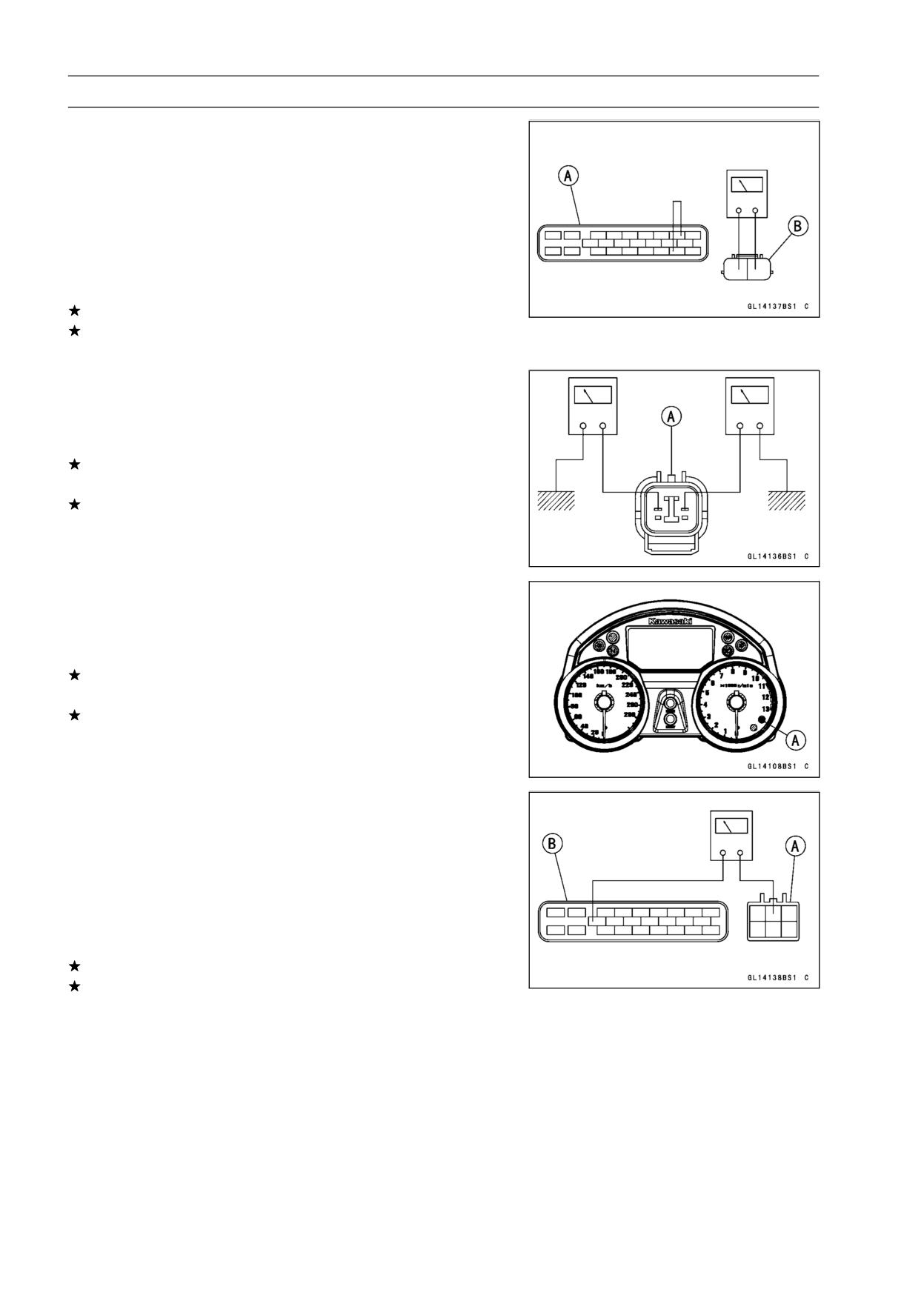
Rear Wheel Rotation Sensor Wiring Inspection
(Service Code 45)
• Do the 1st step test.
○Disconnect the ABS hydraulic unit connector and rear
wheel rotation sensor connector.
○Short the black and white/red lead terminals of the main
harness side connector [A] with a jumper lead, and check
for continuity between the black and white/red lead termi-
nals of the main harness side connector [B].
If there is the continuity in the lead, 2nd step.
If there is not the continuity in the lead, replace or repair
the main harness.
• Do the 2nd step test.
○Check for continuity between the black lead terminal of
the sensor connector [A] and ground, and white lead ter-
minal of the sensor connector and ground.
If there is the continuity in the lead, replace the rear wheel
rotation sensor.
If there is not the continuity in the lead, 3rd step.
• Do the 3rd step test.
○Recheck the service code indication; erase the service
code, perform the pre-diagnosis inspection 1 and 2, and
retrieve the service code.
If the ABS indicator light (LED) [A] lit, faulty ECU in the
ABS hydraulic unit. Replace the ABS hydraulic unit.
If the ABS indicator light (LED) unlit, ABS system is nor-
mal (service code is not stored; temporary failure.).
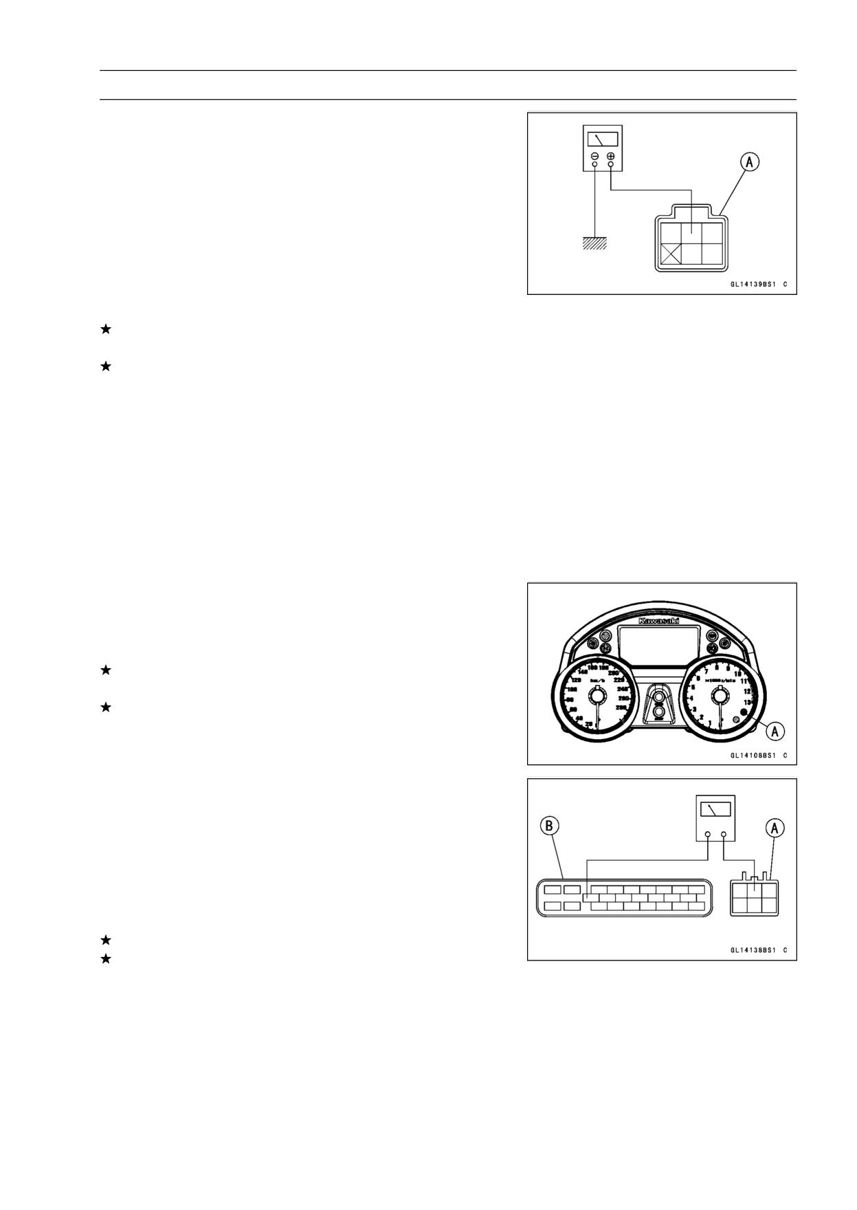
Power Supply Voltage Abnormal (Under-Voltage)
(Service Code 52)
• Do the 1st step test.
○Disconnect the ignition switch connector and ABS hy-
draulic unit connector.
○Check for continuity between the brown lead terminal of
the main harness side connector [A] and yellow lead ter-
minal of the main harness side connector [B].
If there is the continuity in the lead, 2nd step.
If there is not the continuity in the lead, inspect the ABS
ECU fuse (10 A) (see Fuse Inspection in the Electrical
System chapter) and replace or repair the main harness.
BRAKES 12-55
Anti-Lock Brake System (Equipped Models)
• Do the 2nd step test.
○Connect the ignition switch connector and ABS hydraulic
unit connector.
○Check the battery terminal voltage, connect the hand
tester to the brown terminal of ignition switch connector
[A] and ground.
Special Tool - Hand Tester: 57001-1394
○Turn the ignition switch ON.
Battery Terminal Voltage
Standard:
10 V or more
If the battery terminal voltage is not within the specifica-
tion, 3rd step.
If the battery terminal voltage correct, 4th step.
• Do the 3rd step test.
○Inspect the following parts.
Battery (see Charging Condition Inspection in the Elec-
trical System chapter)
Ignition Switch (see Switch Inspection in the Electrical
System chapter)
Main Harness (see Wiring Inspection in the Electrical
System chapter)
Main Fuse 30 A (see Fuse Inspection in the Electrical
System chapter)
• Do the 4th step test.
○Recheck the service code indication; erase the service
code, perform the pre-diagnosis inspection 1 and 2, and
retrieve the service code.
If the ABS indicator light (LED) [A] lit, faulty ECU in the
ABS hydraulic unit. Replace the ABS hydraulic unit.
If the ABS indicator light (LED) unlit, ABS system is nor-
mal (service code is not stored; temporary failure.).
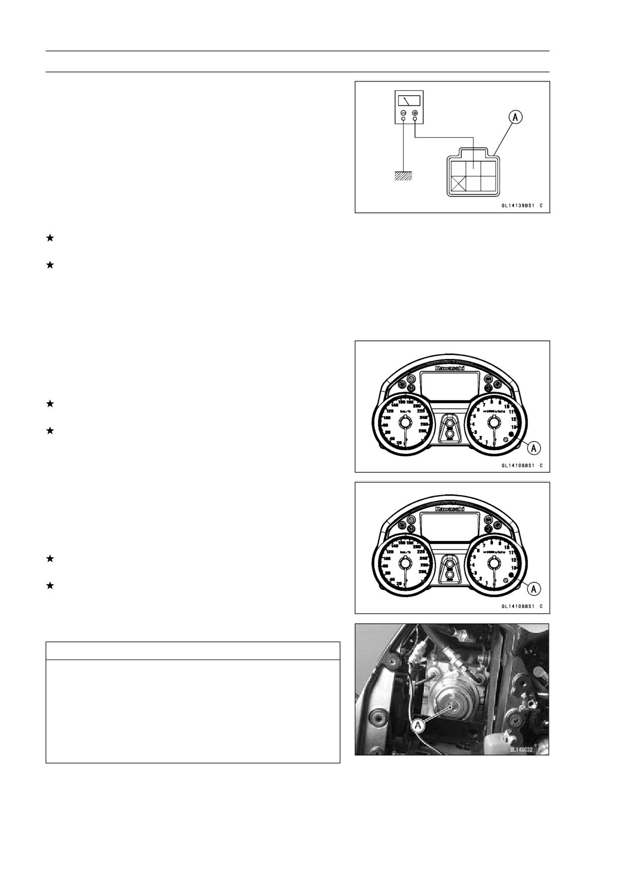
Power Supply Voltage Abnormal (Over-Voltage)
(Service Code 53)
• Do the 1st step test.
○Disconnect the ignition switch connector and ABS hy-
draulic unit connector.
○Check for continuity between the brown lead terminal of
the main harness side connector [A] and yellow lead ter-
minal of the main harness side connector [B].
If there is the continuity in the lead, 2nd step.
If there is not the continuity in the lead, inspect the ABS
ECU fuse (10 A) (see Fuse Inspection in the Electrical
System chapter) and replace or repair the main harness.
12-56 BRAKES
Anti-Lock Brake System (Equipped Models)
• Do the 2nd step test.
○Connect the ignition switch connector and ABS hydraulic
unit connector.
○Check the battery terminal voltage, connect the hand
tester to the brown terminal of ignition switch connector
[A] and ground.
Special Tool - Hand Tester: 57001-1394
○Turn the ignition switch ON.
Battery Terminal Voltage
Standard:
16 V or less
If the battery terminal voltage is not within the specifica-
tion, 3rd step.
If the battery terminal voltage correct, 4th step.
• Do the 3rd step test.
○Check the battery condition and regulator/rectifier (see
Charging Condition Inspection, Regulator/Rectifier In-
spection in the Electrical System chapter).
• Do the 4th step test.
○Recheck the service code indication; erase the service
code, perform the pre-diagnosis inspection 1 and 2, and
retrieve the service code.
If the ABS indicator light (LED) [A] lit, faulty ECU in the
ABS hydraulic unit. Replace the ABS hydraulic unit.
If the ABS indicator light (LED) unlit, ABS system is nor-
mal (service code is not stored; temporary failure.).
ECU Inspection (Service Code 55)
• Do the 1st step test.
○Recheck the service code indication; erase the service
code, perform the pre-diagnosis inspection 1 and 2, and
retrieve the service code.
If the ABS indicator light (LED) [A] lit, faulty ECU in the
ABS hydraulic unit. Replace the ABS hydraulic unit.
If the ABS indicator light (LED) unlit, ABS system is nor-
mal (service code is not stored; temporary failure.).
ABS Hydraulic Unit Removal
CAUTION
The ABS hydraulic unit [A] has been adjusted
and set with precision at the factory. Therefore, it
should be handled carefully, never struck sharply,
as with a hammer, or allowed to fall on a hard
surface.
Be careful not to get water or mud on the ABS hy-
draulic unit.
• Drain the brake fluid from the front and rear brake lines.
○Drain the brake fluid through the bleed valve by pumping
the brake lever and pedal.
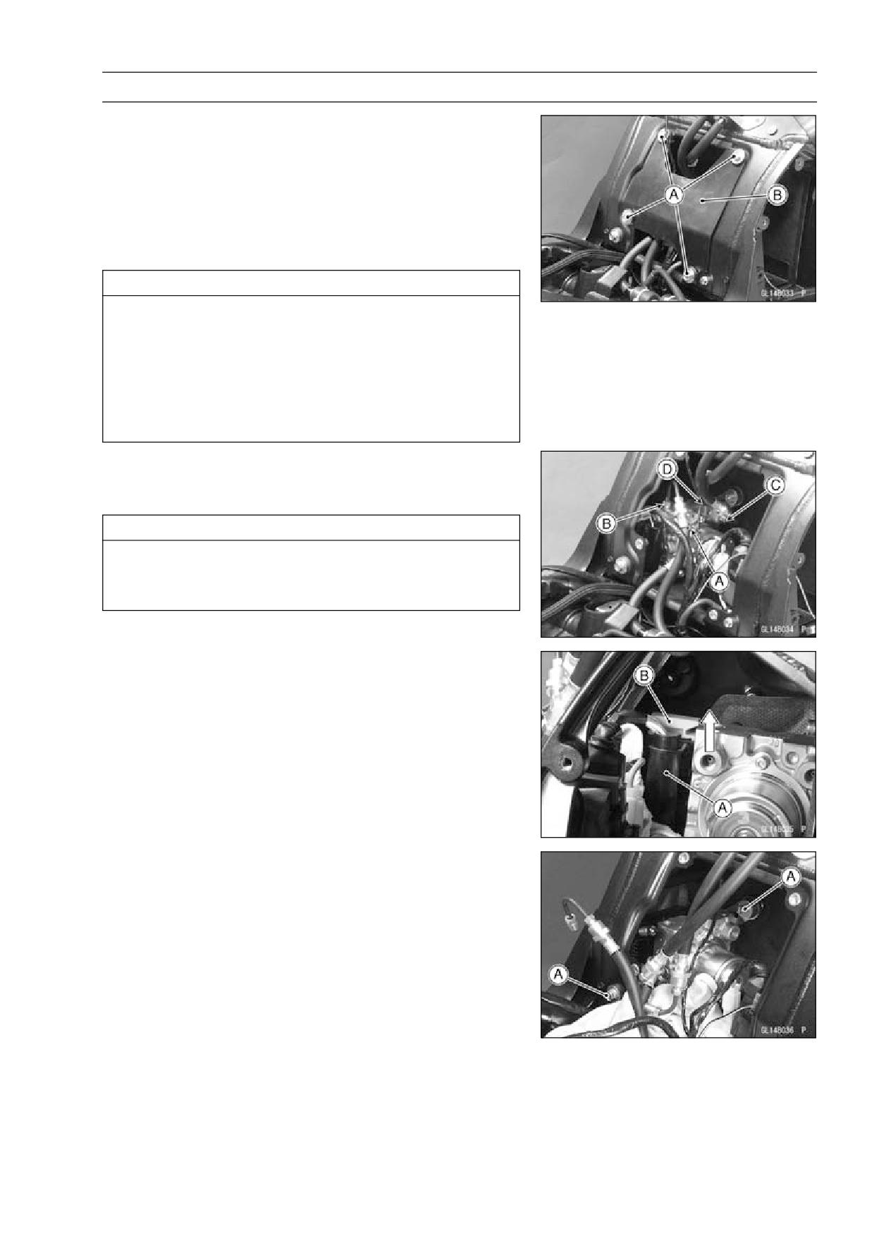
BRAKES 12-57
Anti-Lock Brake System (Equipped Models)
• Remove:
Fuel Tank (see Fuel Tank Removal in the Fuel System
(DFI) chapter)
Battery (see Battery Removal in the Electrical System
chapter)
Bolts [A]
Cover [B]
• Clean the ABS hydraulic unit.
CAUTION
Clean all fittings on the ABS hydraulic unit and the
rear master cylinder because dirt around the banjo
bolts could contaminate the brake fluid in the line
during removal/installation.
Spread out a shop towel around the ABS hydraulic
unit before removing the brake line so that brake
fluid does not leak on the parts.
• Remove the brake pipe joint nuts [A] [B] [C] [D].
• Tape the brake line opening to prevent brake fluid leakage
or contamination by foreign matter.
CAUTION
Brake fluid quickly ruins painted plastic surfaces;
any spilled fluid should be completely washed away
immediately.
• Disconnect the connector [A].
○Unlock the joint lock [B] as shown in the figure.
• Remove the bolts [A].
• Remove the ABS hydraulic unit with bracket.
12-58 BRAKES
Anti-Lock Brake System (Equipped Models)
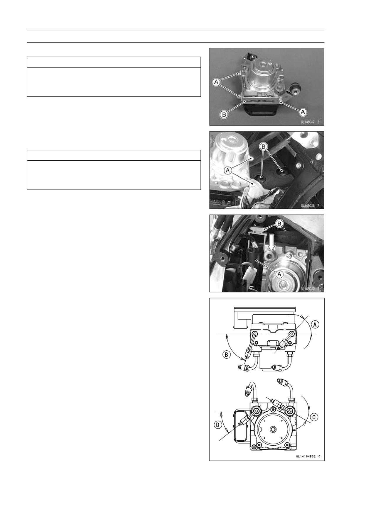
• Remove the bolts [A] and bracket [B].
CAUTION
The ABS hydraulic unit has been adjusted and set
with precision at the factory. Do not try to disas-
semble and repair the ABS hydraulic unit.
ABS Hydraulic Unit Installation
• Install the ABS hydraulic unit to the bracket.
CAUTION
Brake fluid quickly ruins painted plastic surfaces;
any spilled fluid should be completely washed away
immediately.
• Insert the bolts [A] into the grommets [B].
• Route the lead correctly, and connector [A] securely.
○Lock the joint lock [B] as shown in the figure.
• Install the brake pipes correctly as shown in the figure.
48° [A]
71° [B]
30° [C]
38.5° [D]
• Tighten the joint nuts.
Torque - Brake Pipe Joint Nuts: 18 N·m (1.8 kgf·m, 13 ft·lb)
• Bleed the brake line (see Brake Line Bleeding).
• Check the brake for good braking power, no brake drag,
and no fluid leakage.
• Install the removed parts (see appropriate chapters).
BRAKES 12-59
Anti-Lock Brake System (Equipped Models)
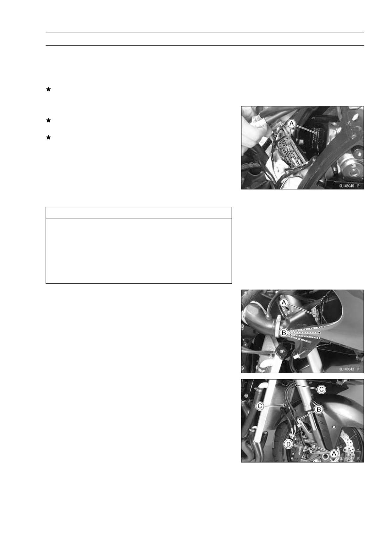
ABS Hydraulic Unit Inspection
• Remove the ABS hydraulic unit (see ABS Hydraulic Unit
Removal).
• Visually inspect the ABS hydraulic unit.
Replace the ABS hydraulic unit if any of them are cracked,
or otherwise damaged.
• Visually inspect the connector terminals [A].
Replace the ABS hydraulic unit or main harness if either
of the terminals are cracked, bent, or otherwise damaged.
If the ABS hydraulic unit connector is clogged with mud
or dust, blow it off with compressed air.
Front Wheel Rotation Sensor Removal
CAUTION
The wheel rotation sensor should be handled care-
fully, never struck sharply, as with a hammer, or al-
lowed to fall on a hard surface since the wheel rota-
tion sensor is precision made. Be careful not to get
water or mud on the wheel rotation sensor.
Do not try to disassemble or repair the wheel rota-
tion sensor.
• Remove:
Left Middle Fairing (see Middle Fairing Removal in the
Frame chapter)
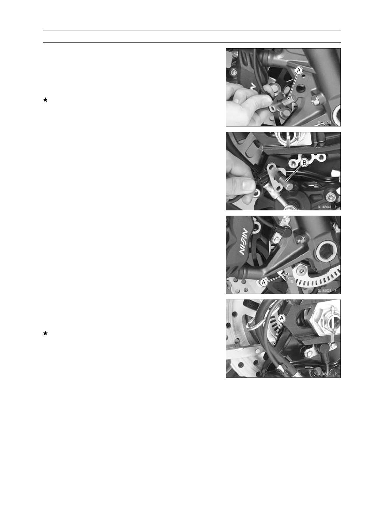
Connector [A] (Disconnect)
Clamps [B]
• Remove:
Bolts [A]
Bracket Bolt [B]
Clamps [C]
Front Wheel Rotation Sensor [D]
Front Wheel Rotation Sensor Installation
• Installation is the reverse of removal.
○Route the lead correctly (see Cable, Wire, and Hose
Routing section in the Appendix chapter).
12-60 BRAKES
Anti-Lock Brake System (Equipped Models)
Rear Wheel Rotation Sensor Removal
CAUTION
The wheel rotation sensor should be handled care-
fully, never struck sharply, as with a hammer, or al-
lowed to fall on a hard surface since the wheel rota-
tion sensor is precision made. Be careful not to get
water or mud on the wheel rotation sensor.
Do not try to disassemble or repair the wheel rota-
tion sensor.
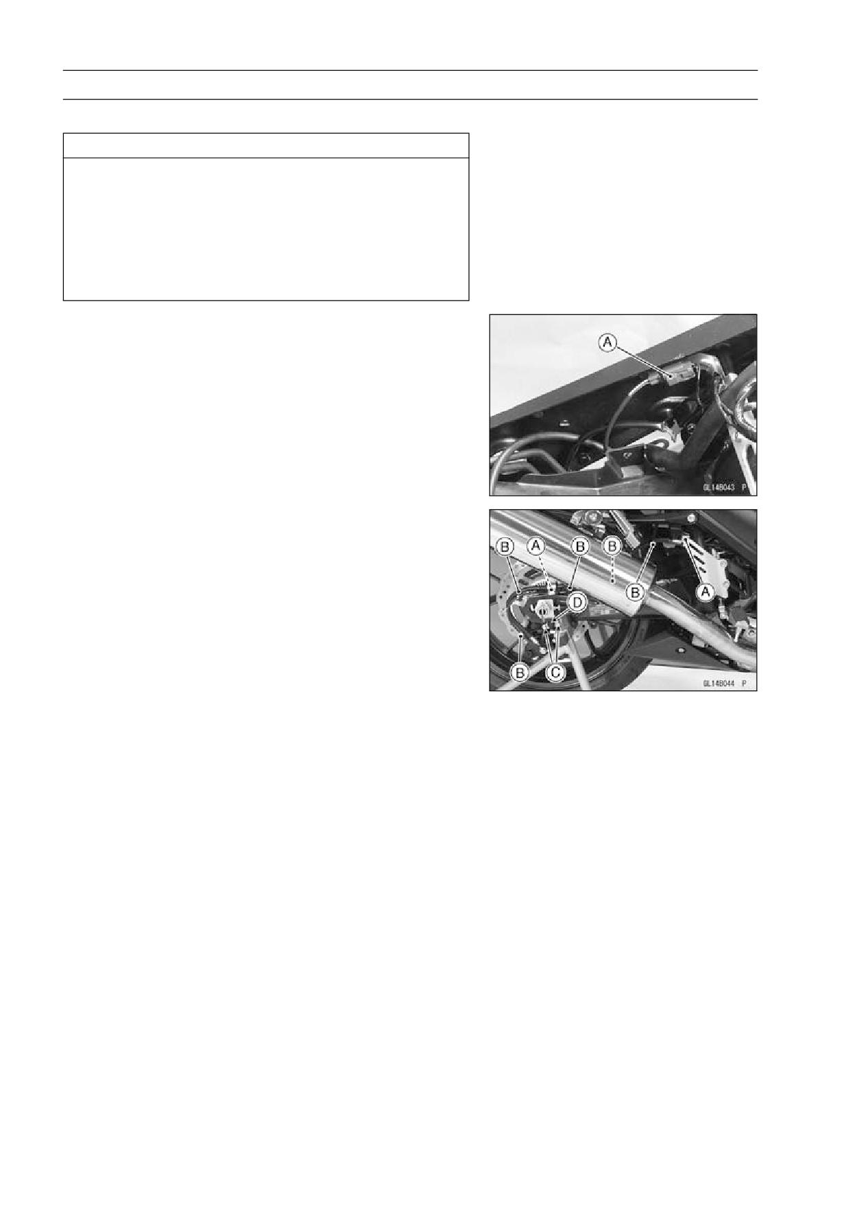
• Remove:
Fuel Tank (see Fuel Tank Removal in the Fuel System
(DFI) chapter)
Connector [A] (Disconnect)
• Clear the connector from the bracket.
• Remove:
Bracket Bolts [A]
Clamps [B]
Bolts [C]
Rear Wheel Rotation Sensor [D]
Rear Wheel Rotation Sensor Installation
• Installation is the reverse of removal.
○Route the lead correctly (see Cable, Wire, and Hose
Routing section in the Appendix chapter).
BRAKES 12-61
Anti-Lock Brake System (Equipped Models)
Wheel Rotation Sensor Inspection
• Remove the front wheel rotation sensor [A] from the front
fork.
• Remove the rear wheel rotation sensor [B] from the
caliper bracket.
• Visually inspect the wheel rotation sensors.
Replace the wheel rotation sensor if it is cracked, bent, or
otherwise damaged.
Wheel Rotation Sensor Air Gap Inspection
• Raise the front/rear wheel off the ground (see Front/Rear
Wheel Removal in the Wheels/Tires chapter).
• Measure the air gap between the sensor and sensor rotor
at several points by turning the wheel slowly.
Thickness Gauge [A]
Air Gap
Standard:
Front
0.7 ∼ 0.9 mm (0.028 ∼ 0.035 in.)
Rear
0.7 ∼ 0.9 mm (0.028 ∼ 0.035 in.)
NOTE
○The sensor air gap cannot be adjusted.
If the air gap is not within the specification, inspect the hub
bearing (see Hub Bearing Inspection in the Wheels/Tires
chapter), sensor installation condition and sensor (see
Wheel Rotation Sensor Inspection).
12-62 BRAKES
Anti-Lock Brake System (Equipped Models)
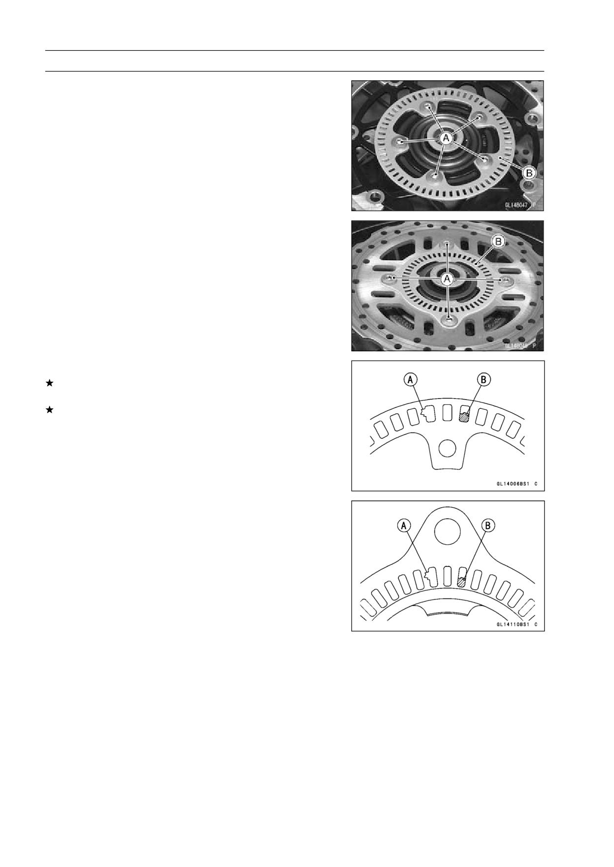
Wheel Rotation Sensor Rotor Inspection
• Remove:
Wheels (see Front/Rear Wheel Removal in the
Wheels/Tires chapter)
Brake Disc Mounting Bolts [A]
Sensor Rotor [B]
• Visually inspect the wheel rotation sensor rotor.
If the rotor is deformed or damaged (chipped teeth [A]),
replace the sensor rotor with a new one.
If there is iron or other magnetic deposits [B], remove the
deposits.
ABS Solenoid Valve Relay Fuse (20 A) Removal
• Refer to the Fuse Box Fuse Removal in the Electrical Sys-
tem chapter.
ABS Motor Relay Fuse (30 A) Removal
• Refer to the Fuse Box Fuse Removal in the Electrical Sys-
tem chapter.
ABS ECU Fuse (10 A) Removal
• Refer to the Fuse Box Fuse Removal in the Electrical Sys-
tem chapter.
BRAKES 12-63
Anti-Lock Brake System (Equipped Models)
Fuse Installation
• If a fuse fails during operation, inspect the electrical sys-
tem to determine the cause, and then replace it with a
new fuse of proper amperage (see Fuse Installation in the
Electrical System chapter).
Fuse Inspection
• Remove the fuses (see ABS Solenoid Valve Relay Fuse
(20 A) /ABS Motor Relay Fuse (30 A) Removal).
• Refer to the Fuse Inspection in the Electrical System
chapter.
SUSPENSION 13-1
Suspension
Table of Contents
Exploded View
13-2
Specifications
13-6
Special Tools
13-7
Front Fork
13-9
Rebound Damping Force Adjustment
13-9
Compression Damping Force Adjustment
13-9
Spring Preload Adjustment
13-10
Front Fork Removal (Each Fork Leg)
13-10
Front Fork Installation
13-11
Front Fork Oil Change
13-11
Front Fork Disassembly
13-16
Front Fork Assembly
13-16
Inner Tube Inspection
13-17
Dust Seal Inspection
13-18
Spring Tension
13-18
Rear Shock Absorber
13-19
Rebound Damping Force Adjustment
13-19
Compression Damping Force Adjustment
13-19
Spring Preload Adjustment
13-19
Rear Shock Absorber Removal
13-20
Rear Shock Absorber Installation
13-21
Rear Shock Absorber Inspection
13-21
Rear Shock Absorber Scrapping
13-22
Swingarm
13-23
Swingarm Removal
13-23
Swingarm Installation
13-24
13
Swingarm Bearing Removal
13-25
Swingarm Bearing Installation
13-25
Swingarm Bearing, Sleeve Inspection
13-26
Chain Guide Inspection
13-27
Tie-Rod, Rocker Arm
13-28
Tie-Rod Removal
13-28
Tie-Rod Installation
13-28
Rocker Arm Removal
13-28
Rocker Arm Installation
13-29
Tie-Rod and Rocker Arm Bearing Removal
13-29
Tie-Rod and Rocker Arm Bearing Installation
13-29
Rocker Arm/Tie-Rod Bearing, Sleeve Inspection
13-31
Rocker Arm/Tie-Rod Bearing Lubrication
13-31
13-2 SUSPENSION
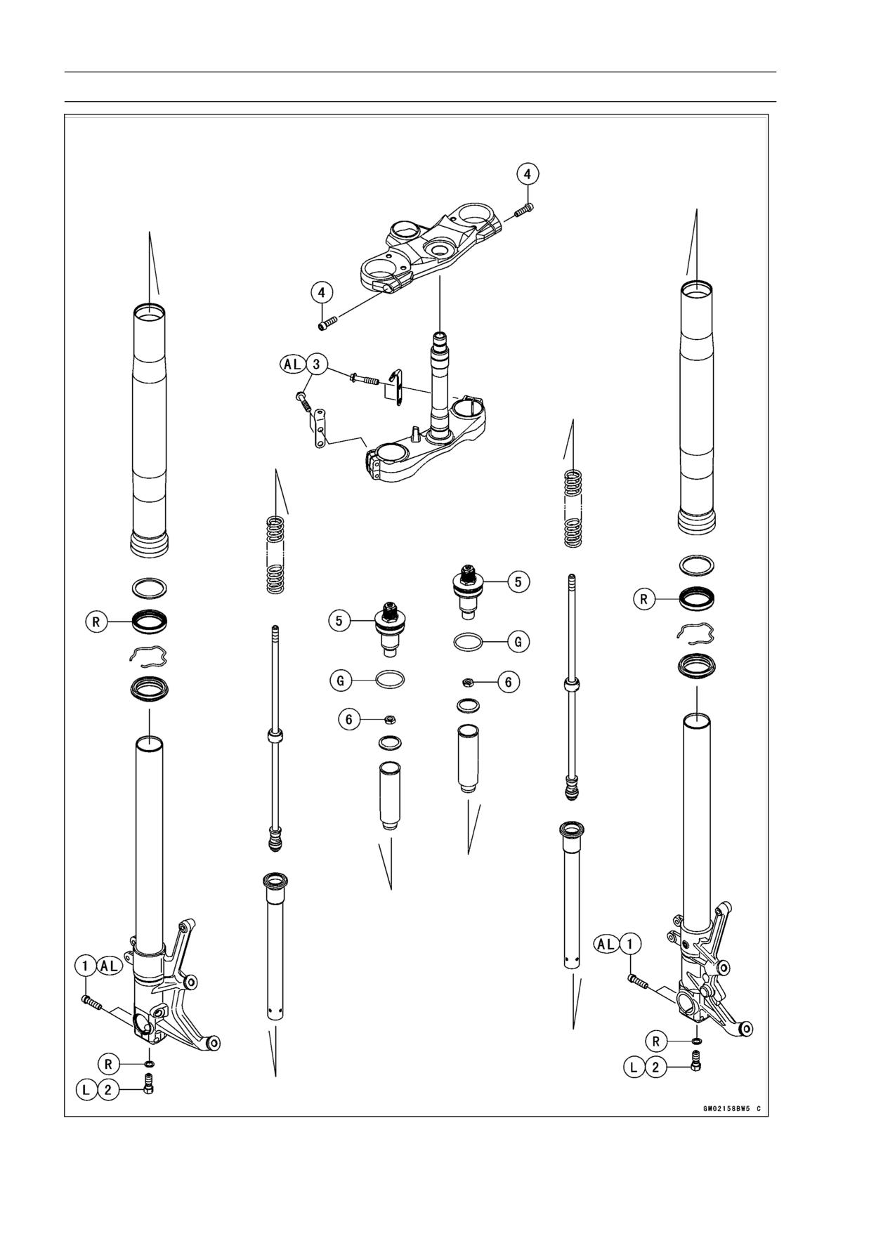
Exploded View
SUSPENSION 13-3
Exploded View
Torque
No.
Fastener
Remarks
N·m
kgf·m
ft·lb
1
Front Axle Clamp Bolts
20
2.0
15
AL
2
Front Fork Bottom Allen Bolts
23
2.3
17
L
3
Front Fork Clamp Bolts (Lower)
30
3.1
22
AL
4
Front Fork Clamp Bolts (Upper)
20
2.0
15
5
Front Fork Top Plugs
22
2.2
16
6
Piston Rod Nuts
28
2.9
21
AL: Tighten the two clamp bolts alternately two times to ensure even tightening torque.
G: Apply grease.
L: Apply a non-permanent locking agent.
R: Replacement Parts
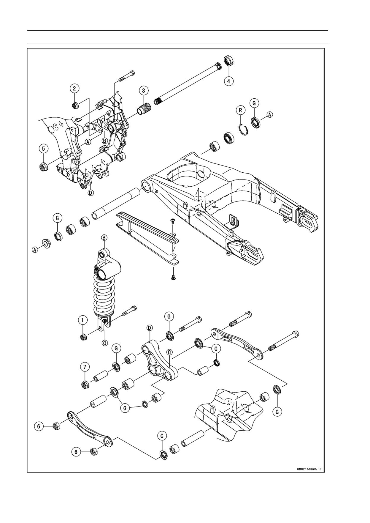
13-4 SUSPENSION
Exploded View
SUSPENSION 13-5
Exploded View
Torque
No.
Fastener
Remarks
N·m
kgf·m
ft·lb
1
Rear Shock Absorber Nut (Lower)
34
3.5
25
2
Rear Shock Absorber Nut (Upper)
34
3.5
25
3
Swingarm Pivot Adjusting Collar
20
2.0
15
4
Swingarm Pivot Adjusting Collar Locknut
98
10.0
72
5
Swingarm Pivot Shaft Nut
108
11.0
80
6
Tie-Rod Nuts
59
6.0
44
7
Uni-Trak Rocker Arm Nut
34
3.5
25
G: Apply grease.
R: Replacement Parts
13-6 SUSPENSION
Specifications
Item
Standard
Front Fork (Per One Unit)
Fork Inner Tube Diameter
43 mm (1.7 in.)
Air Pressure
Atmospheric pressure (non-adjustable)
Rebound Damper Setting
5th click from the 1st click of the fully clockwise position
(Usable range: 0 ←→ 11 clicks)
Compression Damper Setting
10th click from the 1st click of the fully clockwise position
(Usable range: 0 ←→ 13 clicks)
Fork Spring Preload Setting
Adjuster protrusion is 15 mm (0.59 in.)
(Usable range: 4 ∼ 19 mm) (0.16 ∼ 0.75 in.)
Fork Oil:
Viscosity
KAYABA 01 (KHL15-10) or equivalent SAE 5W
Amount
Approx. 480 mL (16.2 US oz.) (when changing oil)
563 ±4 mL (19.0 ±0.14 US oz.) (after disassembly and completely
dry)
Fork Oil Level
88 ±2 mm (3.46 ±0.08 in.) (fully compressed, without fork spring,
below from inner tube top)
Fork Spring Free Length
257 mm (10.12 in.) (Service Limit: 252 mm (9.92 in.))
Rear Shock Absorber
Rebound Damper Set
1 2/4 turns out from the fully clockwise position
(Usable range: 0 ←→ 2 2/4 turns out)
Compression Damper Set
2 1/4 turns out from the fully clockwise position
(Usable range: 0 ←→ 4 turns out)
Spring Preload Setting
Position:
Standard
Spring length: 175.5 mm (6.9 in.)
Usable Range
Spring length: 175.5 ∼ 191.5 mm (6.909 ∼ 7.539 in.)
(weaker to stronger)
Gas Pressure
1 080 kPa (11.0 kgf/cm², 156 psi, non-adjustable)
SUSPENSION 13-7
Special Tools
Inside Circlip Pliers:
Fork Piston Rod Puller, M12 × 1.25:
57001-143
57001-1289
Oil Seal & Bearing Remover:
Fork Oil Level Gauge:
57001-1058
57001-1290
Bearing Driver Set:
Bearing Remover Head,
20 ×
22:
57001-1129
57001-1293
Jack:
Bearing Remover Shaft,
13:
57001-1238
57001-1377
Fork Cylinder Holder:
Hook Wrench T=3.2 R37:
57001-1287
57001-1522
13-8 SUSPENSION
Special Tools
Fork Oil Seal Driver,
43:
Needle Bearing Driver,
17/
18:
57001-1530
57001-1609
Fork Spring Compressor:
Stem Bearing Driver,
28:
57001-1540
57001-1610
Fork Spring Compressor:
Spacer,
18:
57001-1587
57001-1636
Swingarm Pivot Nut Wrench:
Spacer
28:
57001-1597
57001-1663
Jack Attachment:
Needle Bearing Driver,
20 & Spacer,
28:
57001-1608
57001-1678
SUSPENSION 13-9
Front Fork
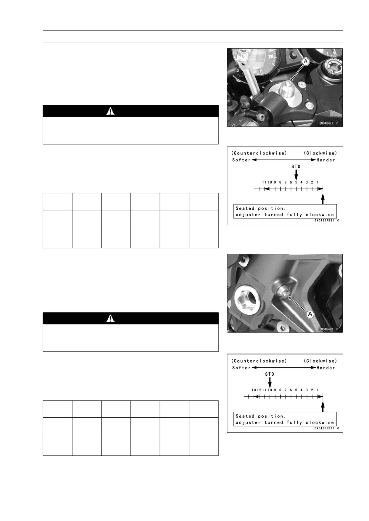
Rebound Damping Force Adjustment
• To adjust the rebound damping force, turn the rebound
damping adjuster [A] until you feel a click.
○The standard adjuster setting for the average-build rider
of 68 kg (150 lb) with no passenger and no accessories
is the 5th click from the 1st click of the fully clockwise
position.
WARNING
If both adjusters are not adjusted equally, handling
may be impaired and a hazardous condition may
result.
○The damping force can be left soft for average riding. But
it should be adjusted harder for high speed riding or riding
with a passenger. If the damping feels too soft or too stiff,
adjust it in accordance with the following table.
Rebound Damping Force Adjustment
Adjuster
Damping
Setting
Load
Road
Speed
Position
Force
11
Weak
Soft
Light
Good
Low
↑
↑
↑
↑
↑
↑
↓
↓
↓
↓
↓
↓
0
Strong
Hard
Heavy
Bad
High
Compression Damping Force Adjustment
• To adjust the compression damping force, turn the com-
pression damping adjuster [A] until you feel a click.
○The standard adjuster setting for the average-build rider
of 68 kg (150 lb) with no passenger and no accessories
is the 10th click from the 1st click of the fully clockwise
position.
WARNING
If both adjusters are not adjusted equally, handling
may be impaired and a hazardous condition may
result.
○The damping force can be left soft for average riding. But
it should be adjusted harder for high speed riding or riding
with a passenger. If the damping feels too soft or too stiff,
adjust it in accordance with the following table.
Compression Damping Force Adjustment
Adjuster
Damping
Setting
Load
Road
Speed
Position
Force
13
Weak
Soft
Light
Good
Low
↑
↑
↑
↑
↑
↑
↓
↓
↓
↓
↓
↓
0
Strong
Hard
Heavy
Bad
High
13-10 SUSPENSION
Front Fork
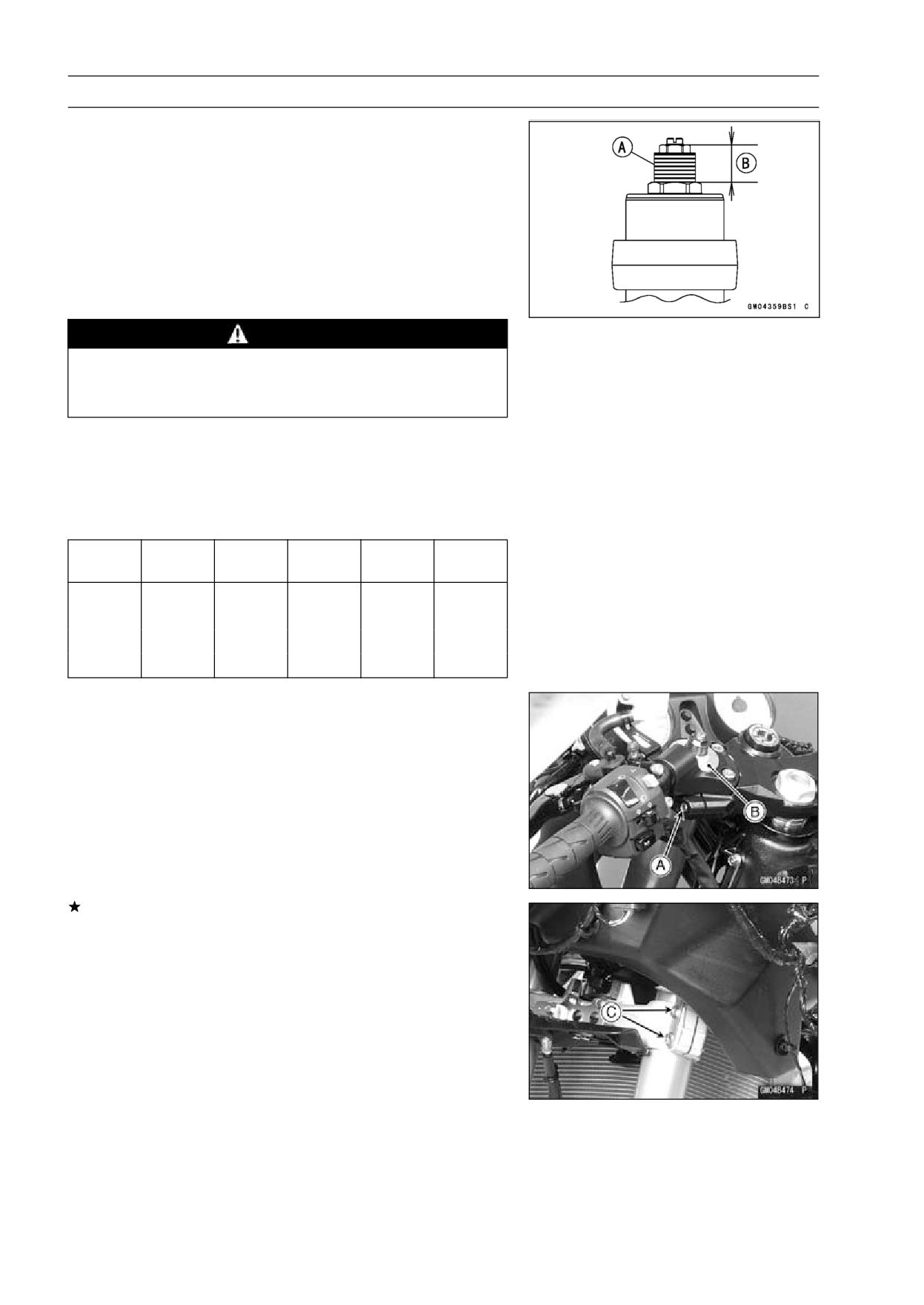
Spring Preload Adjustment
• Turn the spring preload adjuster [A] to change spring
preload setting.
○The standard adjuster setting for the average-build rider
of 68 kg (150 lb) with no passenger and no accessories is
the 15 mm (0.59 in.) [B] from top as shown in the figure.
Adjuster Protrusion (from top)
Standard:
15 mm (0.59 in.)
Usable Range:
4 ∼ 19 mm (0.16 ∼ 0.75 in.)
WARNING
If both adjusters are not adjusted equally, handling
may be impaired and a hazardous condition may
result.
○The spring preload can be left soft for average riding. But
it should be adjusted harder for high speed riding or riding
with a passenger. If the spring action feels too soft or too
stiff, adjust it in accordance with the following table.
Spring Action
Adjuster
Damping
Setting
Load
Road
Speed
Position
Force
19 mm
Weak
Soft
Light
Good
Low
↑
↑
↑
↑
↑
↑
↓
↓
↓
↓
↓
↓
4 mm
Strong
Hard
Heavy
Bad
High
Front Fork Removal (Each Fork Leg)
• Remove:
Middle Fairings (see Middle Fairing Removal in the
Frame chapter)
Inner Covers (see Inner Cover Removal in the Frame
chapter)
Front Wheel (see Front Wheel Removal in the
Wheels/Tires chapter)
Front Fender (see Front Fender Removal in the Frame
chapter)
Loosen the upper fork clamp bolt [A] and fork top plug [B]
beforehand if the fork leg is to be disassembled.
NOTE
○Loosen the top plug after loosening the upper fork
clamp bolt.
• Loosen the upper fork clamp bolt and lower fork clamp
bolts [C].
• With a twisting motion, work the fork leg down and out.
SUSPENSION 13-11
Front Fork
Front Fork Installation
• Install the fork so that the top end [A] of the outer tube as
shown in the figure.
21.5 mm (0.85 in.) [B]
• Tighten the lower fork clamp bolts and fork top plug.
Torque - Front Fork Clamp Bolts (Lower):
30 N·m (3.1
kgf·m, 22 ft·lb)
Front Fork Top Plug: 22 N·m (2.2 kgf·m, 16 ft·lb)
• Tighten the upper fork clamp bolt.
Torque - Front Fork Clamp Bolt (Upper): 20 N·m (2.0 kgf·m,
15 ft·lb)
NOTE
○Tighten the two clamp bolts alternately two times to en-
sure even tightening torque.
○Tighten the top plug before tightening the upper fork
clamp bolt.
• Install the removed parts (see appropriate chapters).
• Adjust the spring preload and the damping force.
Front Fork Oil Change
• Remove the front fork (see Front Fork Removal).
• Hold the inner tube lower end in a vise.
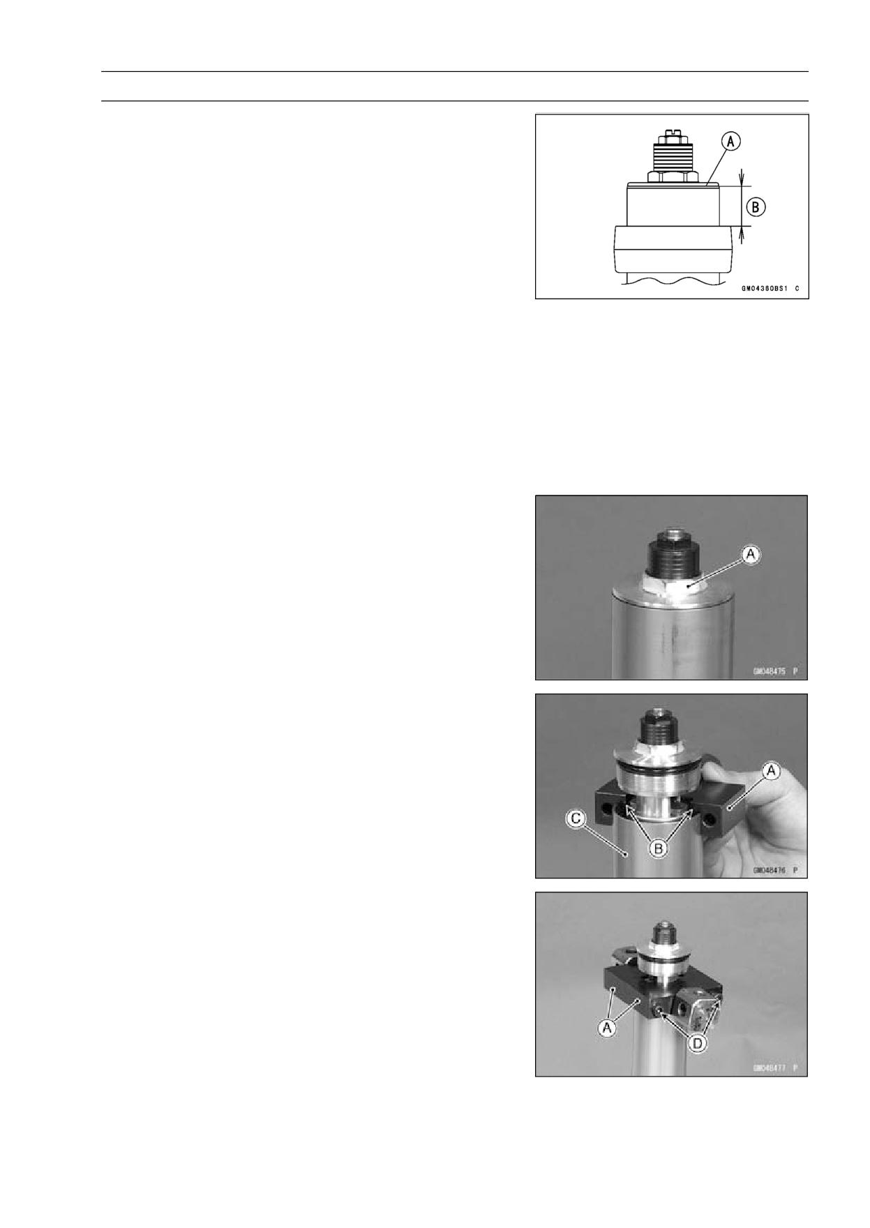
• Unscrew the top plug [A] out of the outer tube.
• Install the clamps [A] as shown in the figure.
NOTE
○Set the clamps so that the cutout [B] of the upper side
does not touch the tongue shape of stopper, pull up the
outer tube [C] to hold it by the clamps, and then tighten
the two bolts [D]. The outer tube is used as a guide.
Special Tools - Fork Spring Compressor: 57001-1540
Fork Spring Compressor: 57001-1587
13-12 SUSPENSION
Front Fork
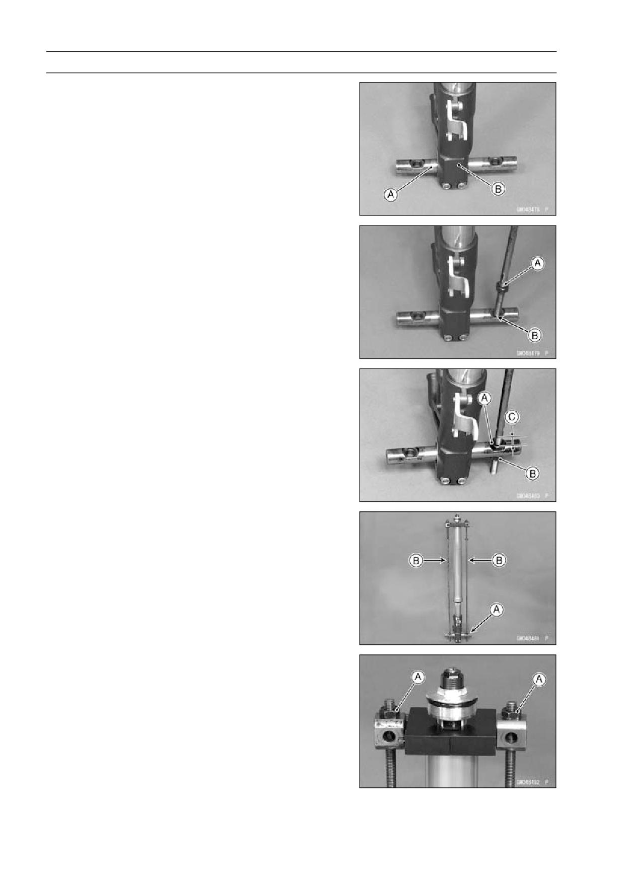
• Insert the holder bar [A] into the axle hole of the front fork
[B].
• Insert the compression shaft and install the nut.
• Insert the lower end of the compression shaft [A] into the
hole [B] of the holder bar.
• Screw the adjust nut [A] onto the compression shaft as
shown in the figure.
• Screw the locknut [B].
About 20 mm (0.79 in.) [C]
• Set the other side compression shaft same process.
• Set the holder bar [A] and compression shafts [B].
• Screw in nuts [A] come out the piston rod nut.
SUSPENSION 13-13
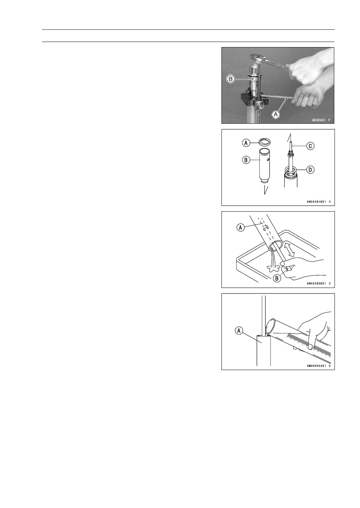
Front Fork
• Holding the piston rod nut with a wrench [A], remove the
top plug [B] from the piston rod.
• Remove:
Washer [A]
Collar [B]
Rebound Damping Adjuster Rod [C]
Fork Spring [D]
• Drain the fork oil into a suitable container.
○Pump the piston rod [A] up and down at least ten times to
expel the oil from the fork.
Special Tool - Fork Piston Rod Puller, M12 × 1.25 [B]:
57001-1289
• Hold the fork tube upright, press the inner tube [A] and
the piston rod all the way down.
• Pour in the type and amount of fork oil specified.
Fork Oil
Viscosity:
KAYABA 01 (KHL15-10) or equivalent SAE
5W
Amount (per side):
When changing oil: Approx. 480 mL (16.2 US oz.)
After disassembly and completely dry:
563 ±4 mL (19.0 ±0.14 US oz.)
13-14 SUSPENSION
Front Fork
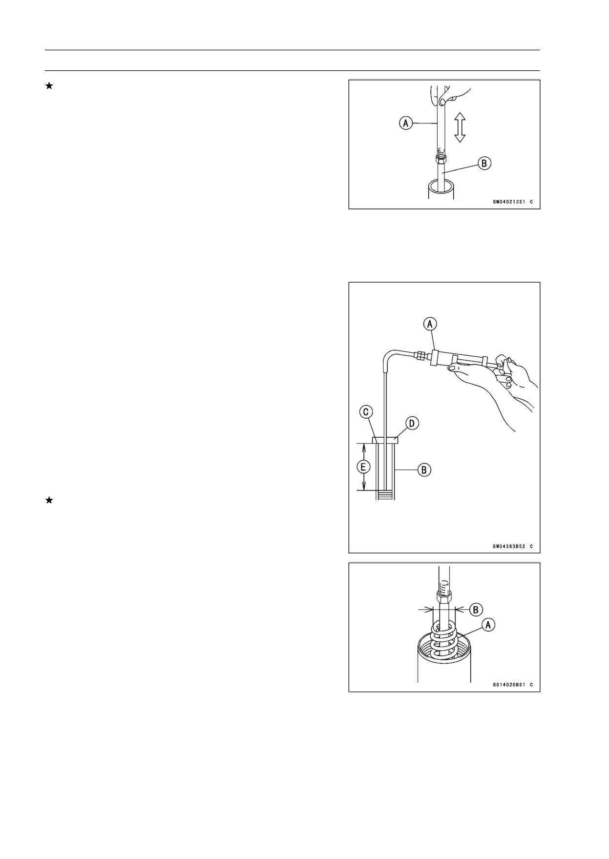
If necessary, measure the oil level as follows.
○Hold the inner tube vertically in a vise.
○Pump the inner tube several times to expel air bubbles.
○Using the piston rod puller [A], move the piston rod [B] up
and down more than ten times in order to expel all the air
from the fork oil.
Special Tool - Fork Piston Rod Puller, M12 × 1.25: 57001
-1289
○Remove the piston rod puller.
○Wait until the oil level settles.
○With the fork fully compressed and the piston rod fully
pushed in, insert a tape measure or rod into the inner
tube, and measure the distance from the top of the inner
tube to the oil.
Oil Level (fully compressed, without spring)
Standard:
88 ±2 mm (3.46 ±0.08 in.)
(from the top of the inner tube)
NOTE
○Fork oil lever may also be measured using the fork oil
level gauge.
Special Tool - Fork Oil Level Gauge [A]: 57001-1290
○With the fork fully compressed and without fork spring,
insert the gauge tube into the inner tube [B] and position
the stopper across the top end [C] of the inner tube.
○Set the gauge stopper [D] so that its lower side shows the
oil level distance specified [E].
○Pull the handle slowly to pump out the excess oil until the
oil no longer comes out.
If no oil is pumped out, there is insufficient oil in the inner
tube. Pour in enough oil, then pump out the excess oil as
shown above.
• Screw the fork piston rod puller onto the end of the piston
rod.
Special Tool - Fork Piston Rod Puller, M12 × 1.25: 57001
-1289
• Pull the puller up above the outer tube top.
• Install the fork spring [A] with the smaller end facing [B]
upward.
• Install:
Collar
Washer
SUSPENSION 13-15
Front Fork
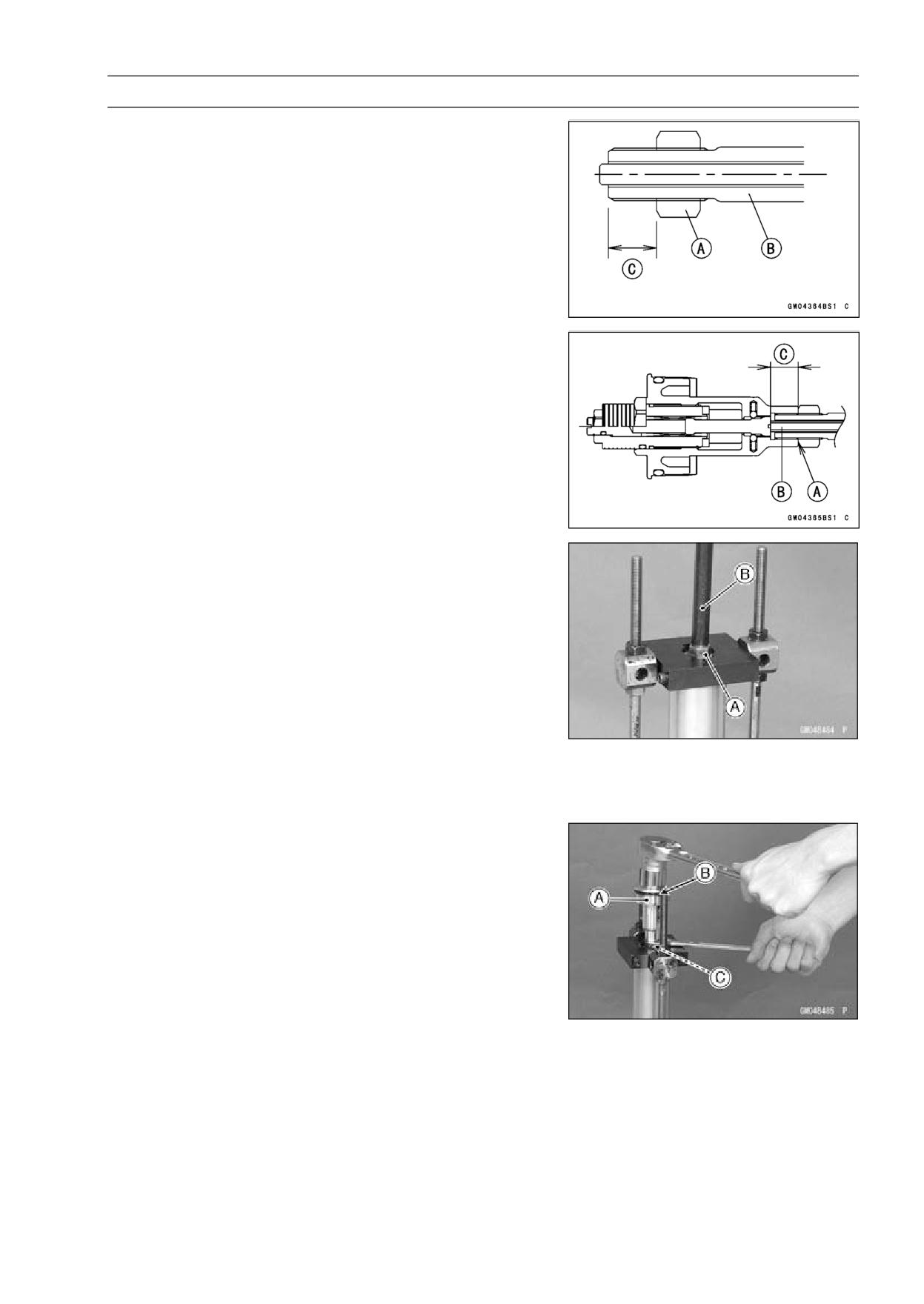
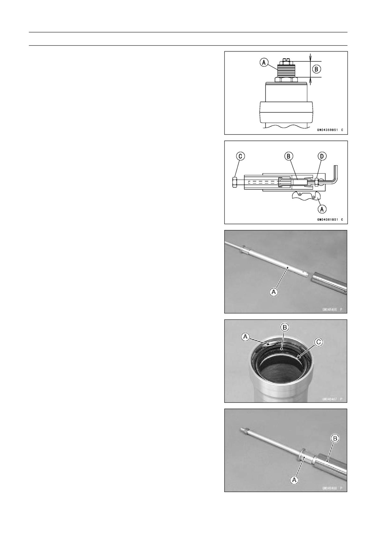
• Screw the rod nut [A] onto the piston rod [B] as shown in
the figure.
11 mm (0.43 in.) [C]
• Check the distance between the bottom end [A] of the
top plug and rebound damping adjuster [B] with a pair of
vernier caliper.
13 mm (0.51 in.) [C]
• Set the fork spring compressor on the washer using the
outer tube as a guide.
Special Tools - Fork Spring Compressor: 57001-1540
Fork Spring Compressor: 57001-1587
NOTE
○Set the clamps so that the cutout of the upper side does
not fit the hole of washer, pull up the outer tube to hold
it by the clamps, and then tighten the two bolts. The
outer tube is used as a guide.
• Hold the piston rod nut [A].
• Remove the piston rod puller [B].
• Install the rebound damping adjuster rod.
• Screw in the top plug [A] stopped onto the piston rod.
• Check the O-ring [B] on the top plug and replace it with a
new one if damaged.
• Holding the top plug with a wrench, tighten the piston rod
nut [C] against the top plug.
Torque - Piston Rod Nut: 28 N·m (2.9 kgf·m, 21 ft·lb)
• While holding up the washer with the clamps, loosen the
fork spring compressor nuts.
• Remove the fork spring compressor.
13-16 SUSPENSION
Front Fork
• Raise the outer tube and screw the top plug into it and
install it to the steering stem.
• Screw in the spring preload adjuster [A] of the top plug
so that the distance between the adjuster top and the top
plug surface is 15 mm (0.59 in.) [B].
• Turn in the rebound damping adjuster until the fully tight-
ened position and turn backward the 5th click.
• Install the front fork (see Front Fork Installation).
Front Fork Disassembly
• Remove the front fork (see Front Fork Removal).
• Drain the fork oil (see Front Fork Oil Change).
• Hold the front fork in a vise [A].
• Stop the cylinder [B] from turning by using the fork cylinder
holder [C].
Special Tool - Fork Cylinder Holder: 57001-1287
• Unscrew the Allen bolt [D], then take the bolt and gasket
out of the bottom of the inner tube.
• Take the cylinder unit [A].
○Do not disassemble the cylinder unit.
• Separate the outer tube from the inner tube.
• Pull out the dust seal.
• Remove the retaining ring [A] from the outer tube.
• Remove the oil seal [B] and washer [C].
Front Fork Assembly
• Replace the following parts with a new one.
Oil Seal
Bottom Allen Bolt Gasket
• Insert the cylinder unit [A] into the inner tube [B].
• Stop the cylinder from turning by using the fork cylinder
holder.
Special Tool - Fork Cylinder Holder: 57001-1287
• Apply a non-permanent locking agent to the thread of the
Allen bolt, and tighten it.
Torque - Front Fork Bottom Allen Bolt: 23 N·m (2.3 kgf·m,
17 ft·lb)
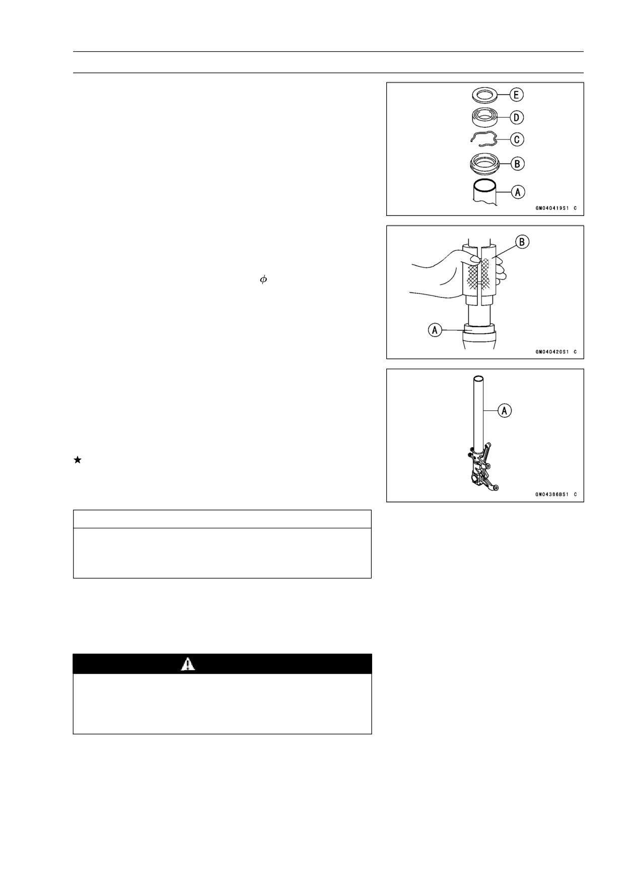
SUSPENSION 13-17
Front Fork
• Install the following parts into the inner tube [A].
Dust Seal [B]
Retaining Ring [C]
Oil Seal [D]
Washer [E]
• Insert the inner tube to the outer tube.
• After installing the washer, install the oil seal [A] by using
the fork oil seal driver [B].
Special Tool - Fork Oil Seal Driver,
43: 57001-1530
• Install the retaining ring and dust seal into the outer tube.
• Pour in the specified type of oil (see Front Fork Oil
Change).
Inner Tube Inspection
• Visually inspect the inner tube [A], and repair any dam-
age.
• Nicks or rust damage can sometimes be repaired by using
a wet-stone to remove sharp edges or raised areas which
cause seal damage.
If the damage is not repairable, replace the inner tube.
Since damage to the inner tube damages the oil seal,
replace the oil seal whenever the inner tube is repaired
or replaced.
CAUTION
If the inner tube is badly bent or creased, replace
it.
Excessive bending, followed by subsequent
straightening, can weaken the inner tube.
• Temporarily assemble the inner and outer tubes, and
pump them back and forth manually to check for smooth
operation.
• If you feel binding or catching, the inner and outer tubes
must be replaced.
WARNING
A straightened inner or outer fork tube may fall in
use, possibly causing an accident. Replace a badly
bent or damaged inner or outer tube and inspect the
other tube carefully before reusing it.
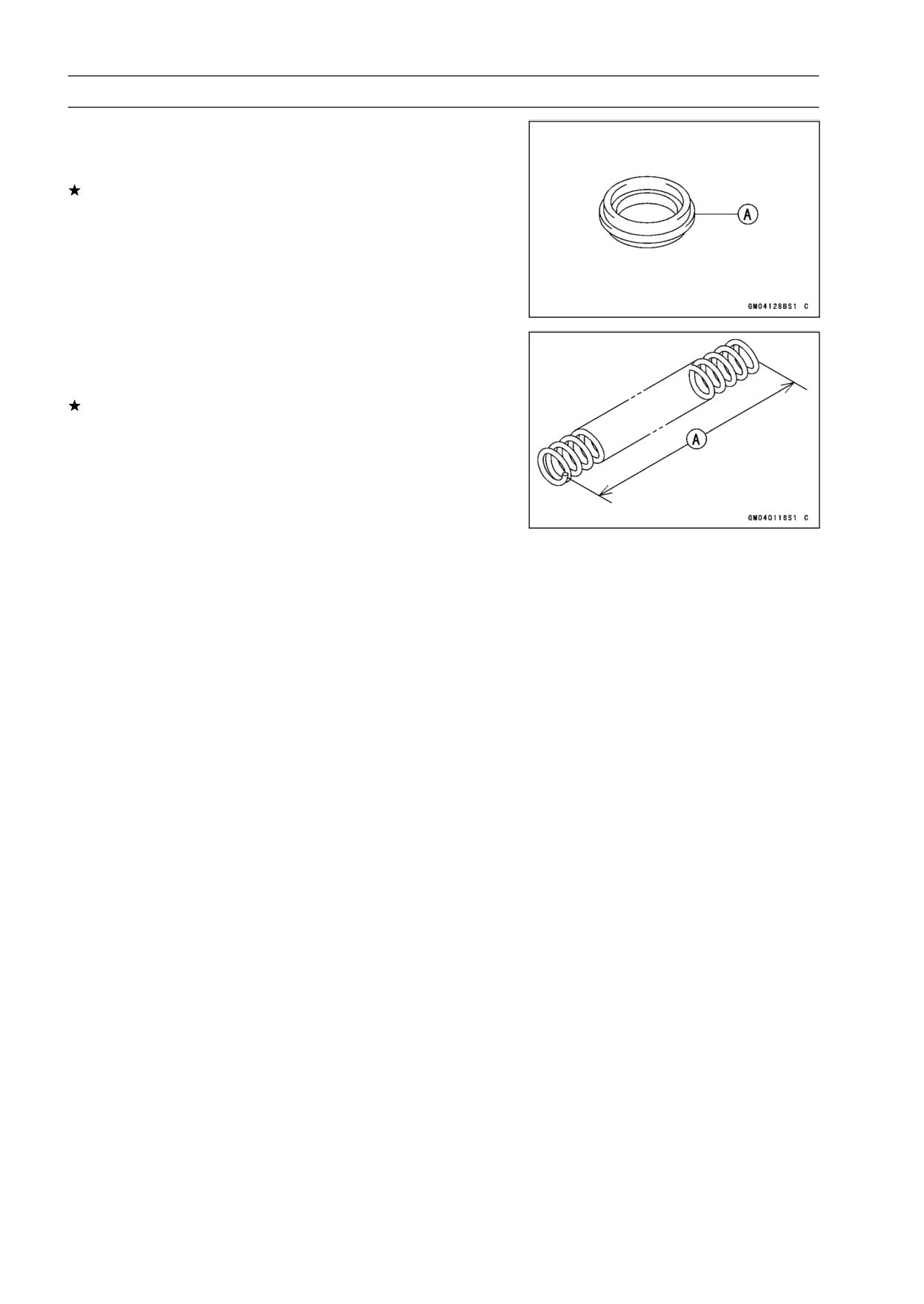
13-18 SUSPENSION
Front Fork
Dust Seal Inspection
• Inspect the dust seal [A] for any signs of deterioration or
damage.
Replace it if necessary.
Spring Tension
• Since a spring becomes shorter as it weakens, check its
free length [A] to determine its condition.
If the spring of either fork leg is shorter than the service
limit, it must be replaced. If the length of a replacement
spring and that of the remaining spring vary greatly, the
remaining spring should also be replaced in order to keep
the fork legs balanced for motorcycle stability.
Spring Free Length
Standard:
257 mm (10.12 in.)
Service Limit:
252 mm (9.92 in.)
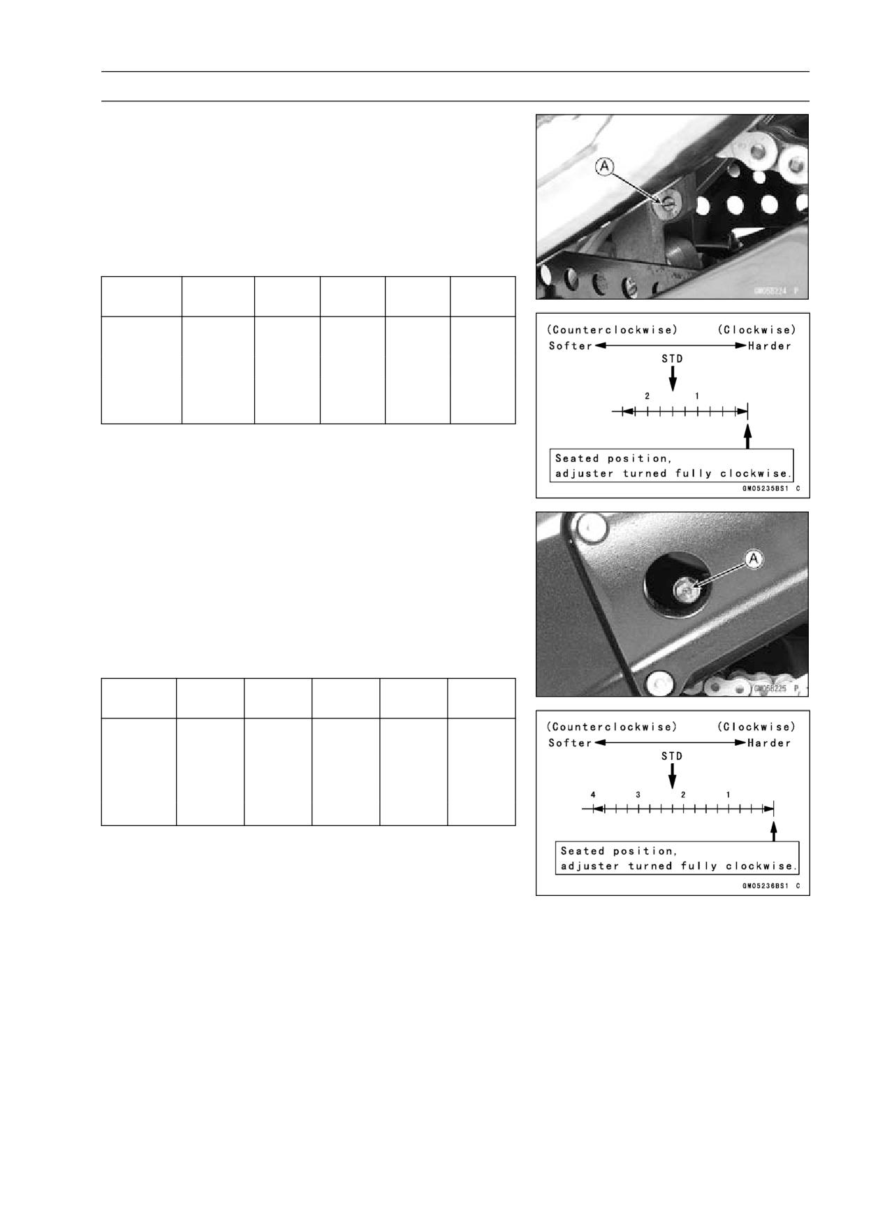
SUSPENSION 13-19
Rear Shock Absorber
Rebound Damping Force Adjustment
• To adjust the rebound damping force, turn the lower
damping adjuster [A] to the desired position, until you
feel a click.
○The standard adjuster setting for an average-build rider
of 68 kg (150 lb) with no passenger and no accessories
is the 1 2/4 turns out from the fully clockwise position.
Rebound Damping Force Adjustment
Adjuster
Damping
Setting
Load
Road
Speed
Position
Force
2 2/4 Turns
Weak
Soft
Light
Good
Low
Out
↑
↑
↑
↑
↑
↑
↓
↓
↓
↓
↓
↓
0
Strong
Hard
Heavy
Bad
High
Compression Damping Force Adjustment
• To adjust the compression damping force, turn the upper
damping adjuster [A] to the desired position until you feel
a click.
○The standard adjuster setting for the average-build rider
of 68 kg (150 lb) with no passenger and no accessories
is the 2 1/4 turns out from the fully clockwise position.
Rebound Damping Force Adjustment
Adjuster
Damping
Setting
Load
Road
Speed
Position
Force
4 Turns
Weak
Soft
Light
Good
Low
Out
↑
↑
↑
↑
↑
↑
↓
↓
↓
↓
↓
↓
0
Strong
Hard
Heavy
Bad
High
Spring Preload Adjustment
• Remove the rear shock absorber from the frame (see
Rear Shock Absorber Removal).
• Loosen the locknut and turn out the adjusting nut to free
the spring.
Special Tool - Hook Wrench T=3.2 R37: 57001-1522
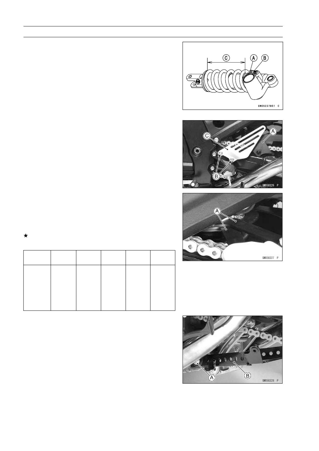
13-20 SUSPENSION
Rear Shock Absorber
• To adjust the spring preload, turn in the adjusting nut [A]
to the desired position and tighten the locknut [B].
Spring Length [C]
Spring Preload Setting
Standard:
Spring length 175.5 mm (6.9 in.)
Usable Range:
Spring length 175.5 ∼ 191.5 mm
(6.909 ∼ 7.539 in.)
○The standard adjusting nut setting for an average-build
rider of 68 kg (150 lb) with no passenger and no acces-
sories is 175.5 mm (6.9 in.) spring length.
• Remove the chain cover [A] (see Drive Chain Removal in
the Final Drive chapter).
• Remove the bolts [B] and left foot guard [C] for turning the
hook wrench easily.
• To adjust the spring preload, turn in the adjusting nut to
the desired position and tighten the locknut by using hook
wrenches [A] with the rear shock absorber attached the
frame.
Special Tool - Hook Wrench T=3.2 R37: 57001-1522
If the spring action feels too soft or too stiff, adjust it.
Spring Adjustment
Adjuster
Damping
Setting
Load
Road
Speed
Position
Force
191.5 mm
Weak
Soft
Light
Good
Low
(7.539 in.)
↑
↑
↑
↑
↑
↑
↓
↓
↓
↓
↓
↓
175.5 mm
(6.909 in.)
Strong
Hard
Heavy
Bad
High
Rear Shock Absorber Removal
• Remove:
Rear Fairing (see Rear Fairing Removal in the Frame
chapter)
Bolts [A] (Both Sides)
Bracket [B]
Lower Fairings (see Lower Fairings Removal in the
Frame chapter).
• Raise the rear wheel off the ground with the jack.
Special Tools - Jack: 57001-1238
Jack Attachment: 57001-1608
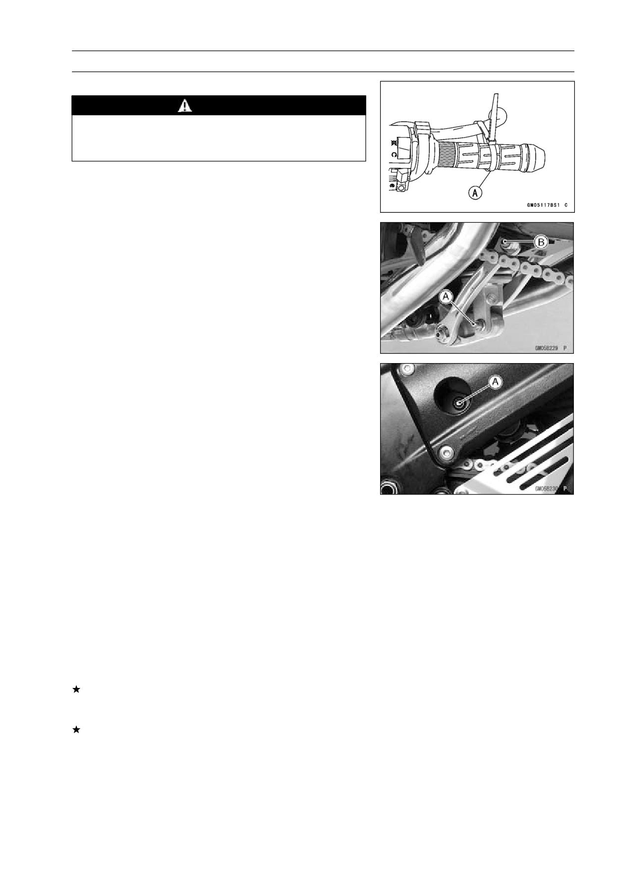
SUSPENSION 13-21
Rear Shock Absorber
• Squeeze the brake lever slowly and it with a band [A].
WARNING
Be sure to hold the front brake when removing the
shock absorber, or the motorcycle may fall over. It
could cause an accident and injury.
• Remove:
Lower Shock Absorber Nut and Bolt [A]
Upper Tie-Rod Nut and Bolt [B]
• Remove the upper shock absorber nut and bolt [A]
• Remove the shock absorber downward.
Rear Shock Absorber Installation
• Tighten:
Torque - Rear Shock Absorber Nuts: 34 N·m (3.5 kgf·m, 25
ft·lb)
Tie-Rod Nuts: 59 N·m (6.0 kgf·m, 44 ft·lb)
Rear Shock Absorber Inspection
• Remove the rear shock absorber (see Rear Shock Ab-
sorber Removal).
• Visually inspect the following items.
Smooth Stroke
Oil Leakage
Crack or Dent
If there is any damage to the rear shock absorber, replace
it.
• Visually inspect the rubber bushing.
If it show any signs of damage, replace it.
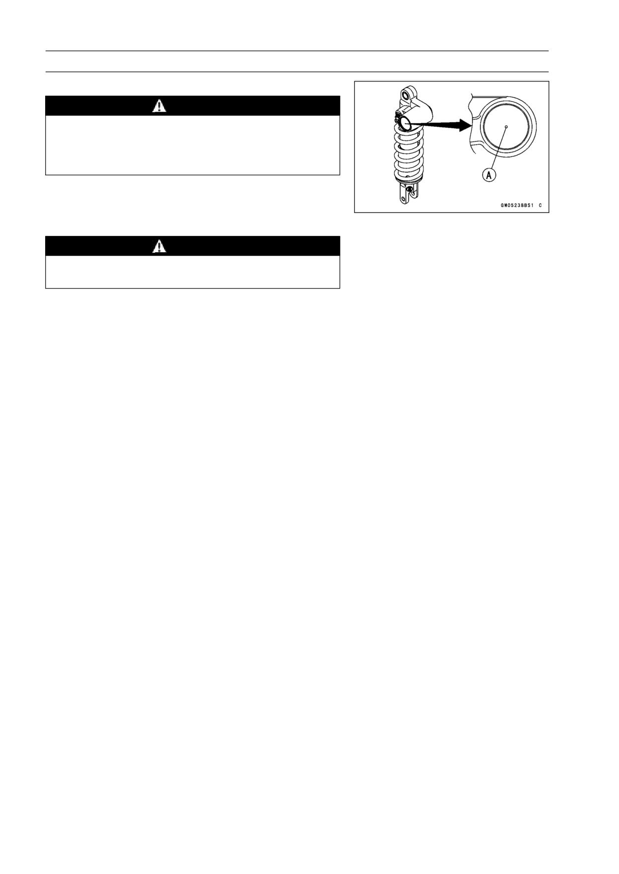
13-22 SUSPENSION
Rear Shock Absorber
Rear Shock Absorber Scrapping
WARNING
Since the reservoir tank of the rear shock absorber
contains nitrogen gas, do not incinerate the reser-
voir tank without first releasing the gas or it may
explode.
• Remove the rear shock absorber (see Rear Shock Ab-
sorber Removal).
• Drill the hole [A] of the reservoir tank using about 2 mm
(0.08 in.) drillbit.
WARNING
Since the high pressure gas is dangerous, do not
point the drill toward your face or body.
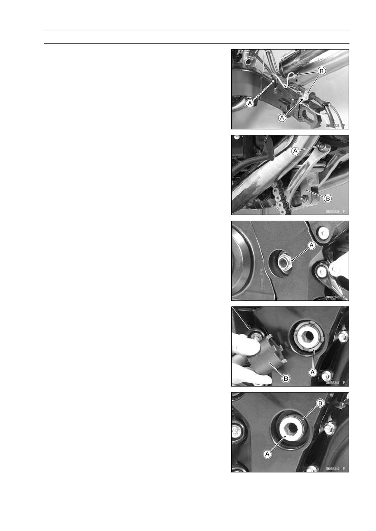
SUSPENSION 13-23
Swingarm
Swingarm Removal
• Remove:
Chain Cover (see Drive Chain Removal in the Final Drive
chapter)
Rear Wheel (see Rear Wheel Removal in the
Wheels/Tires chapter)
Bolts [A]
Brackets [B]
• Remove:
Upper Tie-Rod Nut and Bolt [A]
Rear Shock Absorber [B] (see Rear Shock Absorber Re-
moval)
• Unscrew the swingarm pivot shaft locknut [A].
• Unscrew the swingarm pivot collar locknut [A] using the
nut wrench [B].
Special Tool - Swingarm Pivot Nut Wrench: 57001-1597
• Unscrew the swingarm pivot shaft [A] few times.
○Turn out the swingarm pivot adjusting collar [B].
• Pull out the pivot shaft right side of the motorcycle and
remove the swingarm.
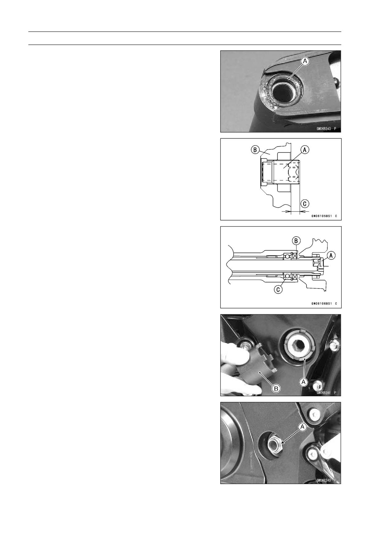
13-24 SUSPENSION
Swingarm
Swingarm Installation
• Apply plenty of grease to the lip of the oil seals [A].
• Install the collar.
• Place the adjusting collar [A] the frame [B] as shown in
the figure.
11 mm (0.43 in.) [C]
• Insert the pivot shaft [A] into the frame from the right side.
• Tighten the pivot shaft so that the clearance between the
adjusting collar [B] and the ball bearing [C] come to 0 mm
(0 in.).
Torque - Swingarm Pivot Adjusting Collar:
20 N·m (2.0
kgf·m, 15 ft·lb)
• Tighten the adjusting collar locknut [A] with the swingarm
pivot nut wrench [B].
Special Tool - Swingarm Pivot Nut Wrench: 57001-1597
Torque - Swingarm Pivot Adjusting Collar Locknut: 98 N·m
(10.0 kgf·m, 72 ft·lb)
• Tighten the pivot shaft nut [A].
Torque - Swingarm Pivot Shaft Nut: 108 N·m (11.0 kgf·m,
80 ft·lb)
• Install the removed parts (see appropriate chapters).
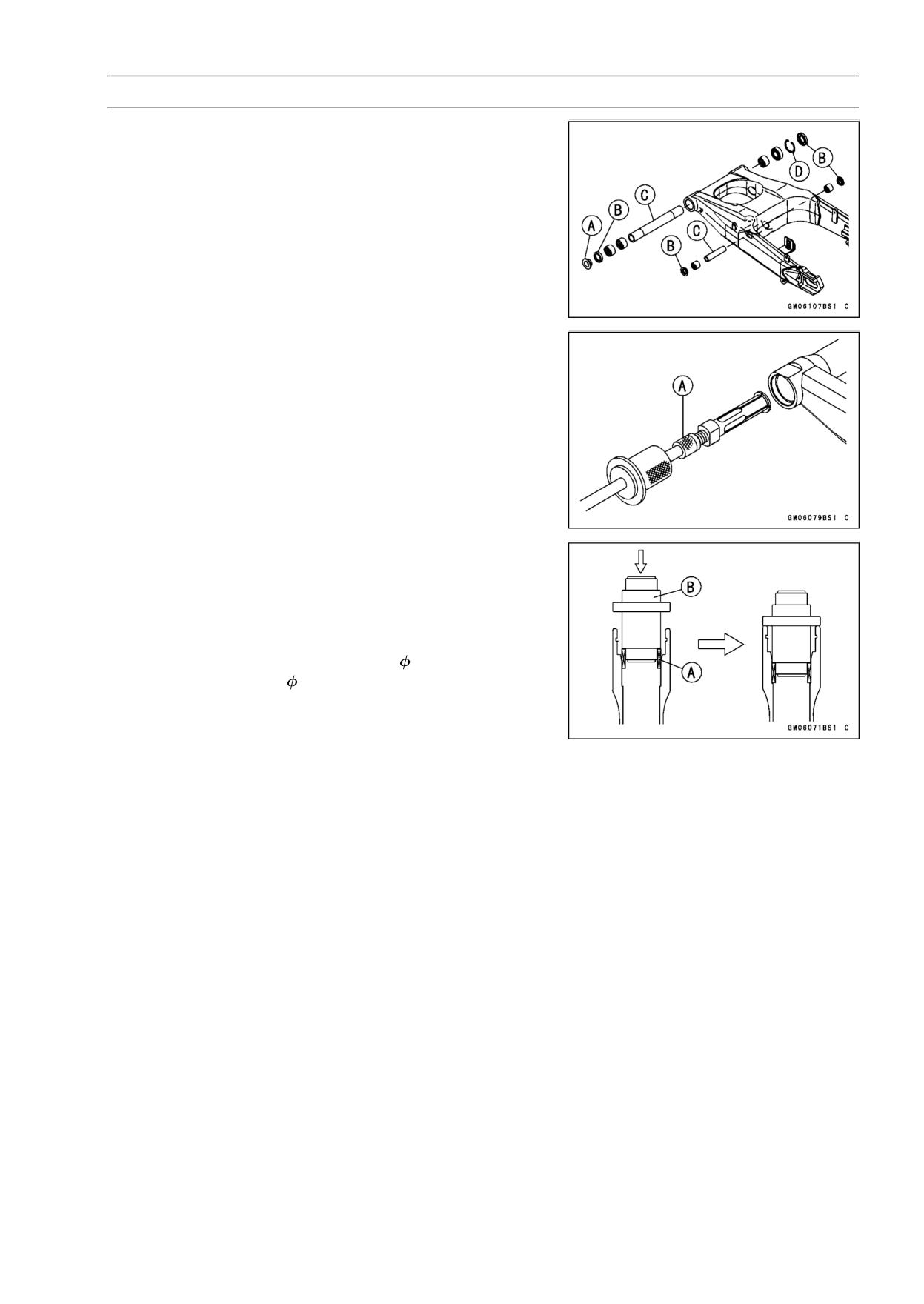
SUSPENSION 13-25
Swingarm
Swingarm Bearing Removal
• Remove:
Swingarm (see Swingarm Removal)
Collar [A]
Oil Seals [B]
Sleeve [C]
Circlip [D] (Right Side)
Special Tool - Inside Circlip Pliers: 57001-143
• Remove the ball bearing and needle bearings.
Special Tool - Oil Seal & Bearing Remover [A]: 57001-1058
Swingarm Bearing Installation
• Replace the ball and needle bearings [A] with new ones.
• Install the ball and needle bearings so that the manufac-
turer’s marks face out.
Special Tools - Bearing Driver Set: 57001-1129
Needle Bearing Driver,
28 [B]: 57001-1610
Spacer
28: 57001-1663
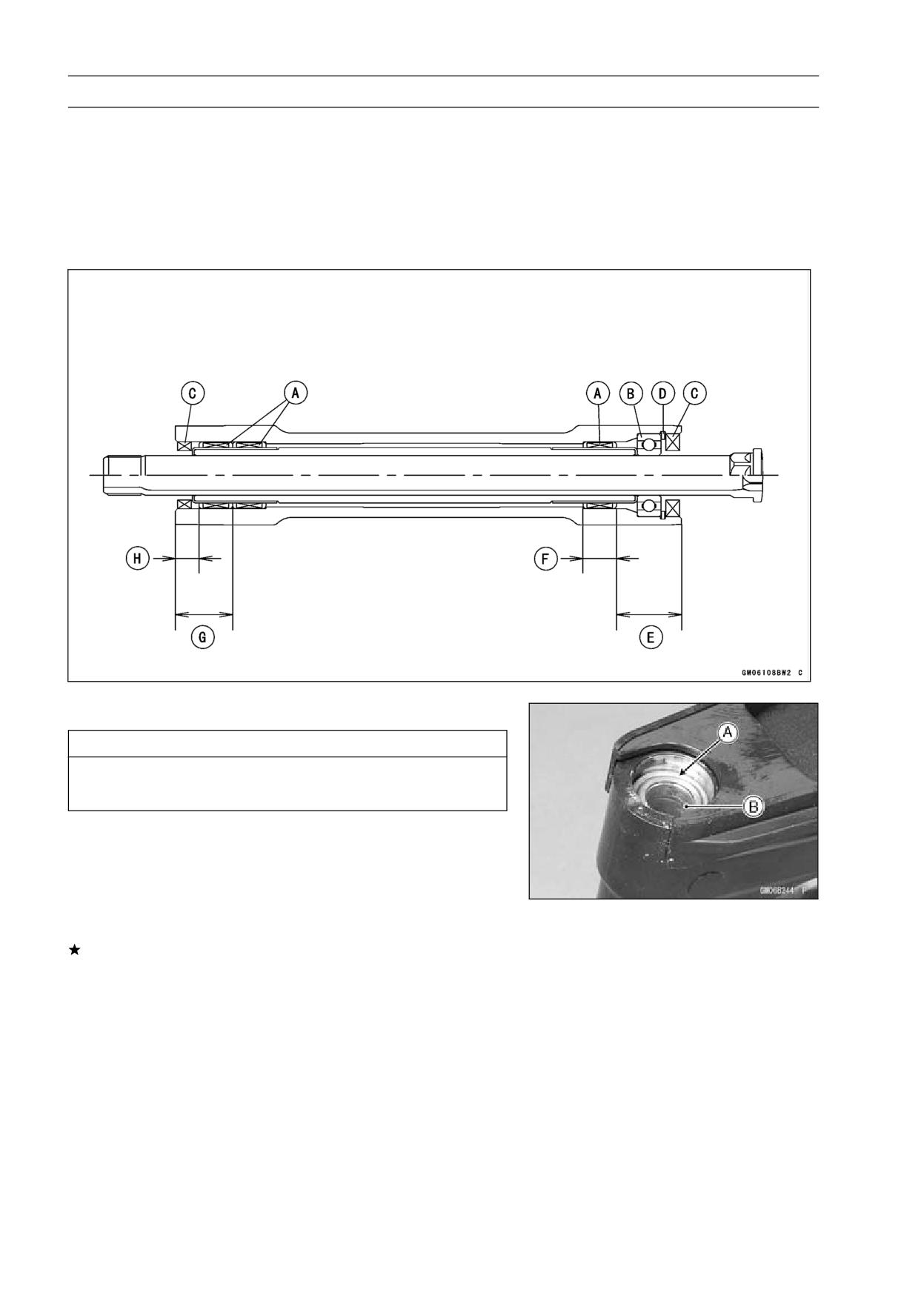
13-26 SUSPENSION
Swingarm
• Install the needle bearings [A], ball bearing [B] and oil
seals [C] position as shown in the figure.
Circlip [D]
32 mm (1.26 in.) [E]
17 mm (0.67 in.) [F]
27.5 mm (1.08 in.) [G]
9.5 mm (0.37 in.) [H]
Swingarm Bearing, Sleeve Inspection
CAUTION
Do not remove the bearings for inspection. Re-
moval may damage them.
• Inspect the needle bearings [A] and ball bearing installed
in the swingarm.
○The rollers and ball in a bearing normally wear very little,
and wear is difficult to measure. Instead of measuring,
visually inspect the bearing for abrasion, discoloration, or
other damage.
If the needle bearing and sleeve [B] show any sings of
abnormal wear, discoloration, or damage, replace them
as a set.
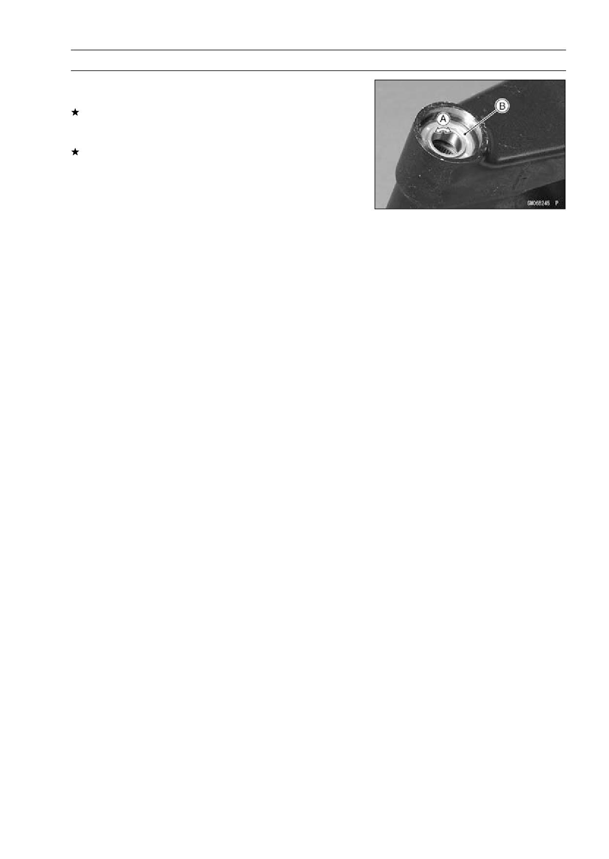
SUSPENSION 13-27
Swingarm
• Turn the bearing in the swingarm back and forth [A] while
checking for plays, roughness, or binding.
If bearing play, roughness, or binding is found, replace
the bearing.
• Examine the bearing seal [B] for tears or leakage.
If the seal is torn or is leaking, replace the bearing.
Chain Guide Inspection
• Refer to the Chain Guide Wear Inspection in the Periodic
Maintenance chapter.
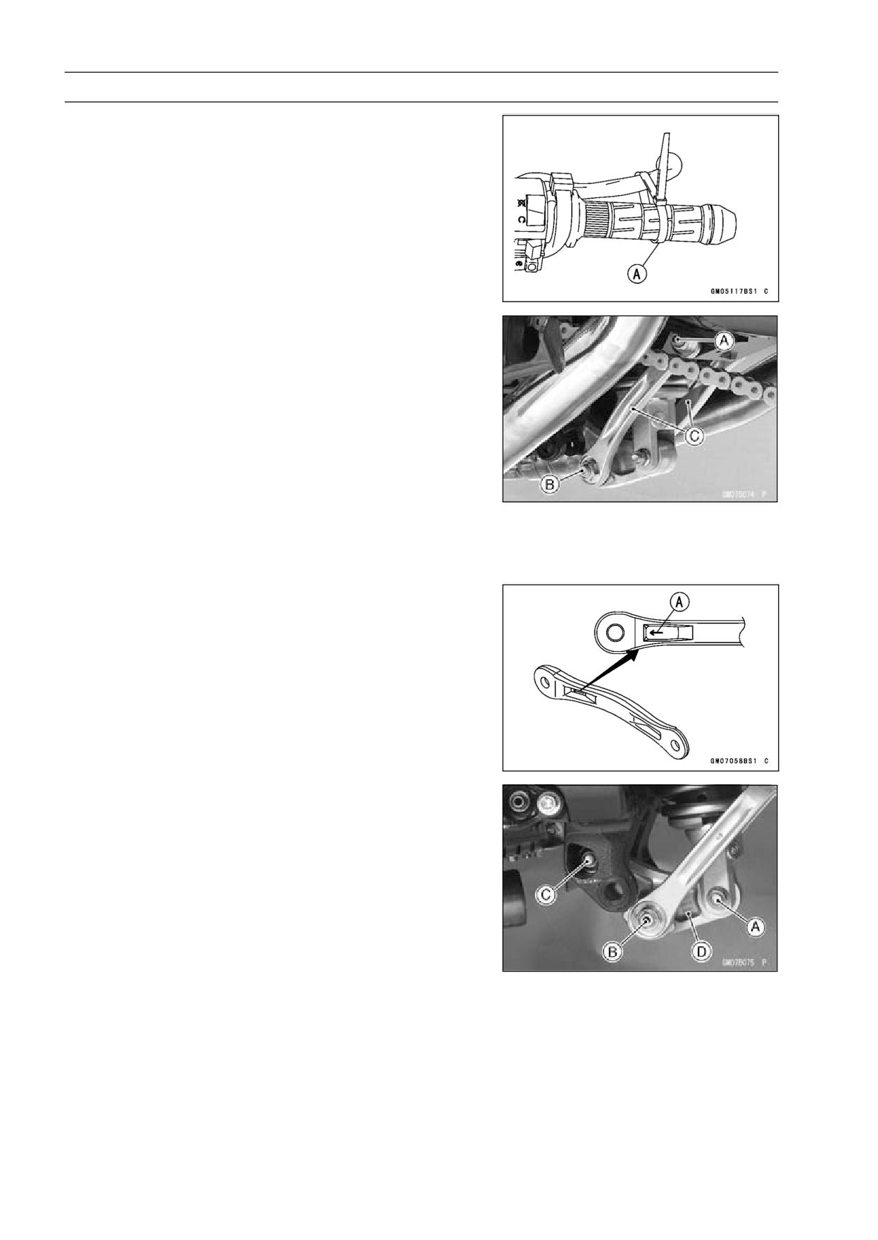
13-28 SUSPENSION
Tie-Rod, Rocker Arm
Tie-Rod Removal
• Squeeze the brake lever slowly and hold it with a band
[A].
• Remove:
Lower Fairings (see Lower Fairing Removal in the Frame
chapter)
Rear Fairing (see Rear Fairing Removal in the Frame
chapter)
Bracket (see Rear Shock Absorber Removal)
• Raise the rear wheel off the ground with the jack.
Special Tools - Jack: 57001-1238
Jack Attachment: 57001-1608
• Remove:
Upper Tie-Rod Nut and Bolt [A]
Lower Tie-Rod Nut and Bolt [B]
Tie-Rods [C]
Tie-Rod Installation
• Apply grease to the inside of the grease seals.
• Install each tie-rod so that the arrow faces [A] forward.
• Tighten:
Torque - Tie-Rod Nuts: 59 N·m (6.0 kgf·m, 44 ft·lb)
Rocker Arm Removal
• Squeeze the brake lever slowly and hold it with a band.
• Remove:
Lower Fairings (see Lower Fairing Removal in the Frame
chapter)
Rear Fairing (see Rear Fairing Removal in the Frame
chapter)
Bracket (see Rear Shock Absorber Removal)
Muffler Bodies (see Muffler Body Removal in the Engine
Top End chapter)
• Raise the rear wheel off the ground with the jack.
Special Tools - Jack: 57001-1238
Jack Attachment: 57001-1608
• Remove:
Lower Rear Shock Absorber Nut and Bolt [A]
Lower Tie-Rod Nut and Bolt [B]
Rocker Arm Nut and Bolt [C]
Rocker Arm [D]
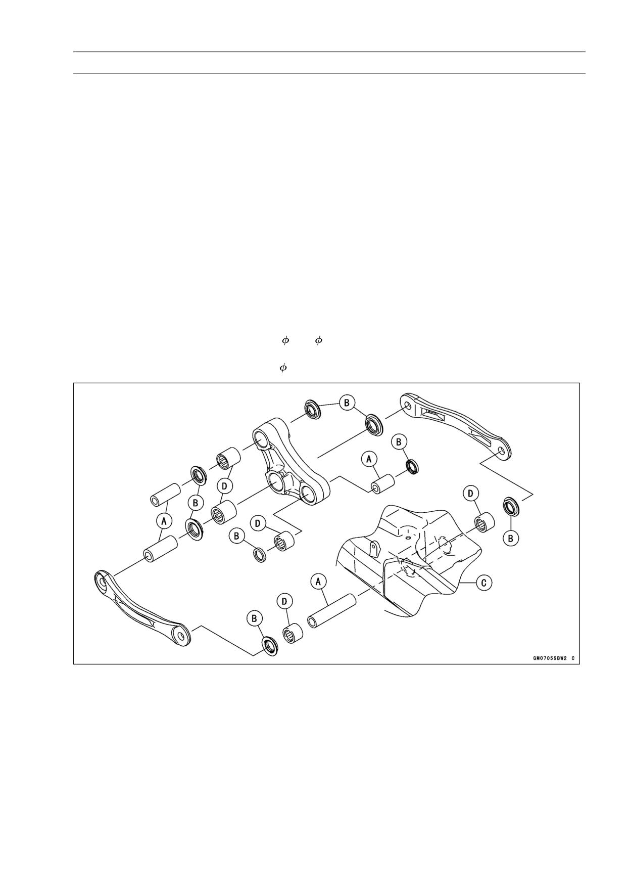
SUSPENSION 13-29
Tie-Rod, Rocker Arm
Rocker Arm Installation
• Apply grease to the inside of the grease seals.
• Tighten:
Torque - Uni-Trak Rocker Arm Nut: 34 N·m (3.5 kgf·m, 25
ft·lb)
Tie-Rod Nuts: 59 N·m (6.0 kgf·m, 44 ft·lb)
Rear Shock Absorber Nut (Lower): 34 N·m (3.5
kgf·m, 25 ft·lb)
Tie-Rod and Rocker Arm Bearing Removal
• Remove:
Tie-Rods (see Tie-Rod Removal)
Rocker Arm (see Rocker Arm Removal)
Sleeves [A]
Oil Seals [B]
Swingarm [C] (see Swingarm Removal)
• Remove the needle bearings [D], using the bearing re-
mover head and bearing remover shaft.
Special Tools - Bearing Remover Head,
20 ×
22: 57001
-1293
Bearing Remover Shaft,
13: 57001-1377
Tie-Rod and Rocker Arm Bearing Installation
• Replace the needle bearing and oil seals with new ones.
• Apply plenty of grease to the lips of the oil seals.
• Install the needle bearings and oil seals position as shown
in the figure.
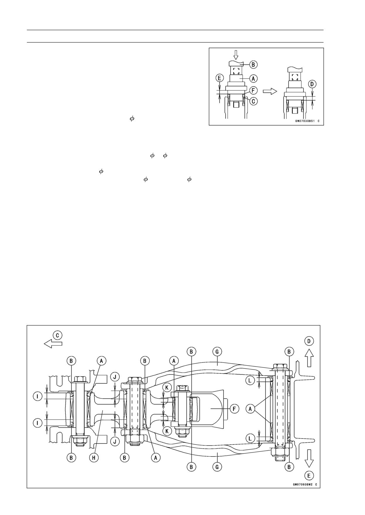
13-30 SUSPENSION
Tie-Rod, Rocker Arm
○Screw the needle bearing driver [A] into the driver holder
[B].
○Insert the needle bearing driver into the needle bearing
[C] and press the needle bearing into the housing until
the driver contacts the end surface of the housing.
Bearing Pressing Depth: 5.5 mm (0.22 in.) [D]
5.0 mm (0.20 in.) [E]
NOTE
○For a bearing of inner diameter 18, select the pressing
side of the needle bearing driver according to its press-
ing depth.
Special Tools - Bearing Driver Set: 57001-1129
Needle Bearing Driver,
17/
18:
57001
-1609
Spacer,
18 [F]: 57001-1636
Needle Bearing Driver,
20 & Spacer,
28:
57001-1678
NOTE
○Install the needle bearings so that the marked side
faces in.
Needle Bearing [A]
Oil Seals [B]
Front [C]
Right Side [D]
Left Side [E]
Rear Shock Absorber [F]
Tie-Rods [G]
Rocker Arm [H]
7.5 mm (0.30 in.) [I]
10 mm (0.39 in.) [J]
5.5 mm (0.22 in.) [K]
5.0 mm (0.20 in.) [L]
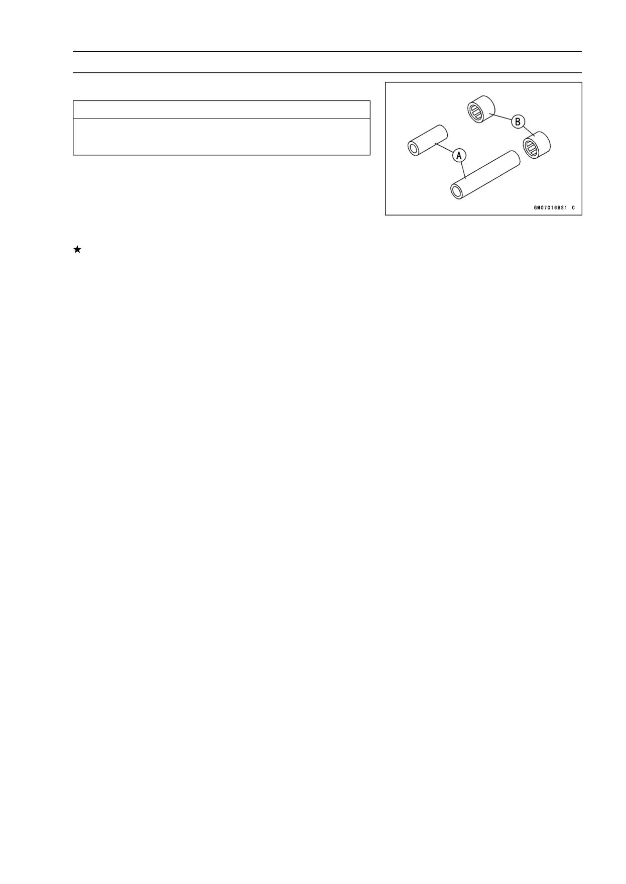
SUSPENSION 13-31
Tie-Rod, Rocker Arm
Rocker Arm/Tie-Rod Bearing, Sleeve Inspection
CAUTION
Do not remove the bearings for inspection. Re-
moval may damage them.
• Visually inspect the locker arm, or tie-rod sleeves [A] and
needle bearings [B].
• The rollers in a needle bearing normally wear very little,
and wear is difficult to measure. Instead of measuring,
inspect the bearing for abrasion, color change, or other
damage.
If there is any doubt as to the condition of any of the nee-
dle bearings or sleeve, replace the sleeve and needle
bearings as a set.
Rocker Arm/Tie-Rod Bearing Lubrication
NOTE
○Since the bearings are packed with grease, lubrication
is not required.
STEERING 14-1
Steering
Table of Contents
Exploded View
14-2
Special Tools
14-4
Steering
14-5
Steering Inspection
14-5
Steering Adjustment
14-5
Steering Stem
14-6
Stem, Stem Bearing Removal
14-6
Stem, Stem Bearing Installation
14-7
Steering Stem Bearing Lubrication
14-9
Steering Stem Warp
14-9
Stem Cap Deterioration, Damage
14-9
Handlebar
14-10
Handlebar Removal
14-10
Handlebar Installation
14-10
14
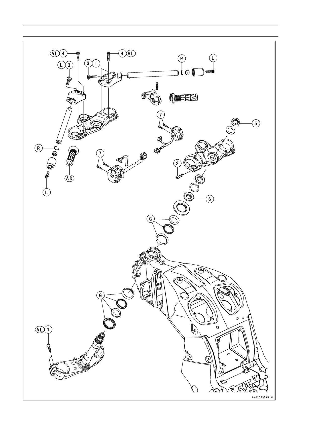
14-2 STEERING
Exploded View

STEERING 14-3
Exploded View
Torque
No.
Fastener
Remarks
N·m
kgf·m
ft·lb
1
Front Fork Clamp Bolts (Lower)
30
3.1
22
AL
2
Front Fork Clamp Bolts (Upper)
20
2.0
15
3
Handlebar Bolts
34
3.5
25
L
4
Handlebar Holder Bolts
25
2.5
18
AL
5
Steering Stem Head Nut
78
8.0
58
6
Steering Stem Nut
23
2.3
17
7
Switch Housing Screws
3.5
0.36
31 in·lb
AD: Apply adhesive.
AL: Tighten the two clamp bolts alternately two times to ensure even tightening torque.
G: Apply grease.
L: Apply a non-permanent locking agent.
R: Replacement Parts
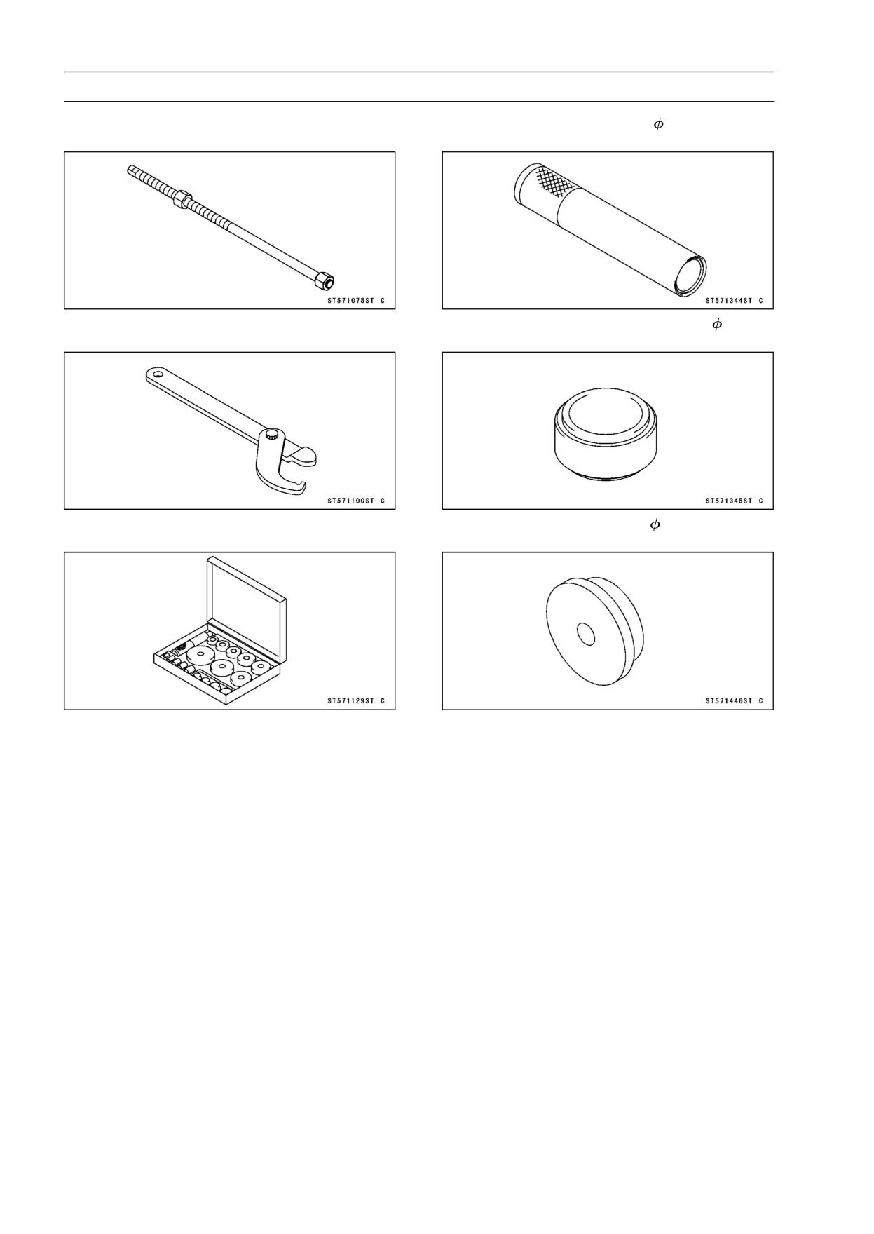
14-4 STEERING
Special Tools
Head Pipe Outer Race Press Shaft:
Steering Stem Bearing Driver,
42.5:
57001-1075
57001-1344
Steering Stem Nut Wrench:
Steering Stem Bearing Driver Adapter,
41.5:
57001-1100
57001-1345
Bearing Driver Set:
Head Pipe Outer Race Driver,
55:
57001-1129
57001-1446
STEERING 14-5
Steering
Steering Inspection
• Refer to the Steering Play Inspection in the Periodic Main-
tenance chapter.
Steering Adjustment
• Refer to the Steering Play Adjustment in the Periodic
Maintenance chapter.
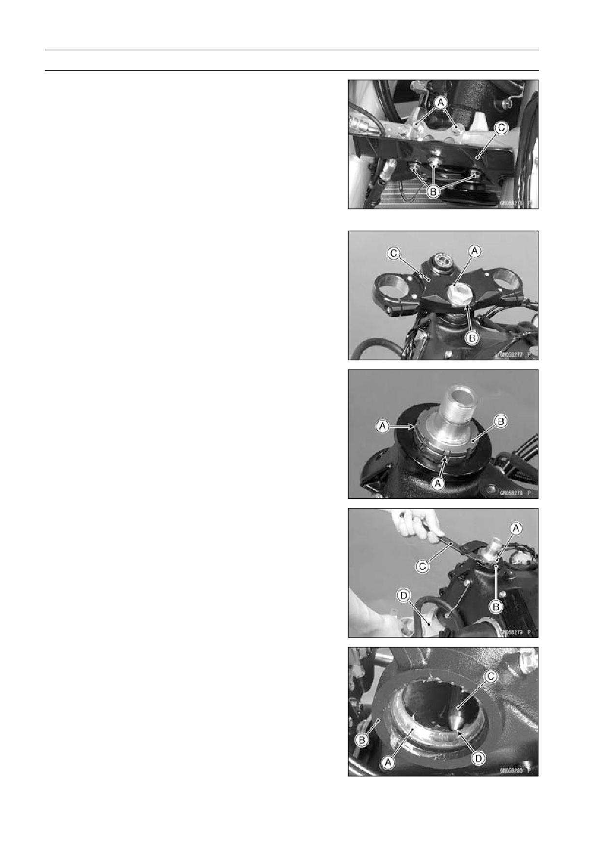
14-6 STEERING
Steering Stem
Stem, Stem Bearing Removal
• Remove:
Upper Fairing (see Upper Fairing Removal in the Frame
chapter)
Front Wheel (see Front Wheel Removal in the
Wheels/Tires chapter)
Handlebars (see Handlebar Removal)
Front Forks (see Front Fork Removal in the Suspension
chapter)
Bracket Bolts [A]
Cover Bolts [B] and Cover [C]
• Remove:
Steering Stem Head Nut [A] and Washer [B]
Steering Stem Head [C]
• Bend the claws [A] of lock washer straighten.
• Remove the steering stem locknut [B].
Special Tool - Steering Stem Nut Wrench: 57001-1100
• Remove the lock washer.
• Pushing up the stem base, and remove the steering stem
nut [A] with stem cap [B].
Special Tool - Steering Stem Nut Wrench [C]: 57001-1100
• Remove:
Steering Stem [D]
Upper Ball Bearing Inner Race and Ball Bearing
• To remove the ball bearing outer races [A] pressed into
the head pipe [B], insert a bar [C] into the recesses [D]
of head pipe, and applying it to both recess alternately
hammer it to drive the race out.
NOTE
○If either steering stem bearing is damaged, it is recom-
mended that both the upper and lower bearings (includ-
ing outer races) should be replaced with new ones.
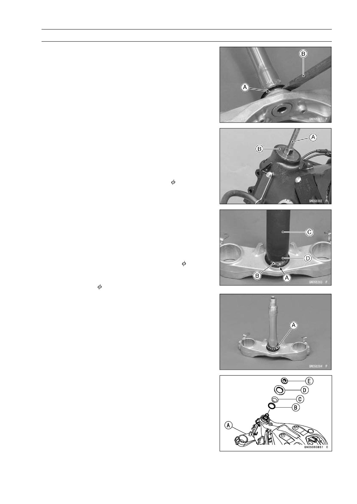
STEERING 14-7
Steering Stem
• Remove the lower ball bearing inner race (with its oil seal)
[A] which is pressed onto the steering stem with a suitable
commercially available chisel [B].
Stem, Stem Bearing Installation
• Replace the bearing outer races with new ones.
• Drive them into the head pipe at the same time.
Special Tools - Head Pipe Outer Race Press Shaft [A]:
57001-1075
Bearing Driver Set: 57001-1129
Head Pipe Outer Race Driver,
55 [B]: 57001
-1446
• Apply grease to the outer races.
• Replace the bearing inner races and oil seal with new
ones.
• Apply grease to the oil seal.
• Install the oil seal [A] on the steering stem, and drive the
lower ball bearing inner race [B] applied the grease onto
the stem.
Special Tools - Steering Stem Bearing Driver,
42.5 [C]:
57001-1344
Steering Stem Bearing Driver Adapter,
41.5 [D]: 57001-1345
• Install the lower ball bearing [A] onto the stem.
• Grease the following.
Inner and Outer Races
Lower and Upper Ball Bearings
○The lower and upper ball bearings are identical.
• Install the stem [A] through the head pipe and install the
ball bearing [B] and inner race [C] on it.
• Install:
Stem Cap [D]
Steering Stem Nut [E]
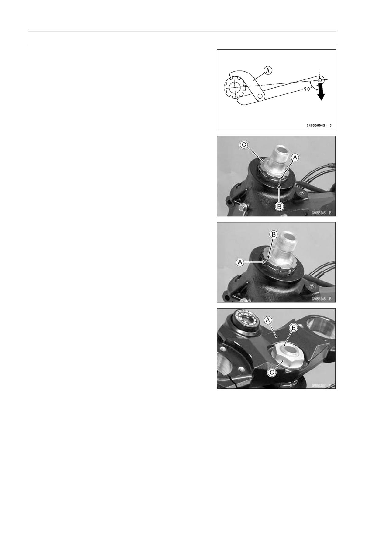
14-8 STEERING
Steering Stem
• Settle the bearings in place as follows.
○Tighten the steering stem nut with 55 N·m (5.6 kgf·m, 41
ft·lb) of torque first, and loosen it a fraction of a turn until
it turns lightly. Afterward tighten it again with specified
torque using a steering stem nut wrench [A].
Special Tool - Steering Stem Nut Wrench: 57001-1100
Torque - Steering Stem Nut: 23 N·m (2.3 kgf·m, 17 ft·lb)
• Install the lock washer so that claw [A] of washer fit the
notch [B] of steering stem locknut [C].
• First tighten the steering stem locknut by hand until the
resistance is felt fully, then tighten the steering stem lock
nut so that align the claw [A] of stem lock nut to the notch
[B] of stem nut by hand.
• Check that there is no play and the steering stem turns
smoothly without rattles. If not, the steering stem bearing
may be damaged.
• Bend the claw of lock washer to steering stem nut notch.
• Install the stem head [A] to the steering stem [B].
• Install the washer, and temporary tighten the stem head
nut [C].
• Install the front forks (see Front Fork Installation in the
Suspension chapter).
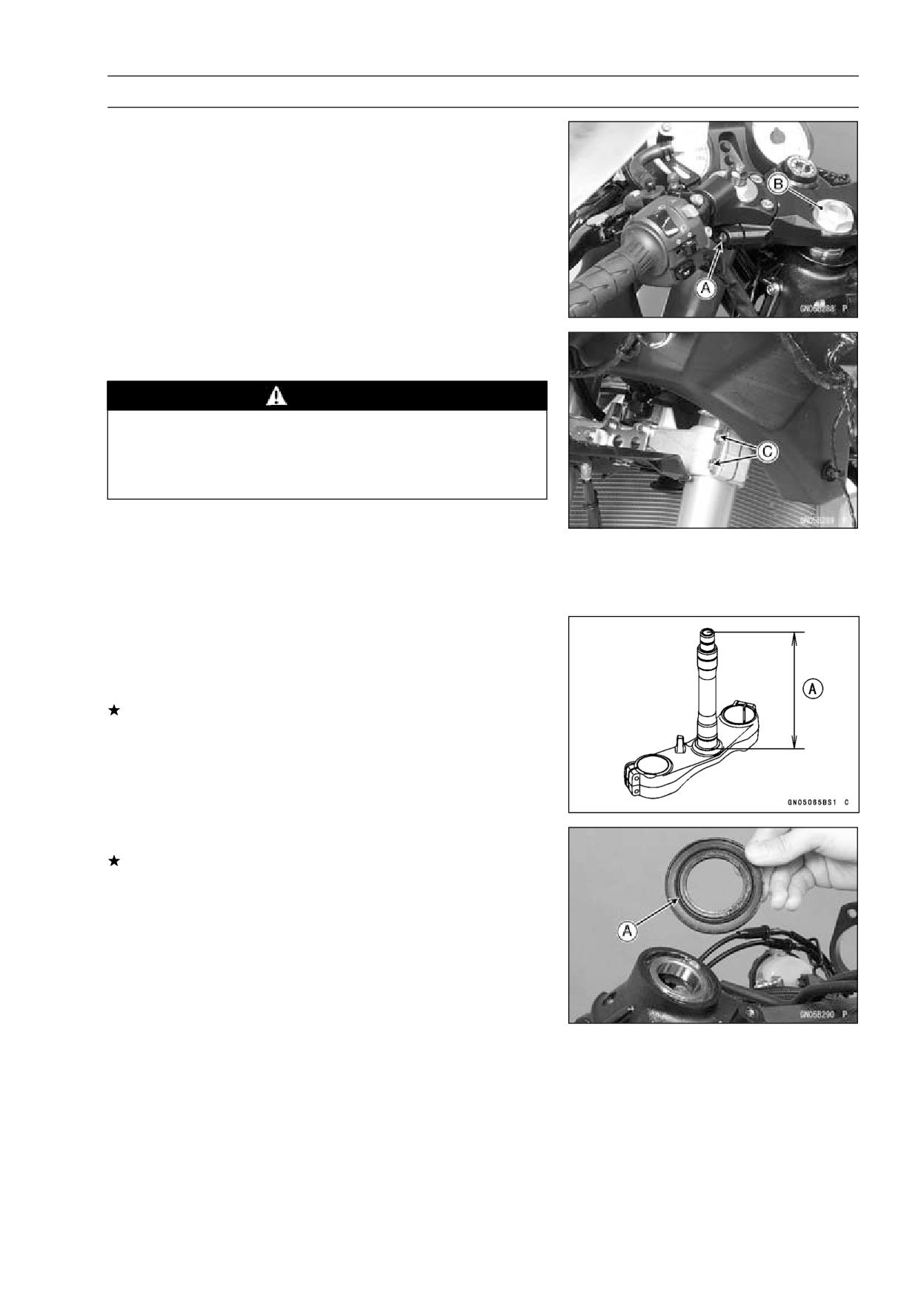
STEERING 14-9
Steering Stem
NOTE
○Tighten the upper front fork clamp bolts [A] first, next the
stem head nut [B], last the lower front fork clamp bolts
[C].
○Tighten the two lower fork clamp bolts alternately two
times to ensure even tightening torque.
Torque - Front Fork Clamp Bolts (Upper):
20 N·m (2.0
kgf·m, 15 ft·lb)
Steering Stem Head Nut: 78 N·m (8.0 kgf·m, 58
ft·lb)
Front Fork Clamp Bolts (Lower):
30 N·m (3.1
kgf·m, 22 ft·lb)
WARNING
Do not impede the handlebar turning by routing the
cables, harnesses and hoses improperly (see Ca-
ble, Wire, and Hose Routing section in the Appen-
dix chapter).
• Install the removed parts (see appropriate chapters).
Steering Stem Bearing Lubrication
• Refer to the Steering Stem Bearing Lubrication in the Pe-
riodic Maintenance chapter.
Steering Stem Warp
• Whenever the steering stem is removed, or if the steering
can not be adjusted for smooth action, check the steering
stem for straightness.
If the steering stem [A] is bent, replace the steering stem.
Stem Cap Deterioration, Damage
Replace the stem cap if its oil seal [A] shows damage.
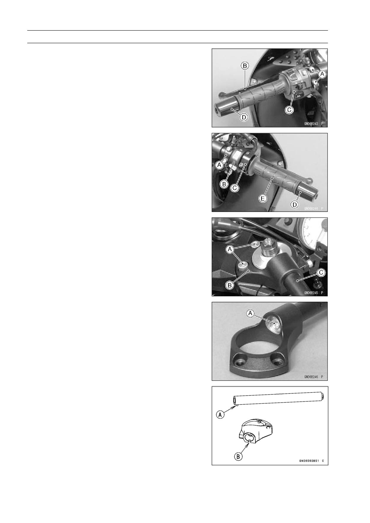
14-10 STEERING
Handlebar
Handlebar Removal
• Remove:
Clutch Lever Clamp Bolts [A]
Clutch Lever Assembly [B]
Left Switch Housing [C]
Handlebar Weight [D]
• Remove:
Front Master Cylinder [A] (see Front Master Cylinder Re-
moval in the Brakes chapter)
Right Switch Housing [B]
Throttle Case [C]
Handlebar Weight [D]
Throttle Grip [E]
• Unscrew the handlebar holder bolts [A].
• Remove each handlebar holder [B] with handlebar [C].
• Hold the handlebar in a vise, and unscrew the handlebar
bolt [A].
• Remove the handlebar.
• Remove the left handlebar grip.
Handlebar Installation
• Apply adhesive cement to the inside of the left handlebar
grip.
• Fit the pin [A] of the handlebar to the recess [B] of the
handlebar holder.
• Apply a non-permanent locking agent to the threads of
the handlebar bolts.
• Tighten:
Torque - Handlebar Bolts: 34 N·m (3.5 kgf·m, 25 ft·lb)
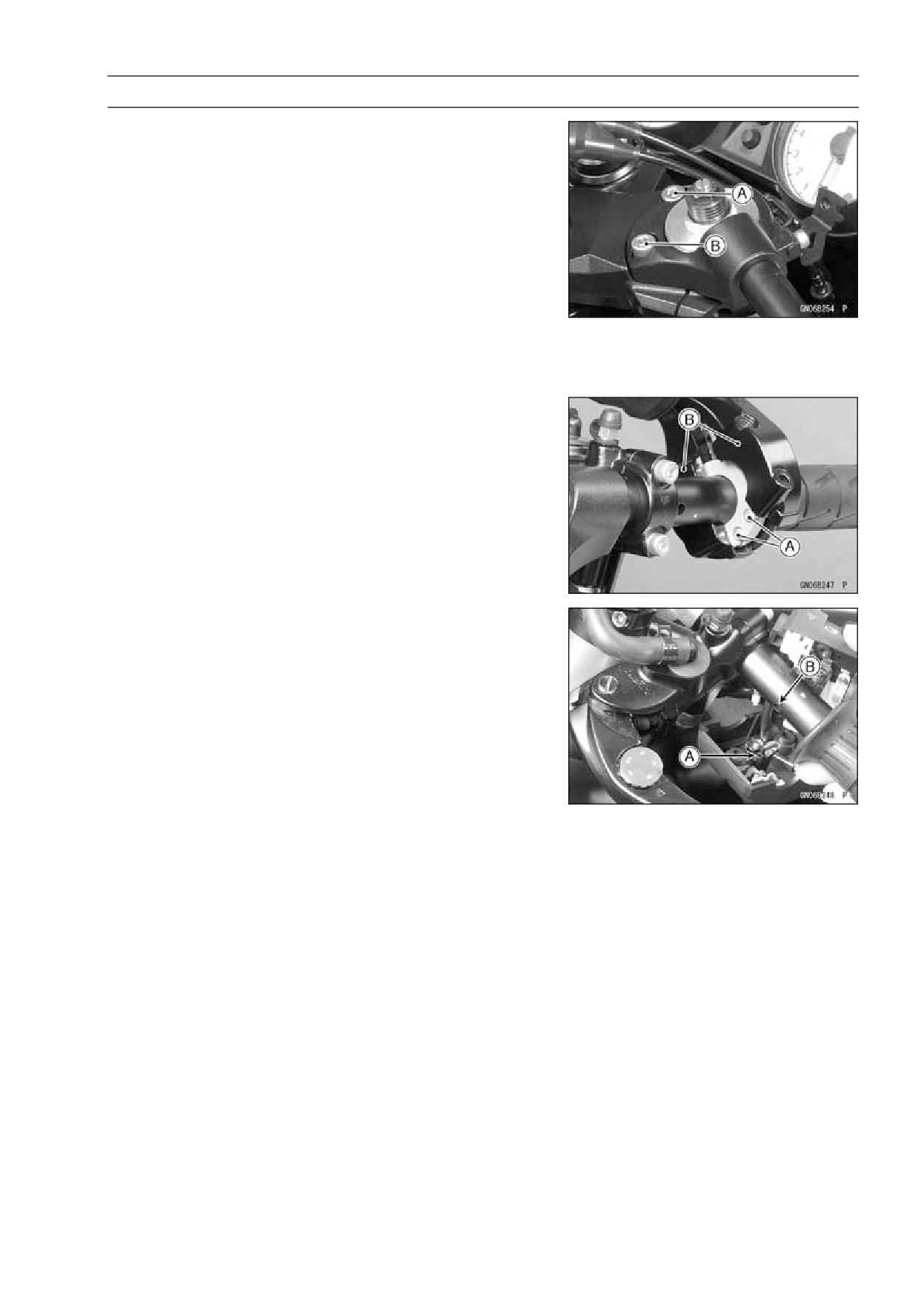
STEERING 14-11
Handlebar
• Install the handlebar holder with handlebar on the steering
stem head.
• Tighten the handlebar holder bolts.
NOTE
○Tighten the handlebar holder bolt [A] first, next the han-
dlebar holder bolt [B].
○Tighten the two handlebar holder bolts alternately two
times to ensure even tightening torque.
Torque - Handlebar Holder Bolts:
25 N·m (2.5 kgf·m, 18
ft·lb)
• Install the front master cylinder (see Front Master Cylinder
Installation in the Brakes chapter).
• Install:
Throttle Grip
Throttle Cable Tips [A]
Throttle Cases [B]
○Fit the projection into a small hole in the handlebar.
• Apply a non-permanent locking agent to the threads of
the handlebar weight bolts, and tighten them.
• Install the left and right switch housings.
○Fit the projection [A] into a small hole [B] in the handlebar.
Torque - Switch Housing Screws: 3.5 N·m (0.36 kgf·m, 31
in·lb)
• Install the clutch lever (see Clutch Lever Installation in the
Clutch chapter).
FRAME 15-1
Frame
Table of Contents
Exploded View
15-2
Seat
15-10
Seat Removal
15-10
Seat Installation
15-10
Fairings
15-11
Lower Fairing Removal
15-11
Lower Fairing Installation
15-11
Fairing Cover Removal
15-11
Middle Fairing Removal
15-11
Middle Fairing Installation
15-12
Windshield Removal
15-12
Windshield Installation
15-13
Upper Fairing Removal
15-13
Upper Fairing Disassembly
15-13
Upper Fairing Assembly
15-13
Upper Fairing Installation
15-14
Inner Cover Removal
15-14
Inner Cover Installation
15-14
Upper Inner Fairing Removal
15-14
Upper Inner Fairing Installation
15-15
Upper Fairing Bracket Removal
15-15
Upper Fairing Bracket Installation
15-15
Inner Fairing Removal
15-15
Inner Fairing Installation
15-15
Rear Fairing Removal
15-15
Rear Fairing Installation
15-15
Seat Cover
15-16
Seat Cover Removal
15-16
Seat Cover Installation
15-16
Fenders
15-18
15
Front Fender Removal
15-18
Front Fender Installation
15-18
Flap and Rear Fender Removal
15-18
Flap and Rear Fender Installation
15-19
Frame
15-20
Rear Frame Removal
15-20
Rear Frame Installation
15-20
Frame Inspection
15-20
Center Stand, Sidestand
15-21
Center Stand Removal (Equipped Models)
15-21
Center Stand Installation (Equipped Models)
15-21
Sidestand Removal
15-21
Sidestand Installation
15-21
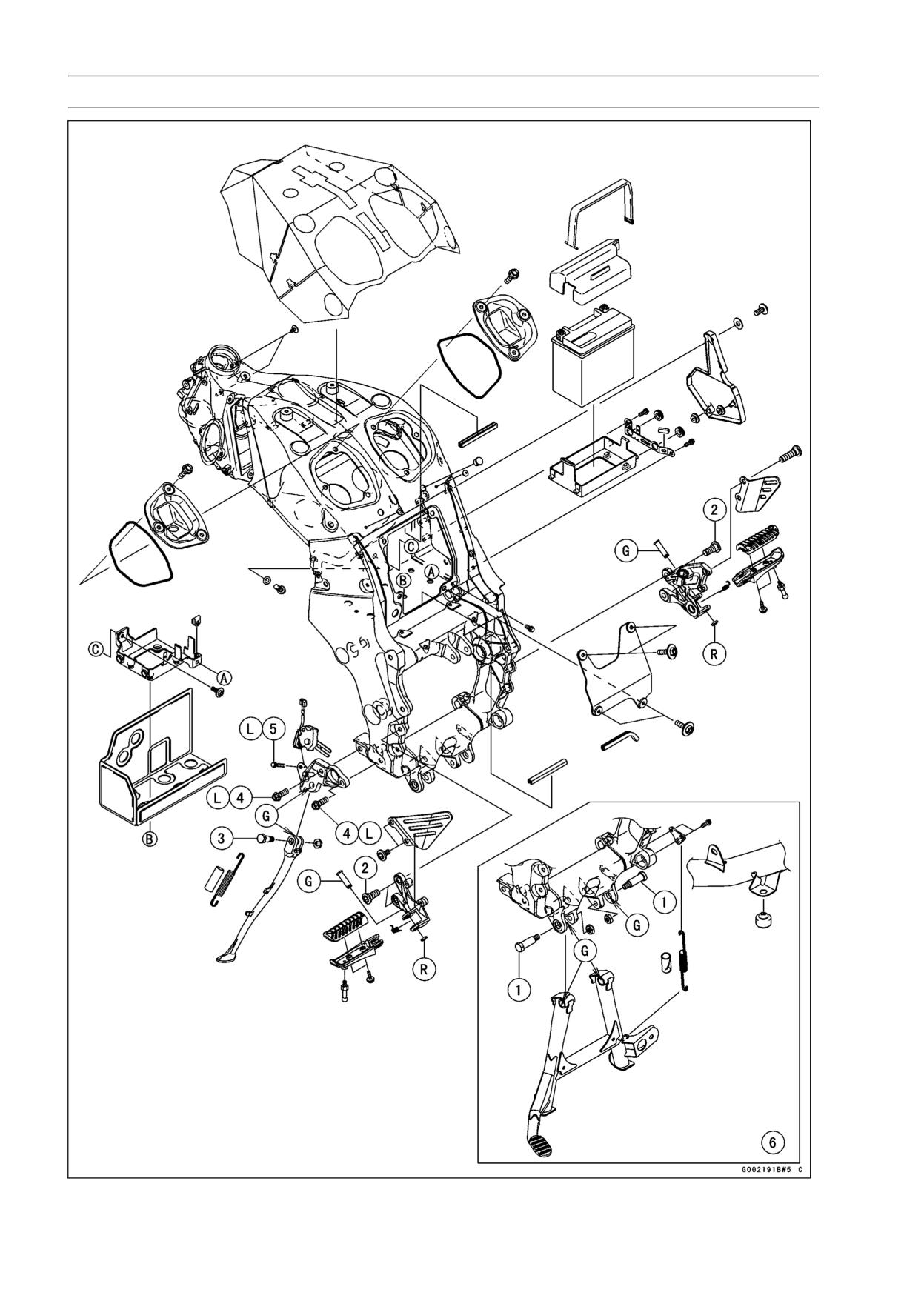
15-2 FRAME
Exploded View
FRAME 15-3
Exploded View
Torque
No.
Fastener
Remarks
N·m
kgf·m
ft·lb
1
Center Stand Bolts
44
4.5
32
2
Front Footpeg Bracket Bolts
25
2.5
18
3
Sidestand Bolt
44
4.5
32
4
Sidestand Bracket Bolts
49
5.0
36
L
5
Sidestand Switch Bolt
8.8
0.90
78 in·lb
L
6. Center Stand (Equipped Models)
G: Apply grease.
L: Apply a non-permanent locking agent.
R: Replacement Parts
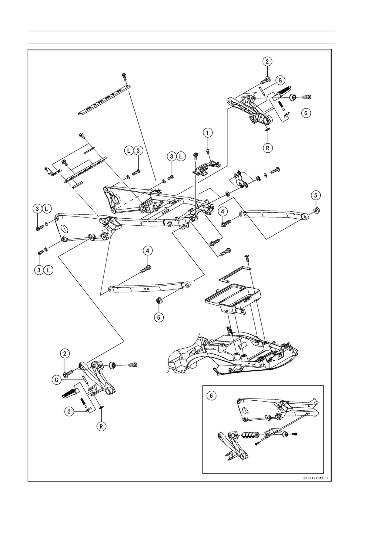
15-4 FRAME
Exploded View
FRAME 15-5
Exploded View
Torque
No.
Fastener
Remarks
N·m
kgf·m
ft·lb
1
Rear Fender Mounting Screws
1.2
0.12
11 in·lb
2
Rear Footpeg Bracket Bolts
25
2.5
18
3
Rear Frame Bolts
44
4.5
32
L
4
Rear Frame Pipe Bolts
44
4.5
32
5
Rear Frame Pipe Nuts
44
4.5
32
6. Center Stand Grip (Equipped Models)
G: Apply grease.
L: Apply a non-permanent locking agent.
R: Replacement Parts
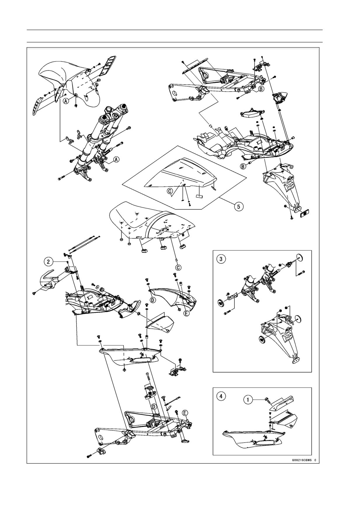
15-6 FRAME
Exploded View
FRAME 15-7
Exploded View
Torque
No.
Fastener
Remarks
N·m
kgf·m
ft·lb
1
Grab Rail Mounting Bolts
25
2.5
18
2
Seat Lock Bracket Screws
1.2
0.12
11 in·lb
3. Reflector (United States and Canada Models)
4. Grab Rail (Equipped Models)
5. Seat Cover (Equipped Models)
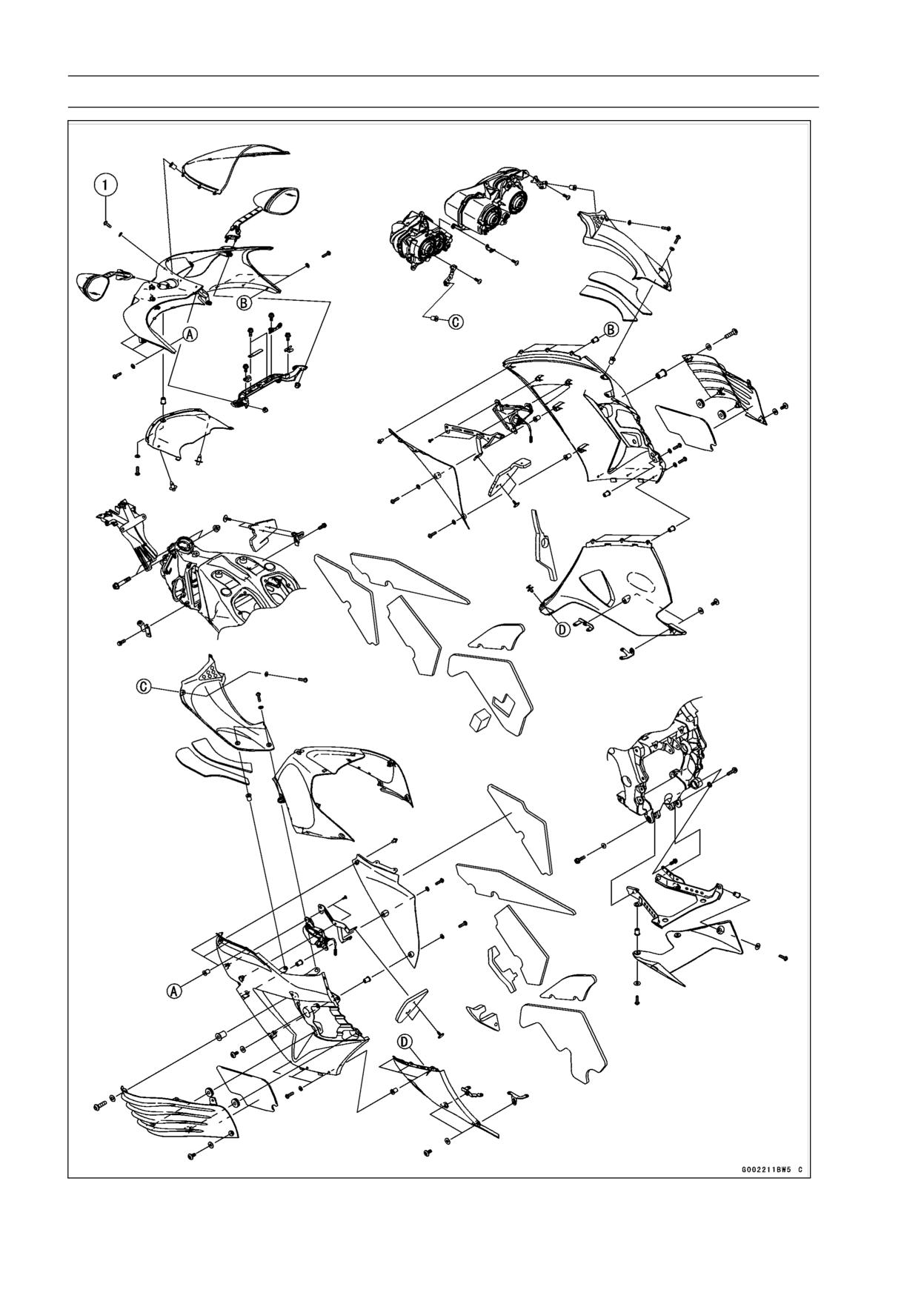
15-8 FRAME
Exploded View
FRAME 15-9
Exploded View
Torque
No.
Fastener
Remarks
N·m
kgf·m
ft·lb
1
Windshield Mounting Bolts
0.42
0.043
3.7 in·lb