Kawasaki ZZR 1400, ZZR1400 ABS, Ninja ZX-14 Motorcycle. Service Manual (2006-2007 year) - page 2
3-26 FUEL SYSTEM (DFI)
Troubleshooting the DFI System
Even when the DFI system is operating normally, the
warning indicator light (LED) goes on and FI warning
message and FI warning symbol may be displayed under
strong electrical interference. Additional measures are not
required. Turn the ignition switch OFF to stop the indicator
light, message and symbol.
If the warning indicator light (LED) of the motorcycle
brought in for repair still goes on, check the service code.
When the repair has been done, the warning indicator
light (LED) goes off and FI warning message and FI warning
symbol are not displayed on the LCD. But the service codes
stored in memory of the ECU are not erased to preserve
the problem history. The problem history can be referred
using the KDS (Kawasaki Diagnostic System) when solving
unstable problems
Much of the DFI system troubleshooting work consists
of confirming continuity of the wiring. The DFI parts are
assembled and adjusted with precision, and it is impossible
to disassemble or repair them.
• When checking the DFI parts, use a digital meter which
can be read two decimal place voltage or resistance.
○The DFI part connectors have seals, including the ECU.
When measuring the input or output voltage with the
connector joined, use the needle adapter set. Insert the
needle adapter inside the seal until the needle adapter
reaches the terminal.
Special Tool - Needle Adapter Set: 57001-1457
CAUTION
Insert the needle adapter straight along the terminal
in the connector to prevent short-circuit between
terminals.
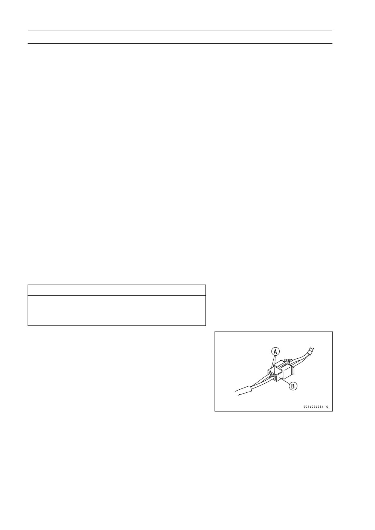
○After measurement, remove the needle adapters and ap-
ply silicone sealant to the seals [A] of the connector [B]
for waterproofing.
Sealant - Kawasaki Bond (Silicone Sealant):
56019-120
-Seals of Connector
FUEL SYSTEM (DFI) 3-27
Troubleshooting the DFI System
• Always check battery condition before replacing the DFI
parts. A fully charged battery is a must for conducting
accurate tests of the DFI system.
• Trouble may involve one or in some cases all items.
Never replace a defective part without determining what
CAUSED the problem. If the problem was caused by
some other item or items, they too must be repaired or
replaced, or the new replacement part will soon fail again
• Measure coil winding resistance when the DFI part is cold
(at room temperature)
• Do not adjust or remove the throttle sensor.
• Do not directly connect a 12 V battery to a fuel injector.
Insert a resistor (5 ∼ 7 Ω ) or a bulb (12 V × 3 ∼ 3.4 W) in
series between the battery and the injector.
• The DFI parts have been adjusted and set with precision.
Therefore, they should be handled carefully, never strike
sharply, as with a hammer, or allowed to drop on a hard
surface. Such a shock to the parts can damage them.
• Check wiring and connections from the ECU connector
to the suspected faulty DFI parts, using the hand tester
(special tool, analog tester) rather than a digital tester.
Special Tool - Hand Tester: 57001-1394
• Make sure all connectors in the circuit are clean and tight,
and examine wires for signs of burning, fraying, etc. Dete-
riorated leads and bad connections can cause reappear-
ance of problems and unstable operation of the DFI sys-
tem.
If any wiring is deteriorated, replace the wiring.
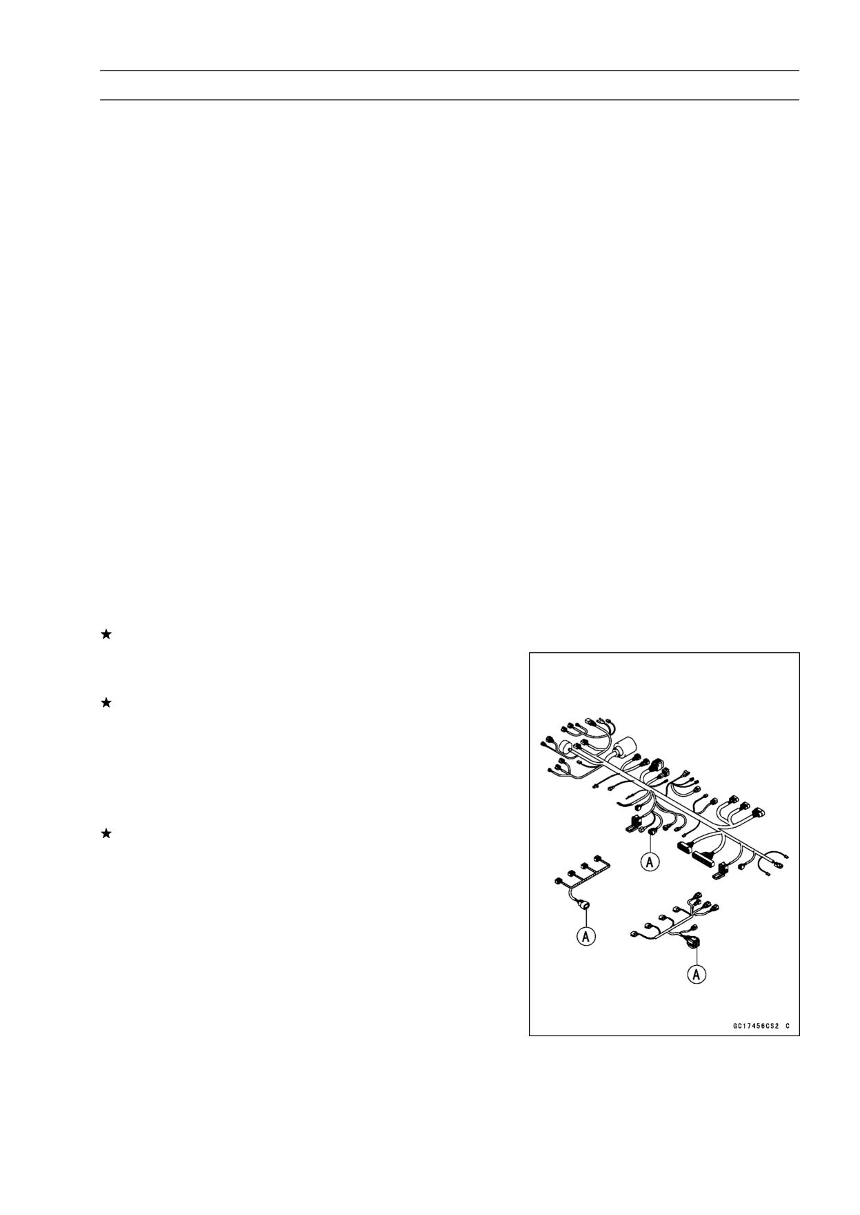
• Pull each connector [A] apart and inspect it for corrosion,
dirt, and damage.
If the connector is corroded or dirty, clean it carefully. If it
is damaged, replace it. Connect the connectors securely.
• Check the wiring for continuity.
○Use the wiring diagram to find the ends of the lead which
is suspected of being a problem.
○Connect the hand tester between the ends of the leads.
○Set the tester to the × 1 Ω range, and read the tester.
If the tester does not read 0 Ω, the lead is defective. Re-
place the lead or the main harness or the sub harness.
3-28 FUEL SYSTEM (DFI)
Troubleshooting the DFI System
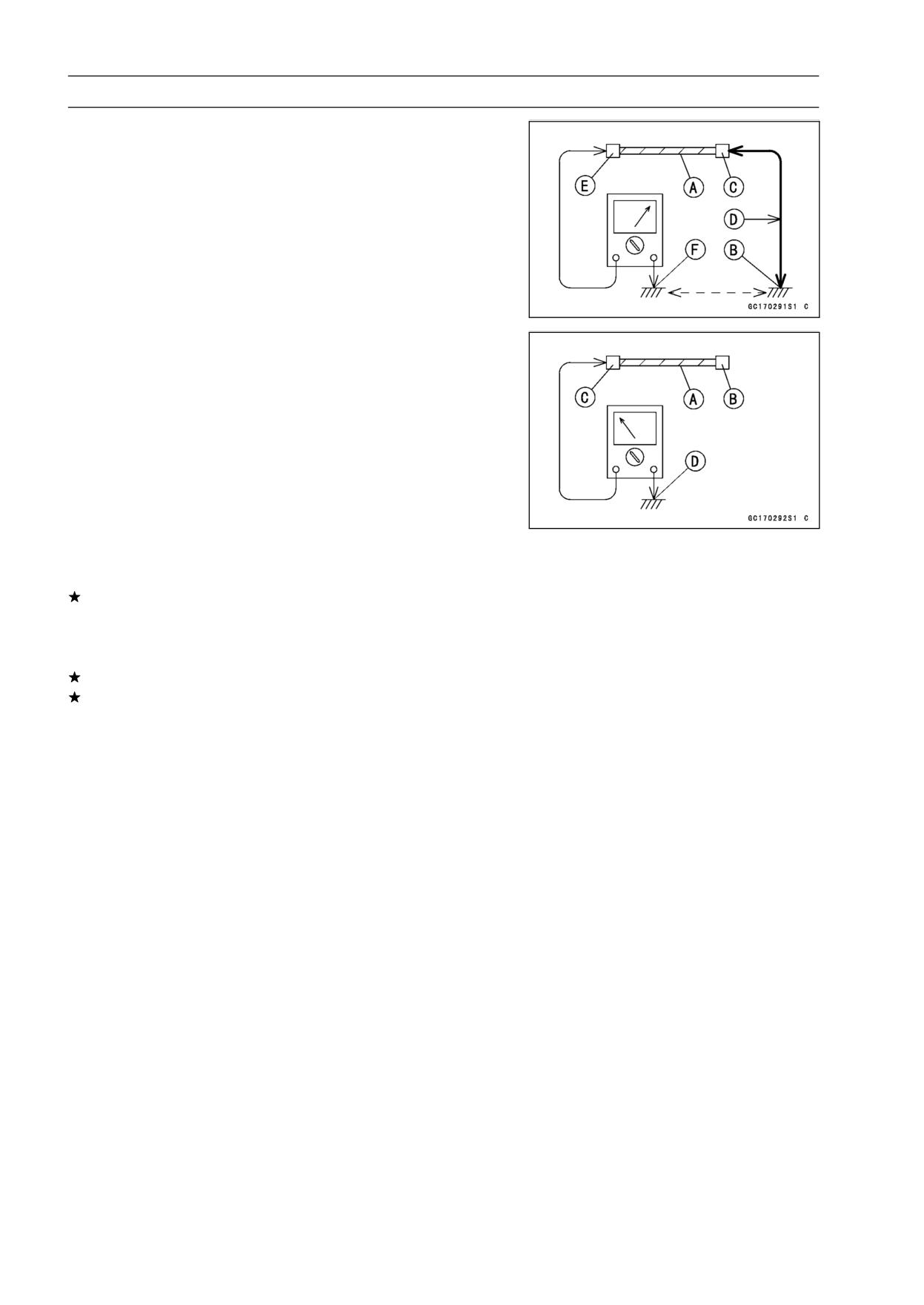
○If both ends of a harness [A] are far apart, ground [B] the
one end [C], using a jumper lead [D] and check the con-
tinuity between the end [E] and the ground [F]. This en-
ables to check a long harness for continuity. If the harness
is open, repair or replace the harness.
○When checking a harness [A] for short circuit, open one
end [B] and check the continuity between the other end
[C] and ground [D]. If there is continuity, the harness has
a short circuit to ground, and it must be repaired or re-
placed.
• Narrow down suspicious locations by repeating the con-
tinuity tests from the ECU connectors.
If no abnormality is found in the wiring or connectors, the
DFI parts are the next likely suspects. Check the part,
starting with input and output voltages. However, there is
no way to check the ECU itself.
If an abnormality is found, replace the affected DFI part.
If no abnormality is found in the wiring, connectors, and
DFI parts, replace the ECU.
○The diagnosis flow chart illustrates the above procedures.
○After inspection, be sure to connect all the DFI electrical
connectors. Do not turn the ignition switch ON while the
DFI electrical connectors and ignition system connectors
are disconnected. Otherwise, the ECU memorizes ser-
vice codes as open circuit.
○Lead Color Codes:
BK: Black
G: Green
P: Pink
BL: Blue
GY: Gray
PU: Purple
BR: Brown
LB: Light Blue
R: Red
CH: Chocolate
LG: Light Green
W: White
DG: Dark Green
O: Orange
Y: Yellow
FUEL SYSTEM (DFI) 3-29
Troubleshooting the DFI System
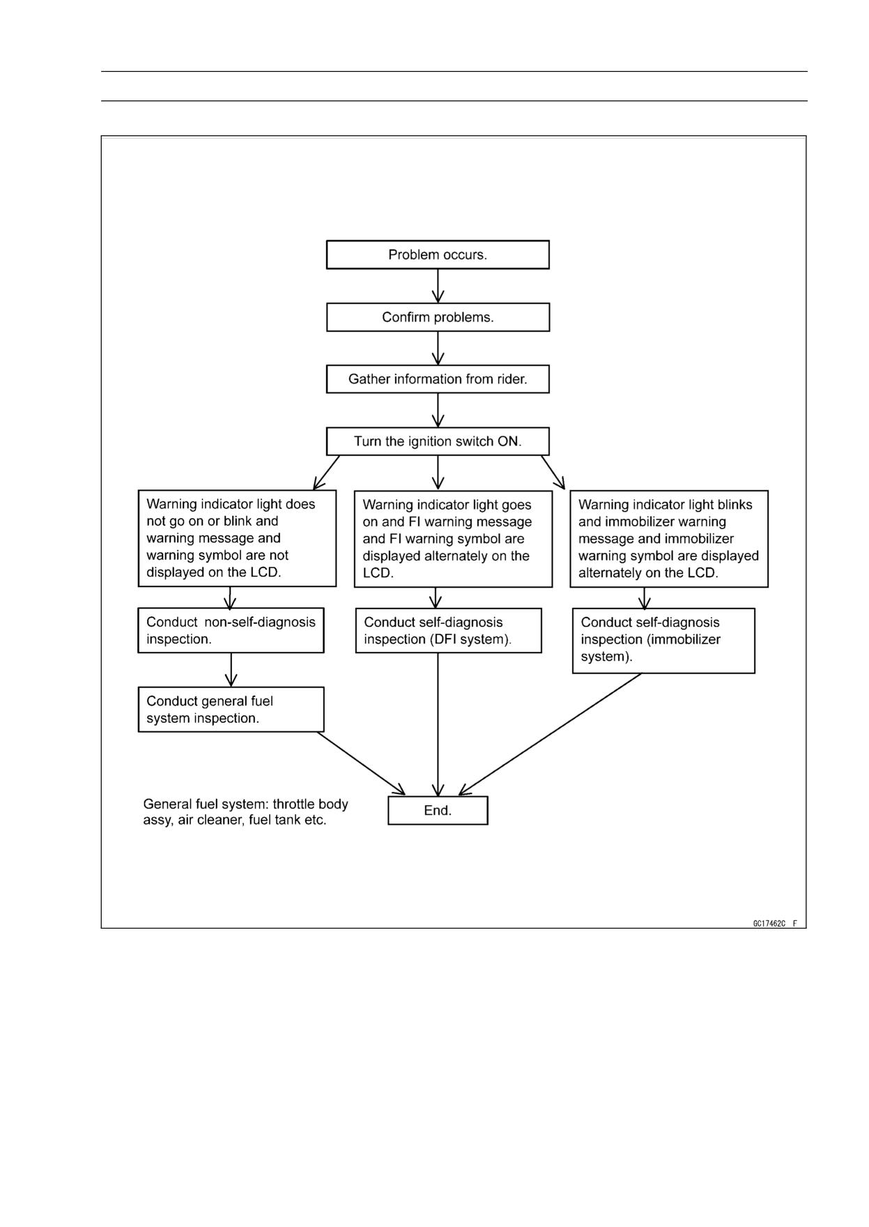
DFI Diagnosis Flow Chart
Inquiries to Rider
○Each rider reacts to problems in different ways, so it is important to confirm what kind of symptoms
the rider has encountered.
○Try to find out exactly what problem occurred under exactly what conditions by asking the rider;
knowing this information may help you reproduce the problem.
○The diagnosis sheet will help prevent you from overlooking any areas, and will help you decide if it
is a DFI system problem, or a general engine problem.
3-30 FUEL SYSTEM (DFI)
Troubleshooting the DFI System
Sample Diagnosis Sheet
Rider name:
Registration No. (license plate No.):
Year of initial registration:
Model:
Engine No.:
Frame No.:
Date problem occurred:
Mileage:
Environment when problem occurred.
Weather
□ fine, □ cloudy, □ rain, □ snow, □ always, □ other:
Temperature
□ hot, □ warm, □ cold, □ very cold, □ always, □ other:
Problem
□ chronic, □ often, □ once
frequency
Road
□ street, □ highway, □ mountain road (□ uphill, □ downhill), □ bumpy, □ pebble
Altitude
□ normal, □ high (about 1000 m or more)
Motorcycle conditions when problem occurred.
Warning
□ Goes on about 3 seconds after from ignition switch ON, and FI warning message
indicator light
and FI warning symbol are displayed alternately on the LCD (DFI system
(LED)
problem).
□ Starts blinking about 3 seconds after from ignition switch ON, and immobilizer
warning message and immobilizer warning symbol are displayed alternately on
the LCD (Immobilizer system problem).
□ Does not go on or blink about 3 seconds after ignition switch ON.
Starting
□ starter motor not rotating.
difficulty
□ starter motor rotating but engine doesn’t turn over.
□ starter motor and engine don’t turn over.
□ no fuel flow (□ no fuel in tank, □ no fuel pump sound).
□ engine flooded (do not crank engine with throttle opened, which promotes engine
flooding).
□ no spark.
□ other:
Engine stalls
□ right after starting.
□ when opening throttle grip.
□ when closing throttle grip.
□ when moving off.
□ when stopping the motorcycle.
□ when cruising.
□ other:
FUEL SYSTEM (DFI) 3-31
Troubleshooting the DFI System
Poor running at low
□ very low idle speed, □ very high idle speed, □ rough idle speed.
speed
□ battery voltage is low (charge the battery).
□ spark plug loose (tighten it).
□ spark plug dirty, broken, or gap maladjusted (remedy it).
□ backfiring.
□ afterfiring.
□ hesitation when acceleration.
□ engine oil viscosity too high.
□ brake dragging.
□ engine overheating.
□ clutch slipping.
□ other:
Poor running or no
□ spark plug loose (tighten it).
power at high speed
□ spark plug dirty, broken, or gap maladjusted (remedy it).
□ spark plug incorrect (replace it).
□ knocking (fuel poor quality or incorrect, → use high-octane gasoline).
□ brake dragging.
□ clutch slipping.
□ engine overheating.
□ engine oil level too high.
□ engine oil viscosity too high.
□ other:
3-32 FUEL SYSTEM (DFI)
DFI System Troubleshooting Guide
NOTE
○This is not an exhaustive list, giving every possible cause for each problem listed. It is meant
simply as a rough guide to assist the troubleshooting for some of the more common difficulties in
DFI system.
○The ECU may be involved in the DFI electrical and ignition system troubles. If these parts and
circuits are checked out good, be sure to check the ECU for ground and power supply. If the
ground and power supply are checked good, replace the ECU.
Engine Won’t Turn Over
Symptoms or possible Causes
Actions (chapter)
Gear position, starter lockout or sidestand switch
Inspect each switch (see chapter 16).
trouble
Immobilizer system trouble
Inspect (see chapter 3).
Vehicle-down sensor coming off
Reinstall (see chapter 3).
Vehicle-down sensor trouble
Inspect (see chapter 3).
Crankshaft sensor trouble
Inspect (see chapter 16).
Stick coil shorted or not in good contact
Inspect or Reinstall (see chapter 16).
Stick coil trouble
Inspect (see chapter 16).
Spark plug dirty, broken or gap maladjusted
Inspect and replace (see chapter 16).
Spark plug incorrect
Replace it with the correct plug (see chapter 2).
ECU ground and power supply trouble
Inspect (see chapter 3).
ECU trouble
Inspect (see chapter 3).
No or little fuel in tank
Supply fuel (see Owner’s Manual).
Fuel Injector trouble
Inspect and replace (see chapter 3).
Fuel pump not operating
Inspect (see chapter 3).
Fuel pump relay trouble
Inspect and replace (see chapter 3).
Fuel filter or pump screen clogged
Inspect and replace fuel pump (see chapter 3).
Fuel pressure regulator trouble
Inspect fuel pressure and replace fuel pump (see
chapter 16).
Fuel line clogged
Inspect and repair (see chapter 3).
Poor Running at Low Speed
Symptoms or Possible Causes
Actions (chapter)
Spark weak:
Stick coil shorted or not in good contact
Inspect or Reinstall (see chapter 16).
Stick coil trouble
Inspect (see chapter 16).
Spark plug dirty, broken or gap maladjusted
Inspect and replace (see chapter 16).
Spark plug incorrect
Replace it with the correct plug (see chapter 2).
ECU trouble
Inspect (see chapter 3).
Fuel/air mixture incorrect:
Little fuel in tank
Supply fuel (see Owner’s Manual).
Air cleaner clogged, poorly sealed, or missing
Clean element or inspect sealing (see chapter 3).
Air duct holder loose
Reinstall (see chapter 3).
Throttle body assy holder loose
Reinstall (see chapter 3).
Throttle body assy dust seal damage
Replace (see chapter 3).
Fuel Injector O-ring damage
Replace (see chapter 3).
Fuel filter or pump screen clogged
Inspect and replace fuel pump (see chapter 3).
FUEL SYSTEM (DFI) 3-33
DFI System Troubleshooting Guide
Symptoms or Possible Causes
Actions (chapter)
Fuel pressure regulator trouble
Inspect fuel pressure and replace fuel pump (see
chapter 16).
Fuel line clogged
Inspect and repair (see chapter 3).
Inlet air pressure sensor trouble
Inspect (see chapter 3).
Atmospheric pressure sensor trouble
Inspect (see chapter 3).
Water temperature sensor trouble
Inspect (see chapter 3).
Inlet air temperature sensor trouble
Inspect (see chapter 3).
Main throttle sensor trouble
Inspect (see chapter 3).
Subthrottle sensor trouble
Inspect (see chapter 3).
Subthrottle valve actuator trouble
Inspect (see chapter 3).
Unstable (rough) idling:
Fuel pressure too low or too high
Inspect (see chapter 3).
Fuel Injector trouble
Inspect (see chapter 3).
Main throttle sensor trouble
Inspect (see chapter 3).
Subthrottle sensor trouble
Inspect (see chapter 3).
Subthrottle valve actuator trouble
Inspect (see chapter 3).
Engine vacuum not synchronizing
Inspect and adjust (see chapter 2).
Inlet air pressure sensor trouble
Inspect (see chapter 3).
Atmospheric pressure sensor trouble
Inspect (see chapter 3).
Water temperature sensor trouble
Inspect (see chapter 3).
Inlet air temperature sensor trouble
Inspect (see chapter 3).
Engine stalls easily:
Spark plug dirty, broken or gap maladjusted
Inspect and replace (see chapter 16).
Stick coil trouble
Inspect (see chapter 16).
Camshaft position sensor trouble
Inspect (see chapter 16).
Main throttle sensor trouble
Inspect (see chapter 3).
Subthrottle sensor trouble
Inspect (see chapter 3).
Subthrottle valve actuator trouble
Inspect (see chapter 3).
Inlet air pressure sensor trouble
Inspect (see chapter 3).
Atmospheric pressure sensor trouble
Inspect (see chapter 3).
Water temperature sensor trouble
Inspect (see chapter 3).
Inlet air temperature sensor trouble
Inspect (see chapter 3).
Fuel pump trouble
Inspect (see chapter 3).
Fuel Injector trouble
Inspect (see chapter 3).
Fuel pressure too low or too high
Inspect (see chapter 3).
Fuel pressure regulator trouble
Inspect fuel pressure and replace fuel pump (see
chapter 16).
Fuel line clogged
Inspect and repair (see chapter 3).
Poor acceleration
Fuel pressure too low
Inspect (see chapter 3).
Water or foreign matter in fuel
Change fuel. Inspect and clean fuel system (see
chapter 3).
Fuel filter or pump screen clogged
Inspect and replace fuel pump (see chapter 3).
Fuel pump trouble
Inspect (see chapter 3).
Fuel Injector trouble
Inspect (see chapter 3).
3-34 FUEL SYSTEM (DFI)
DFI System Troubleshooting Guide
Symptoms or Possible Causes
Actions (chapter)
Main throttle sensor trouble
Inspect (see chapter 3).
Subthrottle sensor trouble
Inspect (see chapter 3).
Subthrottle valve actuator trouble
Inspect (see chapter 3).
Inlet air pressure sensor trouble
Inspect (see chapter 3).
Atmospheric pressure sensor trouble
Inspect (see chapter 3).
Water temperature sensor trouble
Inspect (see chapter 3).
Inlet air temperature sensor trouble
Inspect (see chapter 3).
Spark plug dirty, broken or gap maladjusted
Inspect and replace (see chapter 16).
Stick coil trouble
Inspect (see chapter 16).
Stumble:
Fuel pressure too low
Inspect (see chapter 3).
Fuel Injector trouble
Inspect (see chapter 3).
Main throttle sensor trouble
Inspect (see chapter 3).
Subthrottle sensor trouble
Inspect (see chapter 3).
Subthrottle valve actuator trouble
Inspect (see chapter 3).
Inlet air pressure sensor trouble
Inspect (see chapter 3).
Atmospheric pressure sensor trouble
Inspect (see chapter 3).
Water temperature sensor trouble
Inspect (see chapter 3).
Inlet air temperature sensor trouble
Inspect (see chapter 3).
Surge:
Unstable fuel pressure
Fuel pressure regulator trouble (Inspect and
replace fuel pump) or kinked fuel line Inspect
(Inspect and replace fuel pump) (see chapter 3).
Fuel Injector trouble
Inspect (see chapter 3).
Water temperature sensor trouble
Inspect (see chapter 3).
Backfiring when deceleration:
Spark plug dirty, broken or gap maladjusted
Inspect and replace (see chapter 16).
Fuel pressure too low
Inspect (see chapter 3).
Fuel pump trouble
Inspect (see chapter 3).
Main throttle sensor trouble
Inspect (see chapter 3).
Subthrottle sensor trouble
Inspect (see chapter 3).
Subthrottle valve actuator trouble
Inspect (see chapter 3).
Inlet air pressure sensor trouble
Inspect (see chapter 3).
Atmospheric pressure sensor trouble
Inspect (see chapter 3).
Water temperature sensor trouble
Inspect (see chapter 3).
Inlet air temperature sensor trouble
Inspect (see chapter 3).
Air switching valve trouble
Inspect and replace (see chapter 16).
Air suction valve trouble
Inspect and replace (see chapter 5).
After fire:
Spark plug burned or gap maladjusted
Replace (see chapter 16).
Fuel Injector trouble
Inspect (see chapter 3).
Inlet air pressure sensor trouble
Inspect (see chapter 3).
Atmospheric pressure sensor trouble
Inspect (see chapter 3).
Water temperature sensor trouble
Inspect (see chapter 3).
FUEL SYSTEM (DFI) 3-35
DFI System Troubleshooting Guide
Symptoms or Possible Causes
Actions (chapter)
Inlet air temperature sensor trouble
Inspect (see chapter 3).
Other:
Intermittent any DFI fault and its recovery
Check that DFI connectors are clean and tight,
and examine leads for signs of burning or fraying
(see chapter 3).
Poor Running or No Power at High Speed:
Symptoms or Possible Causes
Actions (chapter)
Firing incorrect:
Stick coil shorted or not in good contact
Inspect or Reinstall (see chapter 16).
Stick coil trouble
Inspect (see chapter 16).
Spark plug dirty, broken or gap maladjusted
Inspect and replace (see chapter 16).
Spark plug incorrect
Replace it with the correct plug (see chapter 2).
ECU trouble
Inspect (see chapter 3).
Fuel/air mixture incorrect:
Air cleaner clogged, poorly sealed, or missing
Clean element or inspect sealing (see chapter 3).
Air duct holder loose
Reinstall (see chapter 3).
Throttle body assy holder loose
Reinstall (see chapter 3).
Throttle body assy dust seal damage
Replace (see chapter 3).
Water or foreign matter in fuel
Change fuel. Inspect and clean fuel system (see
chapter 3).
Fuel Injector O-ring damage
Visually inspect and replace (see chapter 3).
Fuel Injector clogged
Inspect and repair (see chapter 3).
Fuel line clogged
Inspect and repair (see chapter 3).
Fuel pump operates intermittently and often DFI
Fuel Pump bearings may wear. Replace the fuel
fuse blows.
pump (see chapter 3).
Fuel pump trouble
Inspect (see chapter 3).
Inlet air pressure sensor trouble
Inspect (see chapter 3).
Cracked or obstructed inlet air pressure sensor
Inspect and repair or replace (see chapter 3).
hose
Atmospheric pressure sensor trouble
Inspect (see chapter 3).
Water temperature sensor trouble
Inspect (see chapter 3).
Inlet air temperature sensor trouble
Inspect (see chapter 3).
Main throttle sensor trouble
Inspect (see chapter 3).
Subthrottle sensor trouble
Inspect (see chapter 3).
Subthrottle valve actuator trouble
Inspect (see chapter 3).
Knocking:
Fuel poor quality or incorrect
Fuel chage (Use the gasoline recommended in
the Owner’s Manual).
Spark plug incorrect
Replace it with the correct plug (see chapter 2).
Stick coil trouble
Inspect (see chapter 16).
ECU trouble
Inspect (see chapter 3).
Engine vacumm not synchronizing
Inspect and adjust (see chapter 2).
Inlet air pressure sensor trouble
Inspect (see chapter 3).
Atmospheric pressure sensor trouble
Inspect (see chapter 3).
3-36 FUEL SYSTEM (DFI)
DFI System Troubleshooting Guide
Symptoms or Possible Causes
Actions (chapter)
Water temperature sensor trouble
Inspect (see chapter 3).
Inlet air temperature sensor trouble
Inspect (see chapter 3).
Miscellaneous:
Subthrottle sensor trouble
Inspect (see chapter 3).
Subthrottle valve actuator trouble
Inspect (see chapter 3).
Speed sensor trouble
Inspect (see chapter 3).
Throttle valves will not fully open
Inspect throttle cables and lever linkage (see
chapter 3).
Engine overheating - Water temperature sensor ,
(see Overheating of Troubleshooting Guide in
crankshaft sensor or speed sensor trouble
chapter 17).
Air switching valve trouble
Inspect and replace (see chapter 16).
Air suction valve trouble
Inspect and replace (see chapter 5).
Exhaust Smokes Excessively:
(White smokes)
Air cleaner clogged
Clean element (see chapter 3).
Fuel pressure too high
Inspect (see chapter 3).
Fuel Injector trouble
Inspect (see chapter 3).
Water temperature sensor trouble
Inspect (see chapter 3).
Inlet air temperature sensor trouble
Inspect (see chapter 3).
(Brown smoke)
Air duct holder loose
Reinstall (see chapter 3).
Fuel pressure too low
Inspect (see chapter 3).
Water temperature sensor trouble
Inspect (see chapter 3).
Inlet air temperature sensor trouble
Inspect (see chapter 3).
FUEL SYSTEM (DFI) 3-37
Self-Diagnosis
Self-diagnosis Outline
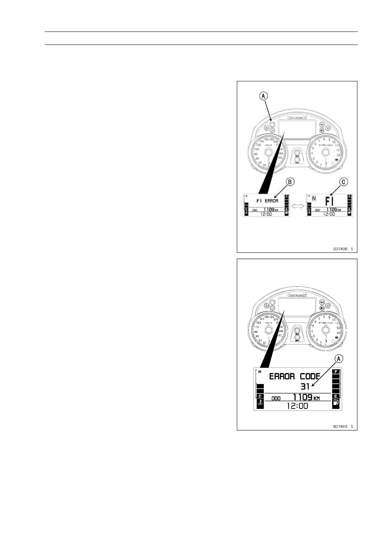
The self-diagnosis system has two modes and can be
switched to another mode by operating the meter unit.
User Mode
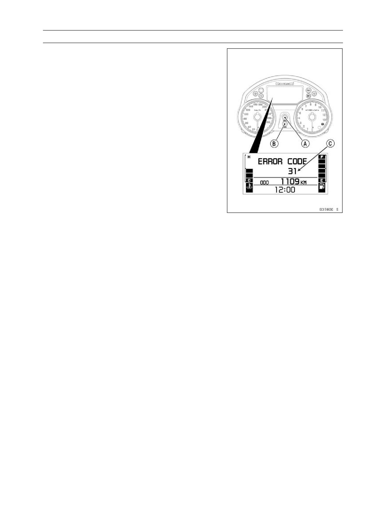
The ECU notifies the rider of troubles in DFI system , igni-
tion system and immobilizer system by lighting up or blink-
ing the warning indicator light (LED) [A] and displaying the
warning message [B] and warning symbol [C] alternately
on the LCD (Liquid Crystal Display) when DFI, ignition and
immobilizer system parts are faulty, and initiates fail-safe
function. In case of serious troubles ECU stops the injec-
tion/ignition/starter motor operation.
Dealer Mode
The LCD (Liquid Crystal Display) display the service
code(s) [A] to show the problem(s) which the DFI system,
ignition system and immobilizer system has at the moment
of diagnosis.
3-38 FUEL SYSTEM (DFI)
Self-Diagnosis
Self-diagnosis Procedures
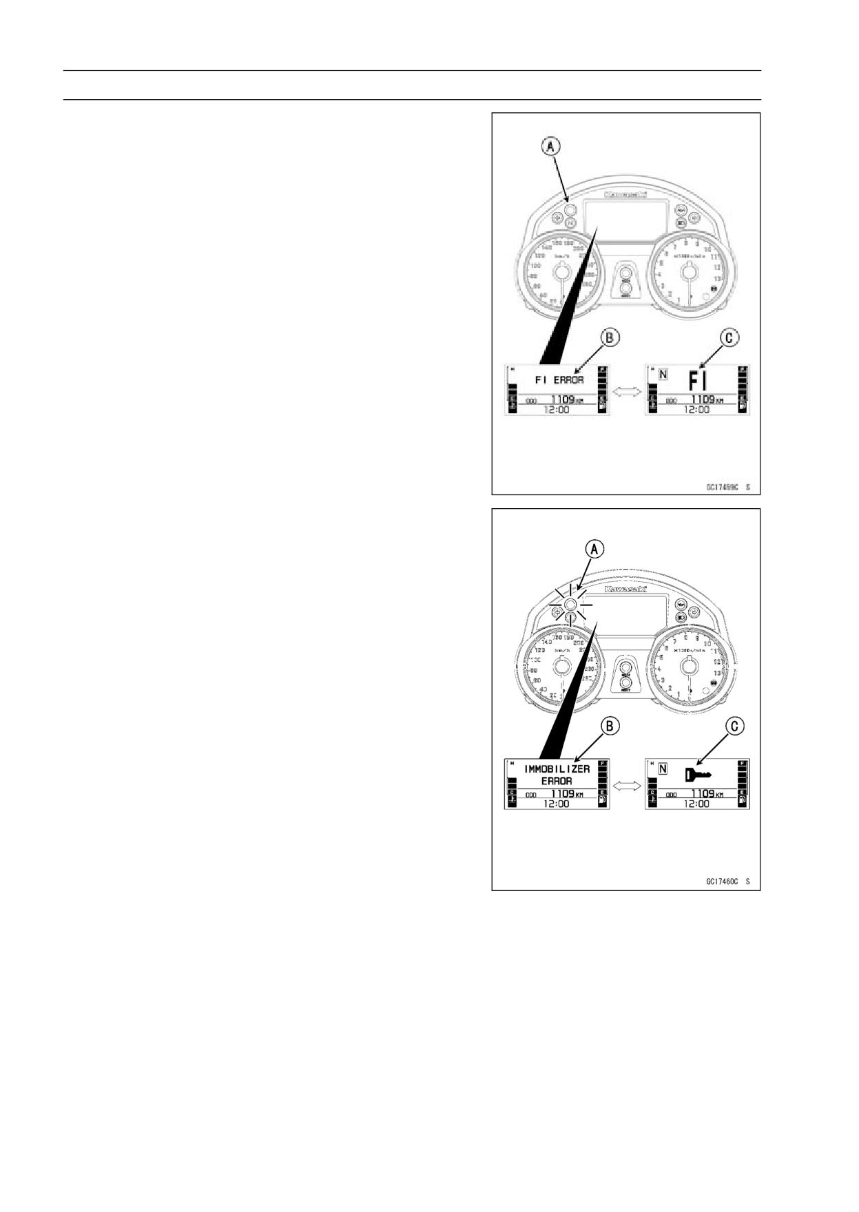
○When a problem occurs with DFI system and ignition sys-
tem, the warning indicator (LED) [A] goes on and FI warn-
ing message [B] and FI warning symbol [C] are displayed
alternately on the LCD (Liquid Crystal Display) to alert the
rider.
○For models equipped with an immobilizer system, the
warning indicator light (LED) [A] blinks and immobilizer
warning message [B] and immobilizer warning symbol
[C] are alternately displayed on the LCD, when a problem
occurs in the system.
FUEL SYSTEM (DFI) 3-39
Self-Diagnosis
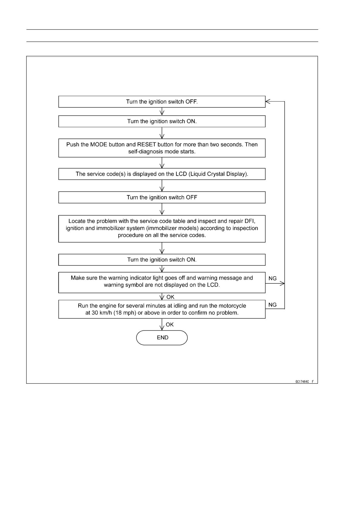
• Turn the ignition switch ON.
• Push the MODE button [A] and RESET button [B] for more
than two seconds.
• The service code [C] is displayed on the LCD by the num-
ber of two digits.
○When pushing and holding the MODE button while the
warning massage and warning symbol are displayed al-
ternately on the LCD, the display on the LCD is shifted to
the previous display with the warning indicator light (LED)
goes on.
○After switching to the previous display, the service code
can not be displayed even if pushing the MODE button
and RESET button for more than two seconds.
• Any of the following procedures ends self-diagnosis.
○When the service code is displayed on the LCD, push
the MODE button and RESET button for more than two
seconds.
○When the ignition switch is turned OFF.
3-40 FUEL SYSTEM (DFI)
Self-Diagnosis
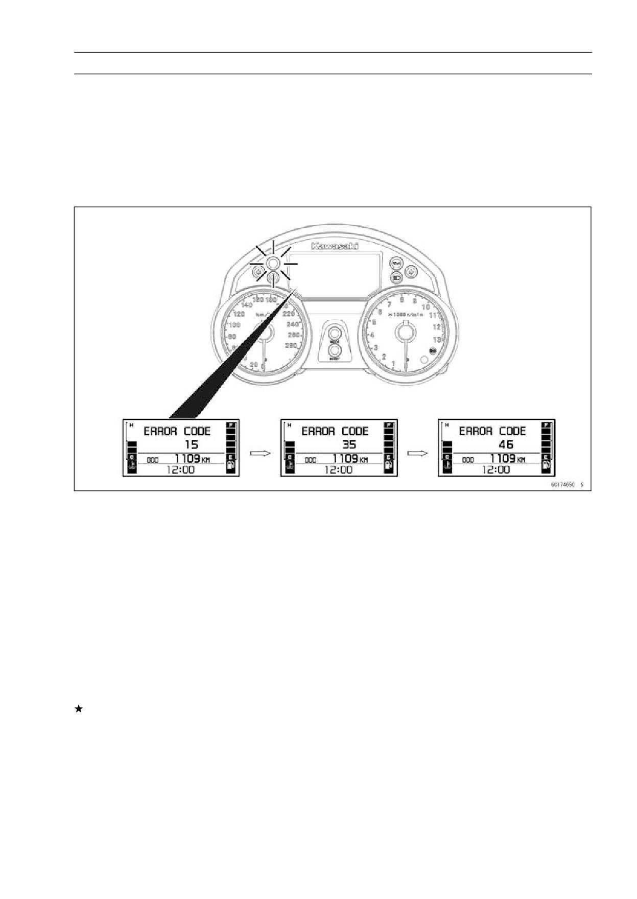
Self-Diagnosis Flow Chart
FUEL SYSTEM (DFI) 3-41
Self-Diagnosis
Service Code Reading
○The service code(s) is displayed on the LCD by the number of two digits.
○When there are a number of problems, all the service codes can be stored and the display will begin
starting from the lowest number service code in the numerical order.
○Then after completing all codes, the display is repeated until the ignition switch is turned OFF or
MODE button and RESET button are pushed for more than two seconds.
○For example, if three problems occurred in the order of 46, 15, 35, the service codes are
displayed (each two seconds) from the lowest number in the order listed as shown below.
(15→35→46)→(15→35→46)→· · ·(repeated)
○In the case more than two service codes are available, you may push the MODE button to shift into
the other code too.
○If the no problem or when the repair has done, warning indicator light (LED) goes off and warning
message and warning symbol are not displayed, and no service code is displayed.
○If the problem is with the following parts, the ECU can not memorize these problem, he warning
indicator light (LED) do not lights up or blinks and warning message and warning symbol are not
displayed, and no service codes can be displayed.
Warning Indicator Light (LED)
Meter Panel LCD
Stick Coil Secondary Wiring and Ground Wiring (see Stick Coil (Ignition Coil together with Spark
Plug Cap) Inspection in the Electrical System chapter)
ECU Power Source Wiring and Ground Wiring (see ECU power Supply Inspection)
Service Code Erasing
○When repair has been done, warning indicator light (LED) goes off and warning message and warn-
ing symbol are not displayed, and no service code is displayed.
But the service codes stored in memory of the ECU are not erased to preserve the problem history.
In this model, the problem history can not be erased.
3-42 FUEL SYSTEM (DFI)
Self-Diagnosis
Service Code Table
Service Code
Problems
11
Main throttle sensor malfunction, wiring open or short
12
Inlet air pressure sensor malfunction, wiring open or short
13
Inlet air temperature sensor malfunction, wiring open or short
14
Water temperature sensor malfunction, wiring open or short
15
Atmospheric pressure sensor malfunction, wiring open or short
21
Crankshaft sensor malfunction, wiring open or short
23
Camshaft position sensor malfunction, wiring open or short
24
Speed sensor malfunction
25
Gear position switch malfunction, wiring open or short
31
Vehicle-down sensor malfunction, wiring open or short
32
Subthrottle sensor malfunction, wiring open or short
35
Immobilizer amplifier malfunction
36
Blank key detection
46
Fuel pump relay malfunction, relay is stuck
51
Stick (Ignition) coil #1 malfunction, wiring open or short
52
Stick (Ignition) coil #2 malfunction, wiring open or short
53
Stick (Ignition) coil #3 malfunction, wiring open or short
54
Stick (Ignition) coil #4 malfunction, wiring open or short
62
Subthrottle valve actuator malfunction, wiring open or short
75
ECU main relay malfunction, relay is stuck
Notes:
○The ECU may be involved in these problems. If all the parts and circuits checked out good, be sure
to check the ECU for ground and power supply. If the ground and power supply are checked good,
replace the ECU.
○When no service code is displayed, the electrical parts of the DFI system has no fault, and the
mechanical parts of the DFI system and the engine are suspect.
FUEL SYSTEM (DFI) 3-43
Self-Diagnosis
Backups
○The ECU takes the following measures to prevent engine damage when the DFI, ignition or immo-
bilizer system parts have troubles.
Service
Output Signal Usable
Parts
Backups by ECU
Codes
Range or Criteria
If the main throttle sensor system fails (the
Main Throttle Sensor
signal is out of the usable range, wiring short
Main Throttle
11
Output Voltage
or open), the ECU locks ignition timing into the
Sensor
0.2 ∼ 4.8 V
ignition timing at closed throttle position and
sets the DFI in the D-J method.
Inlet Air Pressure
If the inlet air pressure sensor system fails (the
Inlet Air
(absolute)
signal Pv is out of the usable range, wiring
12
Pressure
Pv = 100 mmHg ∼ 900
short or open), the ECU sets the DFI in the
Sensor
mmHg
α-N method (1).
Inlet Air
If the inlet air temperature sensor fails (the
Inlet Air Temperature
13
Temperature
signal is out of the usable range, wiring short
Ta = - 30°C ∼ + 100°C
Sensor
or open), the ECU sets Ta at 30°C.
Water
If the water temperature sensor system fails
Water Temperature
14
Temperature
(the signal is out of the usable range, wiring
Tw = - 30°C° ∼ + 120°C
Sensor
short or open), the ECU sets Tw at 80°C.
Absolute Atmospheric
If the atmospheric pressure sensor system
Atmospheric
Pressure
fails (the signal is out of the usable range,
15
Pressure
Pa = 100 mmHg ∼ 900
wiring short or open), the ECU sets Pa at 760
Sensor
mmHg
mmHg (the standard atmospheric pressure).
Crankshaft sensor cannot
Crankshaft
If crankshaft sensor fails, the engine stops by
21
send the signal to the ECU
Sensor
itself.
during 8 crankings.
Camshaft position sensor
If the camshaft position sensor system fails
Camshaft
cannot send the signal
(the signal is missing, wiring short or open),
23
Position
to the ECU during 24
the ECU continues to ignite cylinders in the
Sensor
crankings.
same sequence following the last good signal.
Speed sensor must send
If the speed sensor system fails (no signal,
Speed
4 signals (output signal) to
24
wiring short or open), the speedometer shows
Sensor
the ECU at the one rotation
0.
of the drive shaft.
Gear
Gear Position Switch
If the speed sensor system fails (no signal,
25
Position
Output Voltage (signal)
wiring short or open), the ECU set the top (6)
Switch
Vg = 0.2 ∼ 4.8 V
gear position.
If the vehicle-down sensor system has failures
Vehicle
Vehicle-down Sensor
(the output voltage Vd is more than usable
31
-down
Output Voltage (signal)
range, wiring open), the ECU shuts off the
Sensor
Vd = 0.2 ∼ 4.8 V
fuel pump, the fuel injectors and the ignition
system.
If the subthrottle sensor system fails (the
Subthrottle Sensor Output
Subthrottle
signal is out of the usable range, wiring short
32
Voltage
Sensor
or open), the actuator locks subthrottle valve
0.2 ∼ 4.8 V
at full open position.
Immobilizer
If the immobilizer system fails (no signal, wiring
35
-
Amplifier
short or open), the vehicle is no start and run.
Master or
The user or master key
If the blank key or broken key is used, the
36
User Key
must use register key.
vehicle is no start and run.
3-44 FUEL SYSTEM (DFI)
Self-Diagnosis
Service
Output Signal Usable
Parts
Backups by ECU
Codes
Range or Criteria
When the relay ON
Fuel Pump
46
condition, battery monitor
If the relay fails, battery monitor voltage 12 V.
Relay
voltage 5 V or more
The ignition coil primary
If the ignition primary winding #1 has failures
Stick Coil
winding must send signals
(no signal, wiring short or open), the ECU
51
#1 (Ignition
(output voltage) 32 or more
shuts off the injector #1 to stop fuel to the
Coil)*
times continuously to the
cylinder #1, though the engine keeps running.
ECU.
The ignition coil primary
If the ignition primary winding #2 has failures
Stick Coil
winding must send signals
(no signal, wiring short or open), the ECU
52
#2 (Ignition
(output voltage) 32 or more
shuts off the injector #2 to stop fuel to the
Coil)*
times continuously to the
cylinder #2, though the engine keeps running.
ECU.
The ignition coil primary
If the ignition primary winding #3 has failures
Stick Coil
winding must send signals
(no signal, wiring short or open), the ECU
53
#3 (Ignition
(output voltage) 32 or more
shuts off the injector #3 to stop fuel to the
Coil)*
times continuously to the
cylinder #3, though the engine keeps running.
ECU.
The ignition coil primary
If the ignition primary winding #4 has failures
Stick Coil
winding must send signals
(no signal, wiring short or open), the ECU
54
#4 (Ignition
(output voltage) 32 or more
shuts off the injector #4 to stop fuel to the
Coil)*
times continuously to the
cylinder #4, though the engine keeps running.
ECU.
The actuator operates
If the subthrottle valve actuator fails (the
Subthrottle
open and close of the
signal is out to the usable range, wiring short
62
Valve
subthrottle valve by the
or open), the ECU stops the current to the
Actuator
pulse signal from the ECU.
actuator.
When the relay OFF
ECU Main
75
condition, the main relay is
-
Relay
open.
Note:
(1) α-N Method: the DFI control method from medium to heavy engine load. When the engine load
is light like at idling or low speed, the ECU determines the injection quantity by calculating from the
throttle vacuum (vacuum sensor output voltage) and engine speed (crankshaft sensor output voltage).
This method is called D-J method. As the engine speed increases, and the engine load turns middle
to heavy, the ECU determines the injection quantity by calculating from the throttle opening (throttle
sensor output voltage) and the engine speed. This method is called α-N method.
* This depends on the number of stopped cylinders.
FUEL SYSTEM (DFI) 3-45
Main Throttle Sensor (Service Code 11)
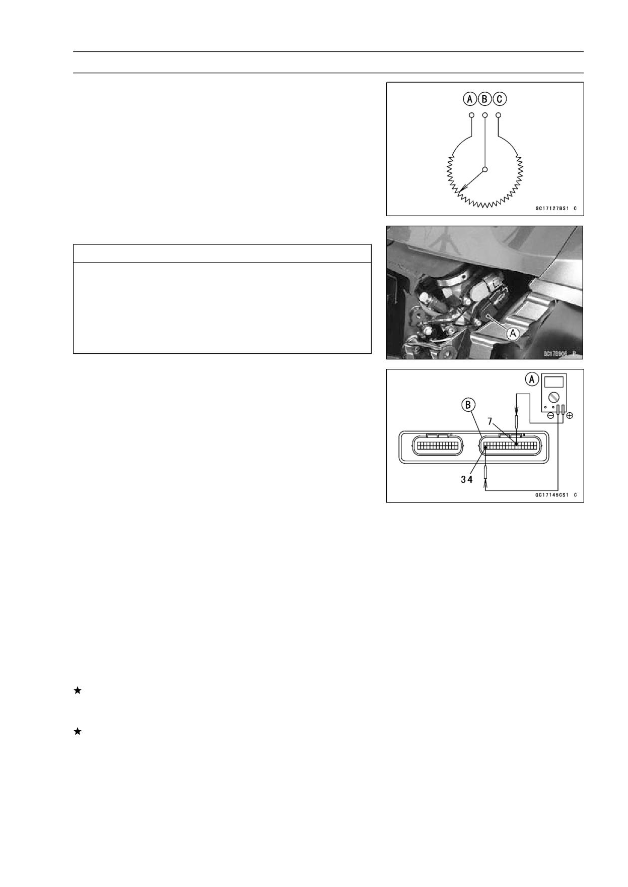
The main throttle sensor is a rotating variable resistor that
change output voltage according to throttle operating. The
ECU senses this voltage change and determines fuel injec-
tion quantity, and ignition timing according to engine rpm,
and throttle opening.
Input Terminal [A]
Output Terminal [B]
Ground Terminal [C]
Main Throttle Sensor Removal/Adjustment
CAUTION
Do not remove or adjust the main throttle sensor [A]
since it has been adjusted and set with precision at
the factory.
Never drop the throttle body assy, especially on a
hard surface. Such a shock to the sensor can dam-
age it.
Input Voltage Inspection
NOTE
○Be sure the battery is fully charged.
• Turn the ignition switch OFF.
• Remove the ECU (see ECU Removal).
○Do not disconnect the ECU connectors.
• Connect a digital meter [A] to the connectors [B], using
the needle adapter set.
Special Tool - Needle Adapter Set: 57001-1457
Main Throttle Sensor Input Voltage
Connections to ECU Connector
Meter (+) → BL lead (terminal 7)
Meter (-) → BR/BK lead (terminal 34)
• Measure the input voltage with the engine stopped, and
with the connectors joined.
• Turn the ignition switch ON.
Input Voltage at ECU Connector
Standard: DC 4.75 ∼ 5.25 V
• Turn the ignition switch OFF.
If the reading of input voltage is less than the standard,
check the ECU for its ground, and power supply (see ECU
Power Supply Inspection) and wiring shorted.
If the input voltage is within the standard range, check the
input voltage at the main throttle sensor connector.
3-46 FUEL SYSTEM (DFI)
Main Throttle Sensor (Service Code 11)
• Remove the right fairing cover (see Fairing Cover Re-
moval in the Frame chapter).
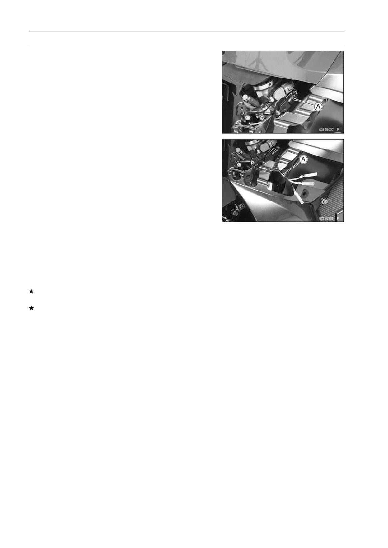
• Disconnect the main throttle sensor connector [A].
• Connect the harness adapter [A] between the harness
connector and main throttle sensor connector.
Special Tool - Throttle Sensor Setting Adapter:
57001
-1538
• Connect a digital meter to the harness adapter leads.
Main Throttle Sensor Input Voltage
Connections to Adapter
Meter (+)→ W (sensor BL) lead
Meter (-)→ BK (sensor BR/BK) lead
• Measure the input voltage with the engine stopped, and
with the connector joined.
• Turn the ignition switch ON.
Input Voltage at Sensor
Standard: DC 4.75 ∼ 5.25 V
• Turn the ignition switch OFF.
If the reading is out of the range, check the wiring (see
wiring diagram in this section).
If the reading is good, check the output voltage of the
sensor.
FUEL SYSTEM (DFI) 3-47
Main Throttle Sensor (Service Code 11)
Output Voltage Inspection
• Measure the output voltage at the ECU in the same way
as input voltage inspection. Note the following.
Digital Meter [A]
Connector [B]
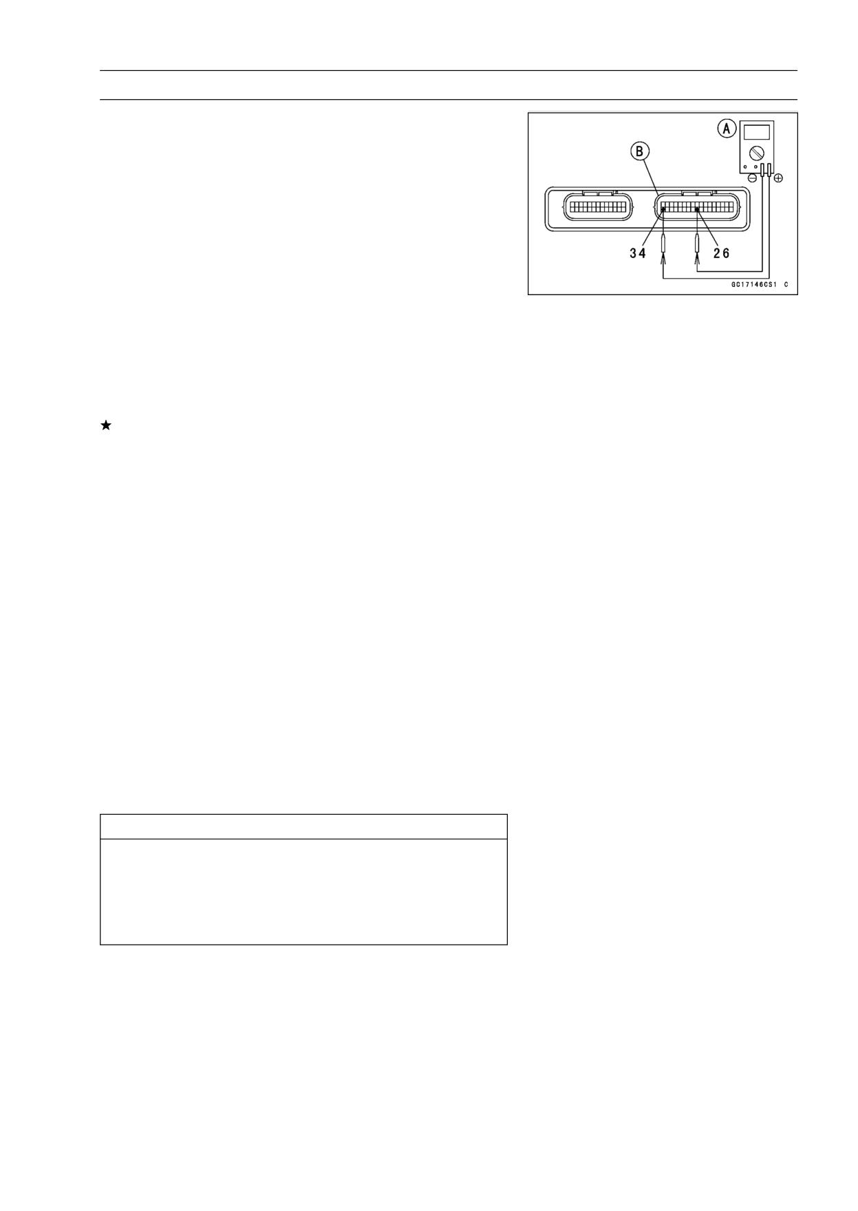
Special Tool - Needle Adapter Set: 57001-1457
Main Throttle Sensor Output Voltage
Connections to ECU Connector
Meter (+) → Y/W lead (terminal 26)
Meter (-) → BR/BK lead (terminal 34)
• Start the engine and warm it up thoroughly.
• Check idle speed to ensure throttle opening is correct.
Idle Speed
Standard:
1 100 r/min (rpm)
If the idle speed is out of the specified range, adjust the
idle speed (see Idle Speed Inspection in Periodic Mainte-
nance chapter).
• Turn the ignition switch OFF.
• Measure the output voltage with the engine stopped, and
with the connector joined.
• Turn the ignition switch ON.
• Measure the output voltage when the throttle is fully
opened or completely closed.
Output Voltage at ECU
Standard: DC 0.63 ∼ 3.91 V (at idle throttle opening to
full throttle opening)
NOTE
○The throttle sensor is operating correctly if the following
voltages are obtained:
• DC 0.63 V (or slightly higher) with the throttle at the
idle position.
• DC 3.91 V (or slightly lower) with the throttle at the fully
open position.
CAUTION
Do not remove or adjust the main throttle sensor.
It has been adjusted and set with precision at the
factory.
Never drop the sensor can especially on a hard sur-
face. A shock to the sensor can damage it.
3-48 FUEL SYSTEM (DFI)
Main Throttle Sensor (Service Code 11)
NOTE
○The standard voltage refers to the value when the volt-
age reading at the Input Voltage Inspection shows 5V
exactly.
○When the input voltage reading shows other than 5V,
derive a voltage range as follows.
Example:
In the case of a input voltage of 4.75 V.
0.63 × 4.75 ÷ 5.00 = 0.60 V
3.91 × 4.75 ÷ 5.00 = 3.71 V
Thus, the valid range is 0.60 ∼ 3.71 V
If the output voltage is within the standard range, check
the ECU for its ground, and power supply (see ECU
Power Supply Inspection).
If the ground and power supply are good, replace the ECU
(see ECU section).
If the output voltage is far out of the standard range (e.g.
when the wiring is open, the reading is 0 V), check the
output voltage again at the sensor connector.
FUEL SYSTEM (DFI) 3-49
Main Throttle Sensor (Service Code 11)
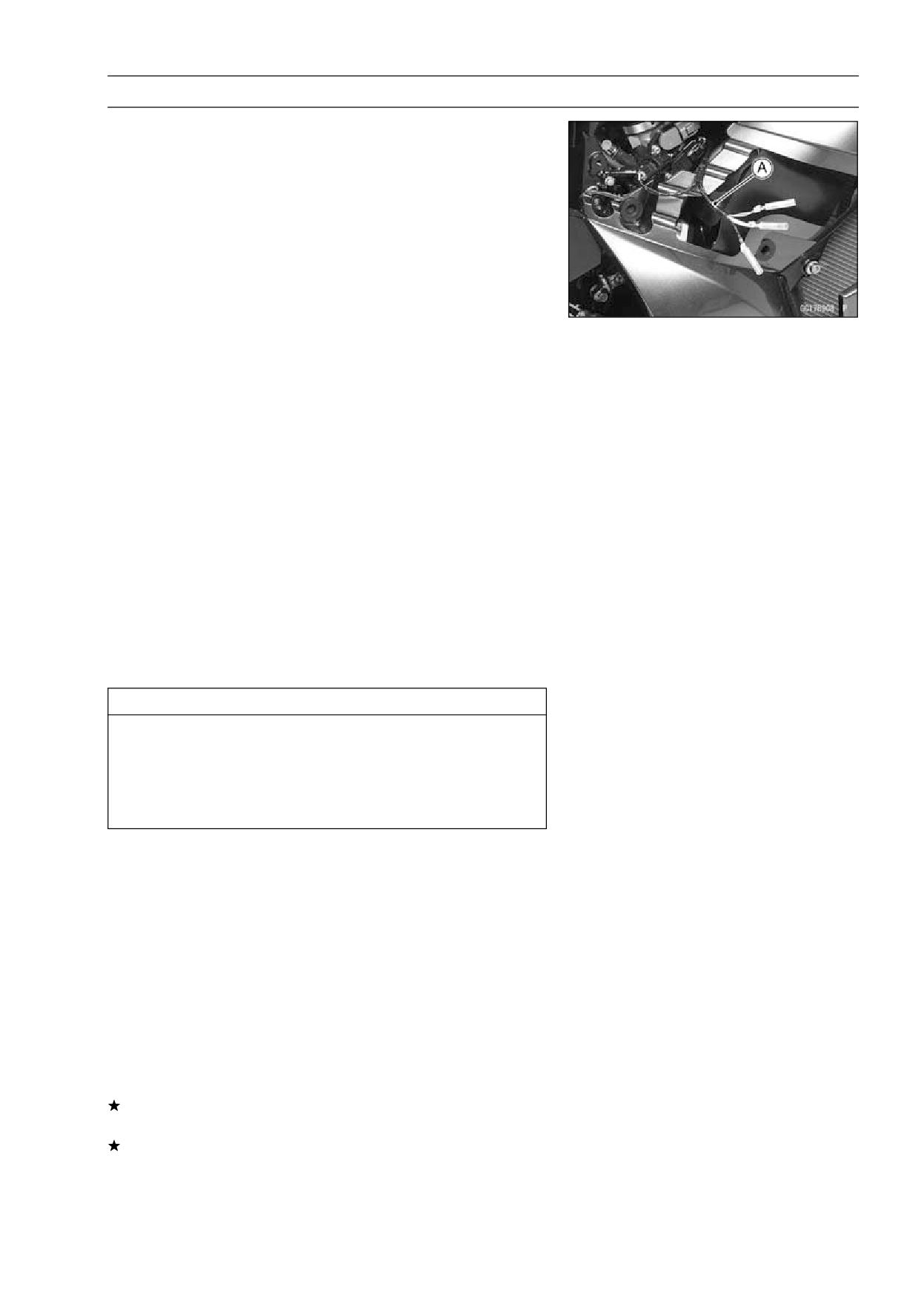
• Disconnect the main throttle sensor connector and con-
nect the harness adapter [A] between the harness con-
nector and main throttle sensor connector.
Special Tool - Throttle Sensor Setting Adapter:
57001
-1538
• Connect a digital meter to the harness adapter leads.
Throttle Sensor Output Voltage
Connections to Adapter
Meter (+) → R (sensor Y/W) lead
Meter (-) → BK (sensor BR/BK) lead
• Measure the sensor output voltage with the engine
stopped, and with the connector joined.
• Turn the ignition switch ON.
• Measure the output voltage when the throttle is fully
opened or completely closed.
Output Voltage at Sensor
Standard: DC 0.63 ∼ 3.91 V (at idle throttle opening to
full throttle opening)
NOTE
○The throttle sensor is operating correctly if the following
voltages are obtained:
• DC 0.63 V (or slightly higher) with the throttle at the
idle position.
• DC 3.91 V (or slightly lower) with the throttle at the fully
open position.
CAUTION
Do not remove or adjust the main throttle sensor.
It has been adjusted and set with precision at the
factory.
Never drop the sensor, especially on a hard surface.
A shock to the sensor can damage it.
NOTE
○The standard voltage refers to the value when the volt-
age reading at the Input Voltage Inspection shows 5V
exactly.
○When the input voltage reading shows other than 5V,
derive a voltage range as follows.
Example:
In the case of a input voltage of 4.75 V.
0.63 × 4.75 ÷ 5.00 = 0.60 V
3.91 × 4.75 ÷ 5.00 = 3.71 V
Thus, the valid range is 0.60 ∼ 3.71 V
• Turn the ignition switch OFF.
If the reading is out of the standard range, inspect the
main throttle sensor resistance.
If the output voltage is normal, check the wiring for conti-
nuity (see wiring diagram in this section).
3-50 FUEL SYSTEM (DFI)
Main Throttle Sensor (Service Code 11)
Resistance Inspection
• Turn the ignition switch OFF.
• Disconnect the main throttle sensor connector.
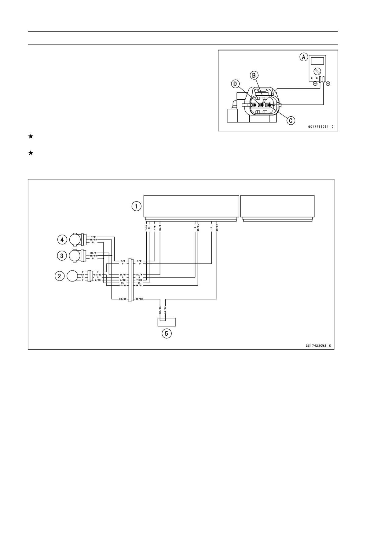
• Connect a digital meter [A] to the main throttle sensor
connector [B].
• Measure the main throttle sensor resistance.
Main Throttle Sensor Resistance
Connections: BL lead [C] ←→BR/BK lead [D]
Standard:
4 ∼ 6 kΩ
If the reading is out of the range, replace the throttle body
assy (see Throttle Body Assy section).
If the reading is within the range, but the problem still
exists, replace the ECU (see ECU section).
Main Throttle Sensor Circuit
1. ECU
2. Subthrottle Valve Actuator
3. Subthrottle Sensor
4. Main Throttle Sensor
5. Water-proof Joint 2
FUEL SYSTEM (DFI) 3-51
Inlet Air Pressure Sensor (Service Code 12)
CAUTION
Never drop the sensor, especially on a hard surface.
Such a shock to the part can damage it.
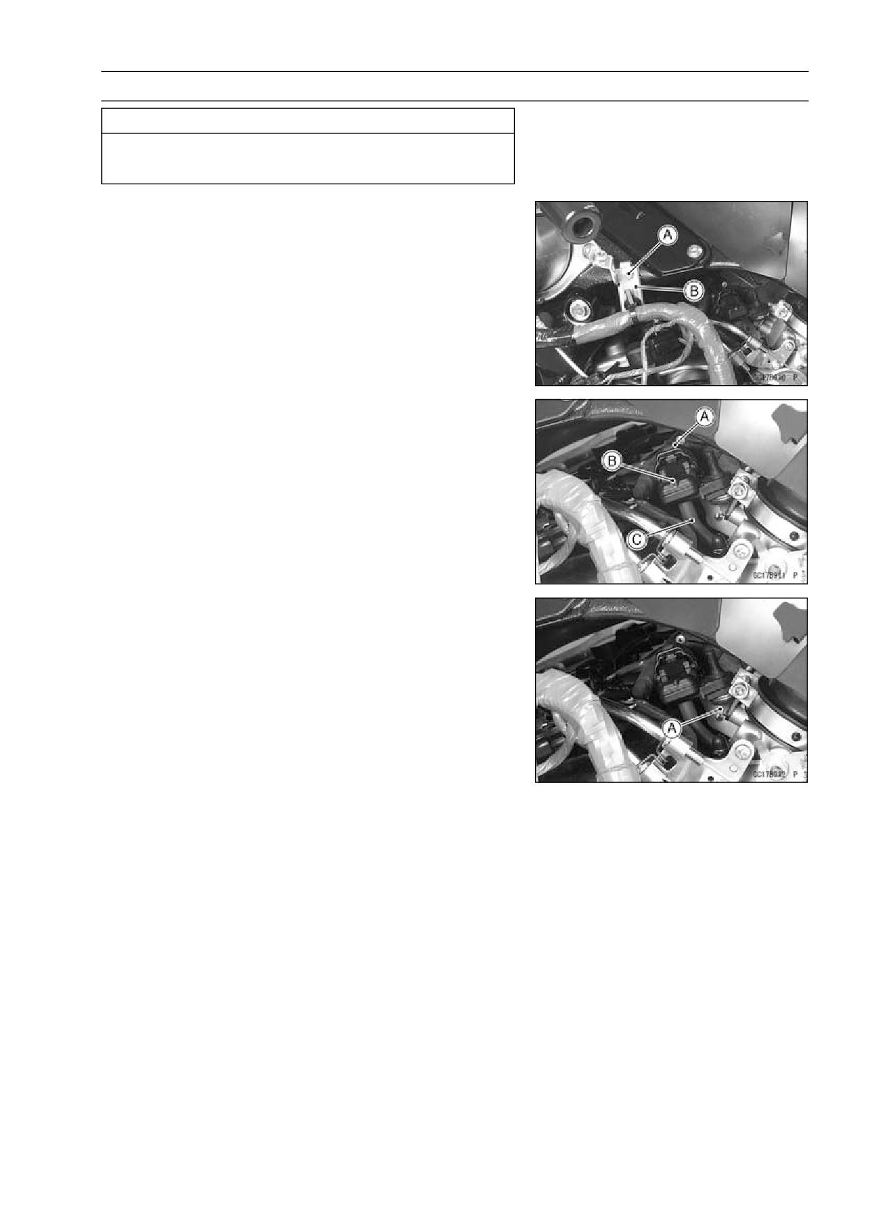
Removal
• Remove:
Fuel Tank Cover (see Fuel Tank Removal)
Bolt [A]
Bracket [B]
• Remove:
Inlet Air Pressure Sensor Connector [A]
Inlet Air Pressure Sensor [B]
Vacuum Hose [C]
Installation
NOTE
○The inlet air pressure sensor is the same part as the at-
mospheric sensor except that the sensor has a vacuum
hose and different wiring.
• Install the vacuum hose.
• Put the inlet air pressure sensor in the stay plate [A] of
throttle body assy.
3-52 FUEL SYSTEM (DFI)
Inlet Air Pressure Sensor (Service Code 12)
Input Voltage Inspection
NOTE
○Be sure the battery is fully charged.
○The inspection is the same as “Input Voltage Inspection”
of the throttle sensor and the atmospheric pressure sen-
sor.
• Turn the ignition switch OFF.
• Remove the ECU (see ECU Removal).
○Do not disconnect the ECU connectors.
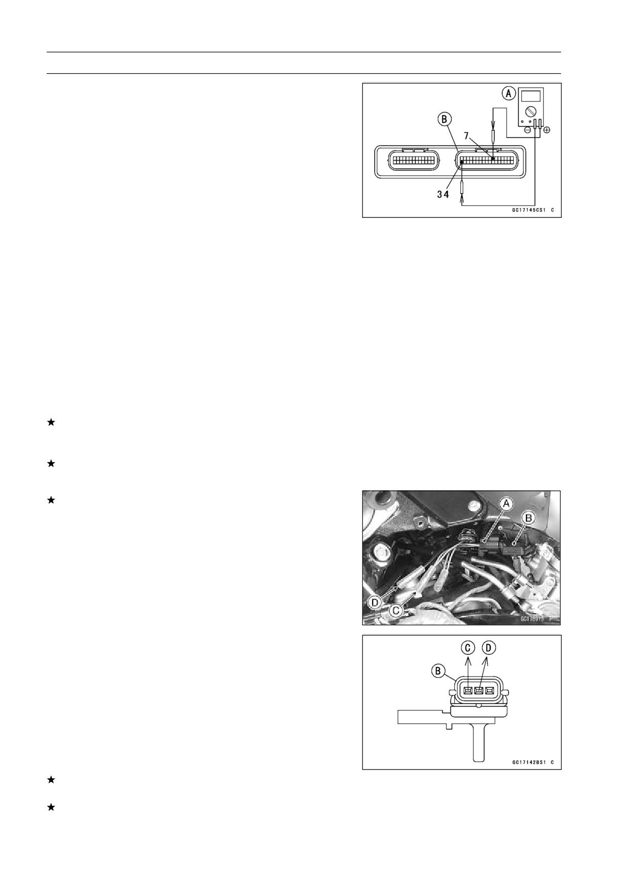
• Connect a digital meter [A] to the connector [B], with the
needle adapter set.
Special Tool - Needle Adapter Set: 57001-1457
Inlet Air Pressure Sensor Input Voltage
Connections to ECU Connector
Meter (+) → BL lead (terminal 7)
Meter (-) → BR/BK lead (terminal 34)
• Measure the input voltage with the engine stopped, and
with the connectors joined.
• Turn the ignition switch ON.
Input Voltage at ECU
Standard: DC 4.75 ∼ 5.25 V
If the reading is less than the standard range, check the
ECU for its ground, and power supply (see ECU Power
Supply Inspection).
If the ground and power supply are good, replace the ECU
(see ECU section).
If the reading is within the standard range, and check the
input voltage again at the sensor connector.
• Disconnect the inlet air pressure sensor connector and
connect the harness adapter [A] between the harness
connector and inlet air pressure sensor connector.
Special Tool - Sensor Harness Adapter: 57001-1561
• Connect a digital meter to the harness adapter leads.
Inlet Air Pressure Sensor [B]
Inlet Air Pressure Sensor Input Voltage
Connections to Adapter
Meter (+) → G (sensor BL) lead [C]
Meter (-) → BK (sensor BR/BK) lead [D]
• Measure the input voltage with the engine stopped, and
with the connector joined.
• Turn the ignition switch ON.
Input Voltage at Sensor Connector
Standard: DC 4.75 ∼ 5.25 V
• Turn the ignition switch OFF.
If the reading is out of the standard range, check the
wiring (see wiring diagram in this section).
If the reading is good, the input voltage is normal. Check
the output voltage.
FUEL SYSTEM (DFI) 3-53
Inlet Air Pressure Sensor (Service Code 12)
Output Voltage Inspection
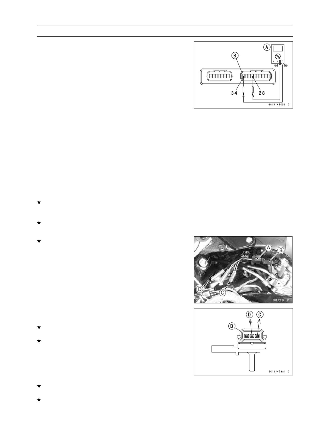
• Measure the output voltage at the ECU in the same way
as input voltage inspection. Note the following.
Digital Meter [A]
Connector [B]
Special Tool - Needle Adapter Set: 57001-1457
Inlet Air Pressure Sensor Output Voltage
Connections to ECU
Meter (+) → Y/BL lead (terminal 28)
Meter (-) → BR/BK lead (terminal 34)
Output Voltage at ECU
Usable Range: DC 3.80 ∼ 4.20 V at the standard
atmospheric pressure (101.32 kPa, 76
cmHg abs.)
NOTE
○The output voltage changes according to the local at-
mospheric pressure.
○The vacuum sensor output voltage is based on a nearly
perfect vacuum in the small chamber of the sensor. So,
the sensor indicates absolute vacuum pressure.
If the output voltage is within the usable range, check the
ECU for its ground, and power supply (see ECU Power
Supply Inspection).
If the ground and power supply are good, replace the ECU
(see ECU section).
If the output voltage is far out of the usable range, check
the output voltage again at the sensor connector [A]
(when the lead is open, the output voltage is about 1.8
V).
• Connect a digital meter to the harness adapter leads.
Inlet Air Pressure Sensor [B]
Special Tool - Sensor Harness Adapter: 57001-1561
Inlet Air Pressure Sensor Output Voltage
Connections to Adapter
Meter (+) → G/W (sensor Y/BL) lead [C]
Meter (-) → BK (sensor BR/BK) lead [D]
Measure the input voltage with the engine stopped, and
with the connector joined.
Turn the ignition switch ON.
Output Voltage at Sensor Connector
Usable Range: DC 3.80 ∼ 4.20 V at the standard
atmospheric pressure (101.32 kPa or
76 cmHg abs.)
• Turn the ignition switch OFF.
If the output voltage is normal, check the wiring for conti-
nuity (see wiring diagram in this section).
If the output voltage is out of the usable range, replace
the sensor.
3-54 FUEL SYSTEM (DFI)
Inlet Air Pressure Sensor (Service Code 12)
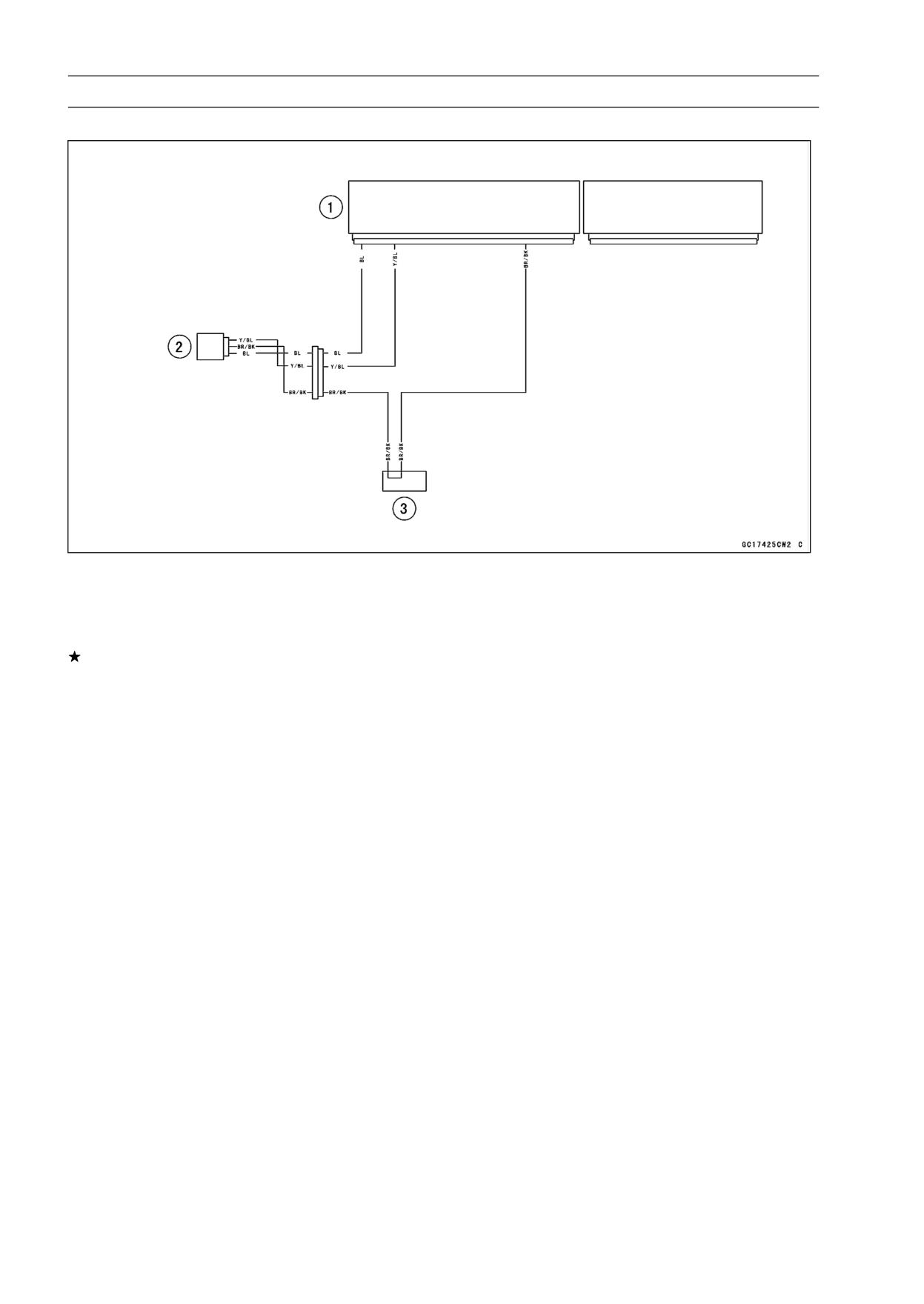
Inlet Air Pressure Sensor Circuit
1. ECU
2. Inlet Air Pressure Sensor
3. Water-proof Joint 2
If you need to check the inlet air pressure sensor for vac-
uum other than 76 cmHg (abs.), check the output voltage
as follows.
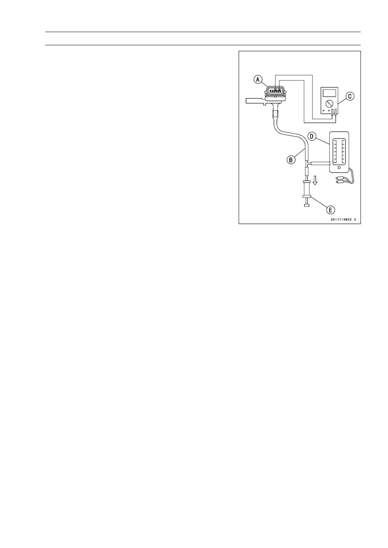
FUEL SYSTEM (DFI) 3-55
Inlet Air Pressure Sensor (Service Code 12)
• Remove the inlet air pressure sensor [A] and disconnect
the vacuum hose from the sensor.
• Connect an auxiliary hose [B] to the inlet air pressure sen-
sor.
• Temporarily install the inlet air pressure sensor.
○Connect a digital meter [C], vacuum gauge [D], and the
fork oil level gauge [E] to the inlet air pressure sensor.
Special Tools - Fork Oil Level Gauge: 57001-1290
Vacuum Gauge: 57001-1369
Sensor Harness Adapter: 57001-1561
Inlet Air Pressure Sensor Output Voltage Connection to
Adapter
Meter (+) → G/W (sensor Y/BL) lead
Meter (-) → BK (sensor BR/BK) lead
○Turn the ignition switch ON.
○Measure the inlet air pressure sensor output voltage from
various vacuum readings, while pulling the handle of the
fork oil level gauge.
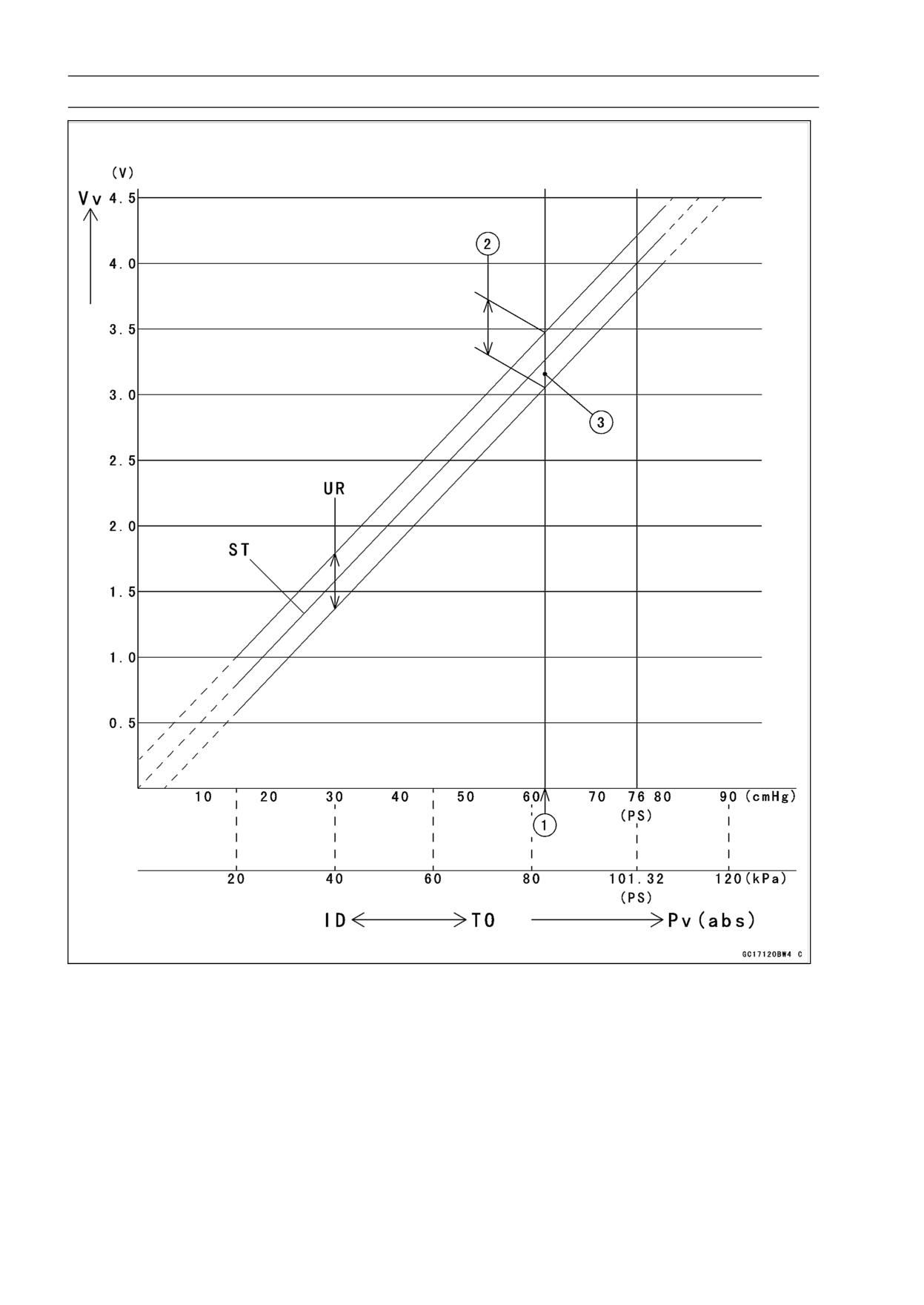
○Check the inlet air pressure sensor output voltage, using
the following formula and chart.
Suppose:
Pg : Vacuum Pressure (gauge) of Throttle Assy
Pl : Local Atmospheric Pressure (abs.) measured by a
barometer
Pv : Vacuum Pressure (abs.) of Throttle Assy
Vv : Sensor Output Voltage (v)
then
Pv = Pl - Pg
For example, suppose the following data is obtained:
Pg = 8 cmHg (vacuum gauge reading)
Pl = 70 cmHg (barometer reading)
Vv = 3.2 V (digital volt meter reading)
then
Pv = 70 - 8 = 62 cmHg (abs.)
Plot this Pv (62 cmHg) at a point [1] on the chart and draw a
vertical line through the point. Then, you can get the usable
range [2] of the sensor output voltage.
Usable range = 3.08 ∼ 3.48 V
Plot Vv (3.2 V) on the vertical line. → Point [3].
Results: In the chart, Vv is within the usable range and
the sensor is normal.
3-56 FUEL SYSTEM (DFI)
Inlet Air Pressure Sensor (Service Code 12)
ID: Idling
Pv: Throttle Vacuum Pressure (abs.)
Ps: Standard Atmospheric Pressure (abs.)
ST: Standard of Sensor Output Voltage (v)
TO: Throttle Full Open
UR: Usable Range of Sensor Output Voltage (v)
Vv: Inlet Air Pressure Sensor Output Voltage (V) (Digital Meter Reading)
FUEL SYSTEM (DFI) 3-57
Inlet Air Temperature Sensor (Service Code 13)
Removal/Installation
CAUTION
Never drop the sensor, especially on a hard surface.
Such a shock to the sensor can damage it.
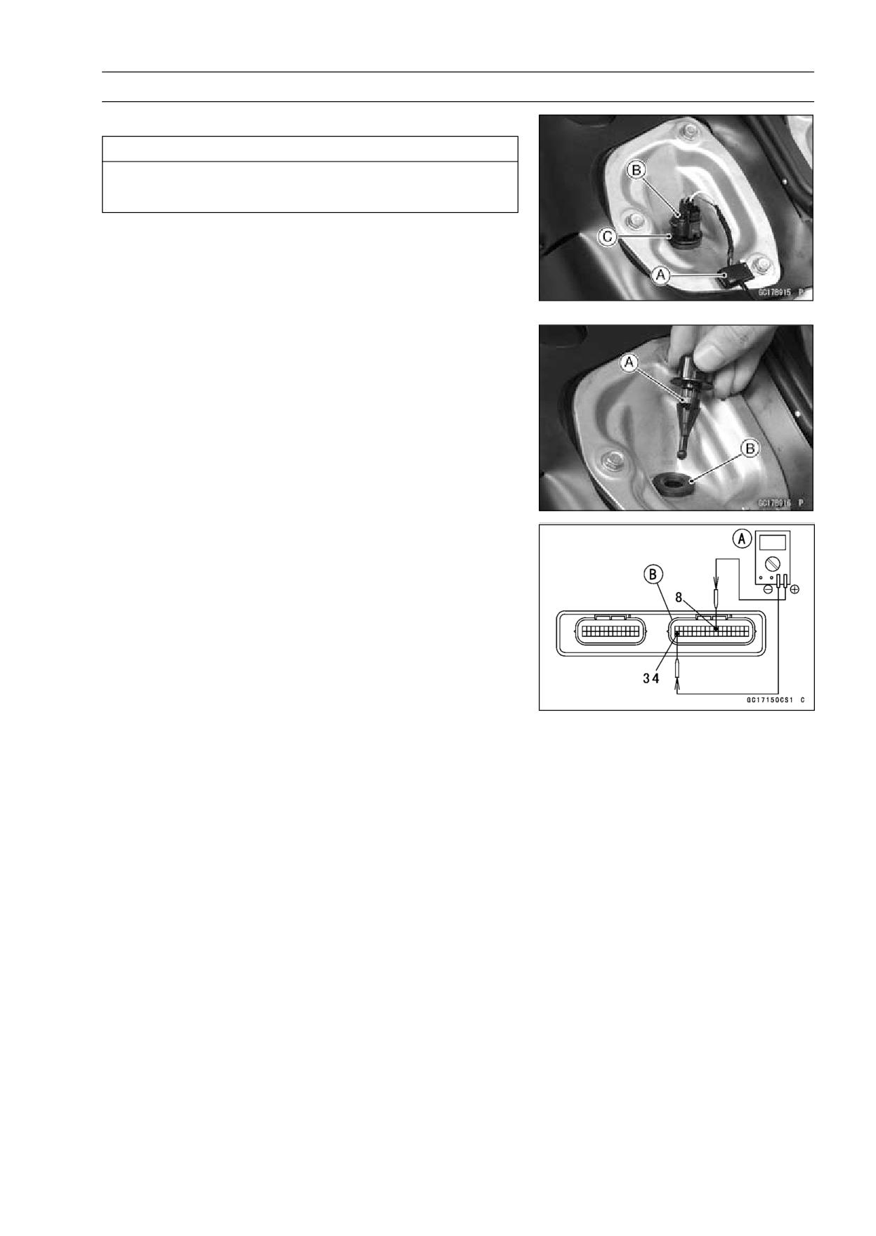
• Remove the fuel tank (see Fuel Tank Removal).
• Open the clamp [A]
• Disconnect the connector [B] from the inlet air tempera-
ture sensor.
• Pull out the inlet air temperature sensor [C].
• Install the inlet air temperature sensor [A] in the grommet
[B].
Output Voltage Inspection
NOTE
○Be sure the battery is fully charged.
• Remove the ECU (see ECU Removal).
○Do not disconnect the ECU connectors.
• Connect a digital meter to the ECU connector, using nee-
dle adapter set.
Special Tool - Needle Adapter Set: 57001-1457
Inlet Air Temperature Sensor Output Voltage
Connections to ECU Connector
Meter (+) → Y lead (terminal 8)
Meter (-) → BR/BK lead (terminal 34)
• Measure the sensor output voltage with the engine
stopped and the connector joined.
• Turn the ignition switch ON.
Output Voltage at ECU
Standard: About 2.25 ∼ 2.50 V at inlet air temperature
20°C (68°F)
NOTE
○The output voltage changes according to the inlet air
temperature.
• Turn the ignition switch OFF.
3-58 FUEL SYSTEM (DFI)
Inlet Air Temperature Sensor (Service Code 13)
If the output voltage is out of the specified, check the ECU
for its ground, and power supply (see ECU Power Supply
Inspection).
If the ground and power supply are good, replace the ECU
(see ECU section).
If the output voltage is far out of the specified (e.g. when
the wiring is open, the voltage is about 4.6 V), check the
wiring (see wiring diagram in this section).
If the wiring is good, check the sensor resistance.
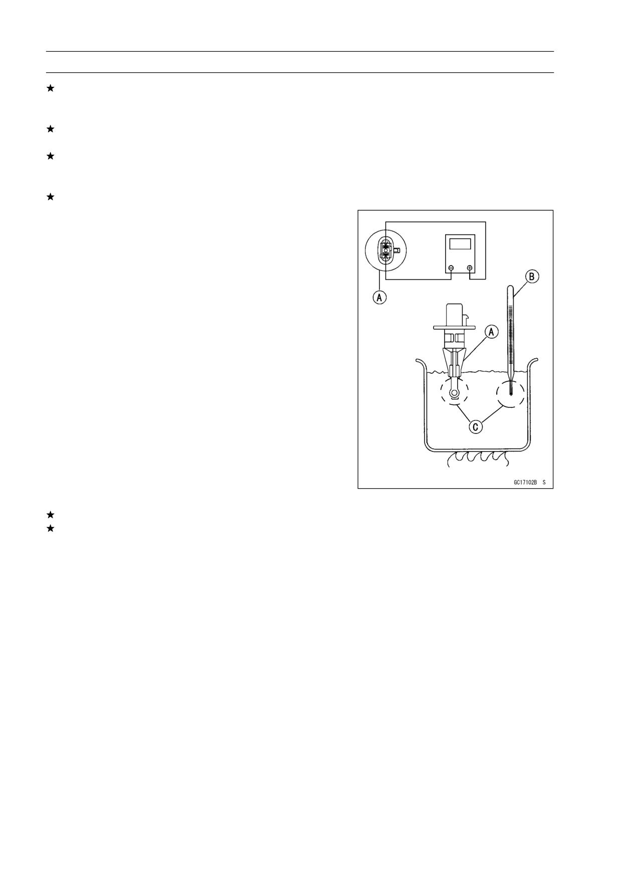
Sensor Resistance Inspection
• Remove the inlet air temperature sensor (see Re-
moval/Installation).
• Suspend the sensor [A] in a container of machine oil so
that the heat-sensitive portion is submerged.
• Suspend a thermometer [B] with the heat-sensitive por-
tion [C] located in almost the same depth with the sensor.
NOTE
○The sensor and thermometer must not touch the con-
tainer side or bottom.
• Place the container over a source of heat and gradually
raise the temperature of the oil while stirring the oil gently
for even temperature.
• Using a digital meter, measure the internal resistance
of the sensor across the terminals at the temperatures
shown in the table.
Inlet Air Temperature Sensor Resistance
Standard:
2.09 ∼ 2.81 kΩ at 20°C (68°F)
About 0.322 kΩ at 80°C (176°F) (reference
value)
If the measurement is out of the range, replace the sensor.
If the measurement is within the specified, replace the
ECU (see ECU section).
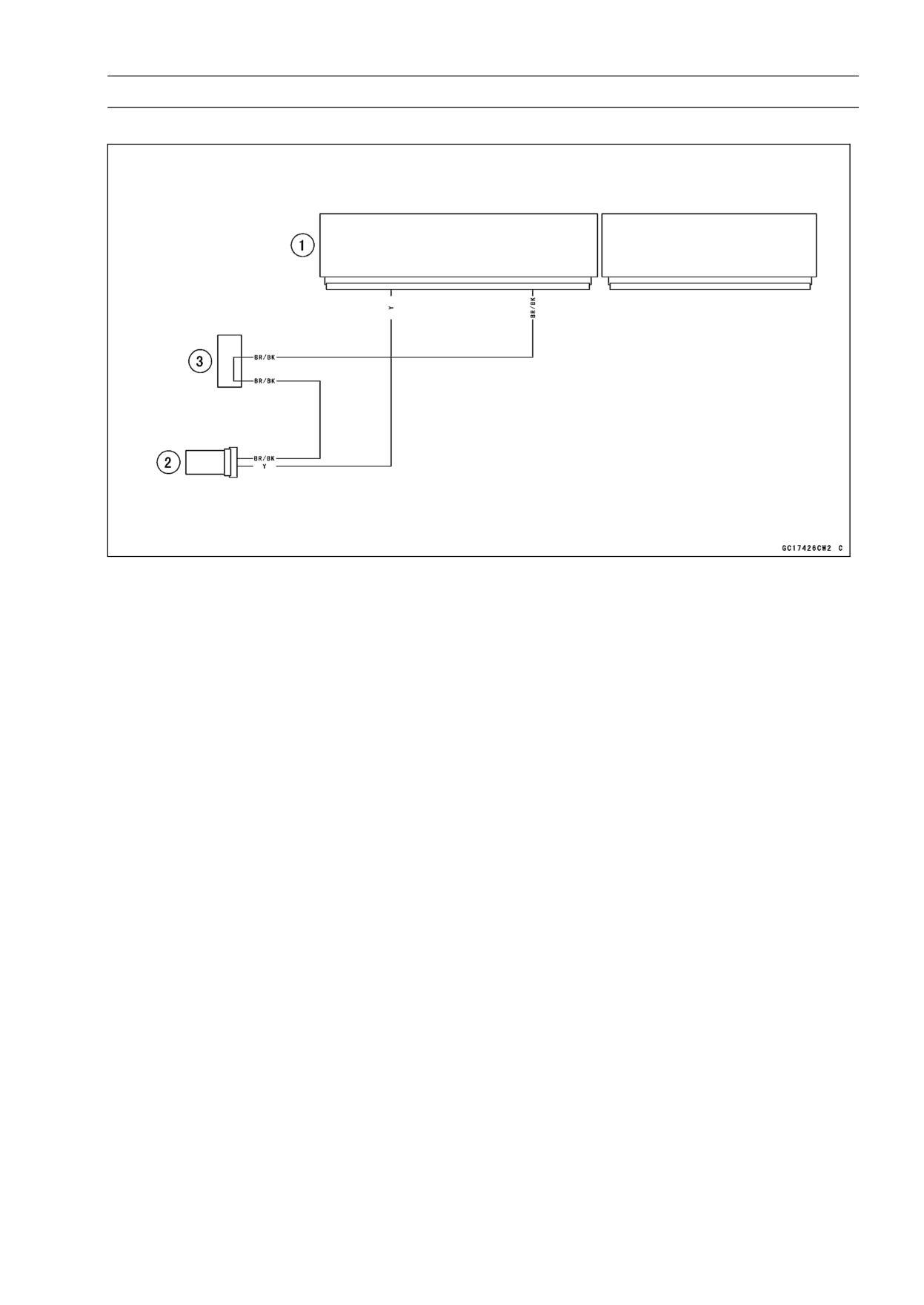
FUEL SYSTEM (DFI) 3-59
Inlet Air Temperature Sensor (Service Code 13)
Inlet Air Temperature Sensor Circuit
1. ECU
2. Inlet Air Temperature Sensor
3. Water-proof Joint 2
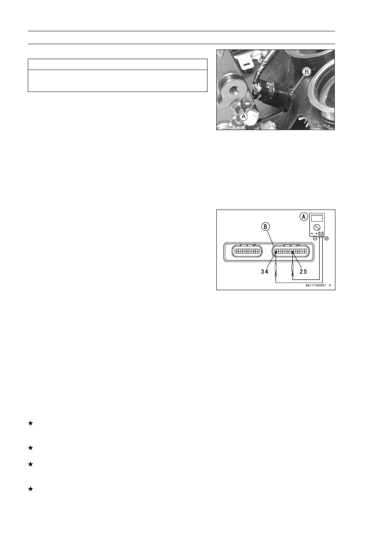
3-60 FUEL SYSTEM (DFI)
Water Temperature Sensor (Service Code 14)
Removal/Installation
CAUTION
Never drop the sensor, especially on a hard surface.
Such a shock to the sensor can damage it.
• Drain the coolant (see Coolant Change in the Periodic
Maintenance chapter).
• Remove:
Throttle Body Assy (see Throttle Body Assy Removal)
Connector [A]
Water Temperature Sensor [B]
• Replace the gasket with a new one, and tighten the water
temperature sensor.
Torque - Water Temperature Sensor: 25 N·m (2.5 kgf·m, 18
ft·lb)
• Fill the engine with coolant and bleed the air from the cool-
ing system (see Coolant Change in the Periodic Mainte-
nance chapter).
Output Voltage Inspection
NOTE
○Be sure the battery is fully charged.
• Remove the ECU (see ECU Removal).
○Do not disconnect the ECU connectors.
• Connect a digital meter [A] to the ECU connectors [B],
with the needle adapter set.
Special Tool - Needle Adapter Set: 57001-1457
Water Temperature Sensor Output Voltage
Connections to ECU
Meter (+) → O lead (terminal 25)
Meter (-) → BR/BK lead (terminal 34)
• Measure the sensor output voltage with the engine
stopped and the connector joined.
• Turn the ignition switch ON.
Output Voltage at ECU
Standard: About 2.80 ∼ 2.97 V at 20°C (68°F)
NOTE
○The output voltage changes according to the coolant
temperature in the engine.
• Turn the ignition switch OFF.
If the output voltage is out of the specified, check the ECU
for its ground, and power supply (see ECU Power Supply
Inspection).
If the ground and power supply are good, replace the ECU
(see ECU section).
If the output voltage is far out of the specified (e.g. when
the wiring is open, the voltage is about 5V), check the
wiring (see wiring diagram in this section).
If the wiring is good, check the water temperature sensor
resistance.
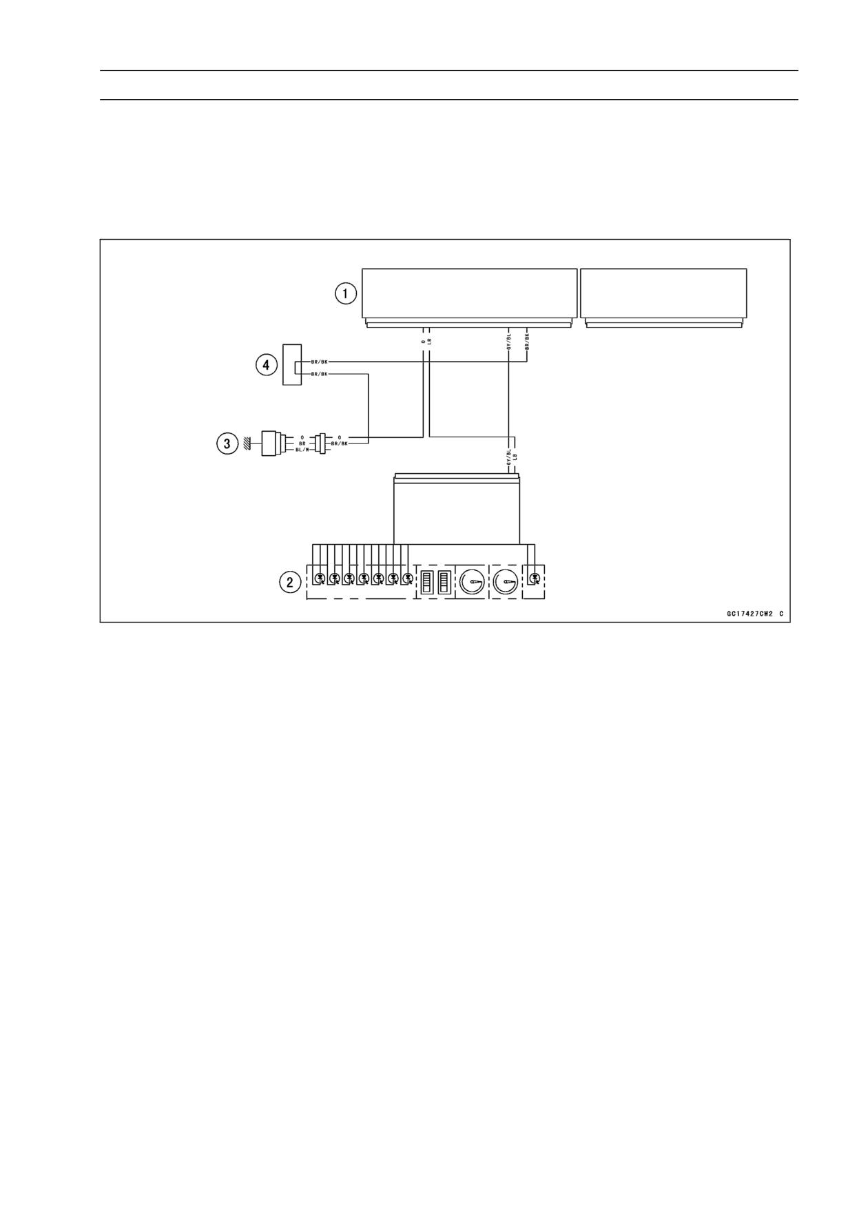
FUEL SYSTEM (DFI) 3-61
Water Temperature Sensor (Service Code 14)
Sensor Resistance Inspection
• Refer to the Water Temperature Sensor Inspection in the
Electrical System chapter (see Water Temperature Sen-
sor Inspection in the Electrical System chapter).
Water Temperature Sensor Circuit
1. ECU
2. Meter Unit
3. Water Temperature Sensor
4. Water-proof Joint 2
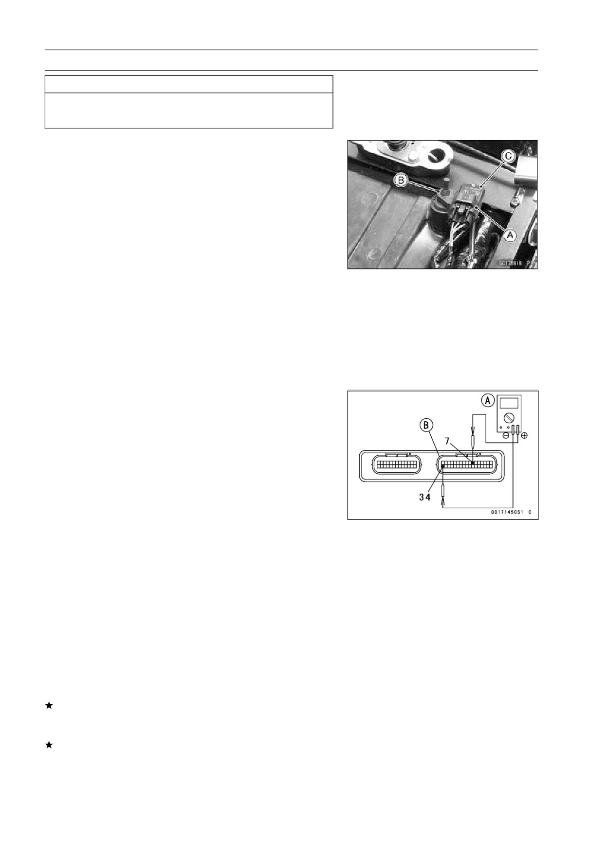
3-62 FUEL SYSTEM (DFI)
Atmospheric Pressure Sensor (Service Code 15)
CAUTION
Never drop the sensor, especially on a hard surface.
Such a shock to the sensor can damage it.
Removal
• Remove:
Seat (see Seat Removal in the Frame chapter)
Atmospheric Pressure Sensor Connector [A]
Damper [B]
Atmospheric Pressure Sensor [C]
Installation
NOTE
○The atmospheric pressure sensor is the same part as
the inlet air pressure sensor except that the inlet air
pressure sensor has a inlet air pressure hose and dif-
ferent wiring.
• Installation is reverse of removal.
Input Voltage Inspection
NOTE
○Be sure the battery is fully charged.
○The inspection is the same as “Input Voltage Inspection”
of the throttle sensor and the inlet air pressure sensor.
• Turn the ignition switch OFF.
• Remove the ECU (see ECU Removal).
○Do not disconnect the ECU connectors.
• Connect a digital meter [A] to the connector [B], with the
needle adapter set.
Special Tool - Needle Adapter Set: 57001-1457
Atmospheric Pressure Sensor Input Voltage
Connections to ECU Connector
Meter (+) → BL lead (terminal 7)
Meter (-) → BR/BK lead (terminal 34)
• Measure the input voltage with the engine stopped, and
with the connectors joined.
• Turn the ignition switch ON.
Input Voltage at ECU
Standard: DC 4.75 ∼ 5.25 V
If the reading of input voltage is less than the standard
range, check the ECU for its ground, and power supply
(see ECU Power Supply Inspection).
If the ground and power supply are good, replace the ECU
(see ECU section).
FUEL SYSTEM (DFI) 3-63
Atmospheric Pressure Sensor (Service Code 15)
If the reading is within the standard range, remove the
seat, and check the input voltage again at the sensor con-
nector.
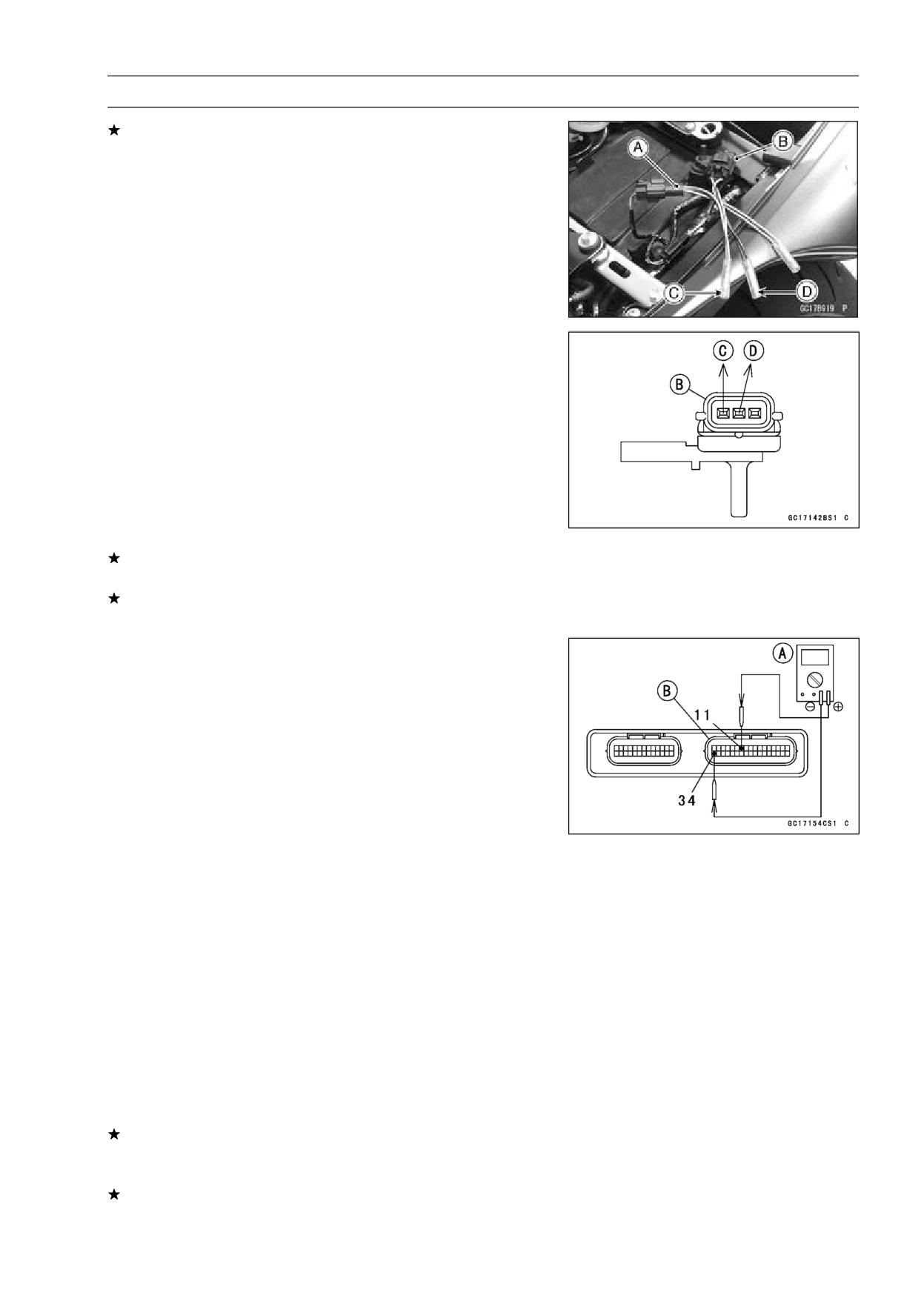
• Disconnect the atmospheric pressure sensor connector
and connect the harness adapter [A] between the harness
connector and atmospheric pressure sensor connector.
Special Tool - Sensor Harness Adapter: 57001-1561
• Connect a digital meter to the harness adapter leads.
Atmospheric Pressure Sensor [B]
Atmospheric Pressure Sensor Input Voltage
Connections to Adapter
Meter (+) → G (sensor BL) lead [C]
Meter (-) → BK (sensor BR/BK) lead [D]
• Measure the input voltage with the engine stopped, and
with the connector joined.
• Turn the ignition switch ON.
Input Voltage at Sensor Connector
Standard: DC 4.75 ∼ 5.25 V
• Turn the ignition switch OFF.
If the reading is out of the standard range, check the
wiring (see wiring diagram in this section).
If the reading is good, the input voltage is normal. Check
the output voltage.
Output Voltage Inspection
• Measure the output voltage at the ECU in the same way
as input voltage inspection. Note the following.
Digital Meter [A]
ECU Connector [B]
Special Tool - Needle Adapter Set: 57001-1457
Atmospheric Pressure Sensor Output Voltage
Connections to ECU Connector
Meter (+) → G/W lead (terminal 11)
Meter (-) → BR/BK lead (terminal 34)
Output Voltage
Usable Range: DC 3.80 ∼ 4.20 V at the standard
atmospheric pressure (101.32 kPa, 76
cmHg abs.)
NOTE
○The output voltage changes according to the local at-
mospheric pressure.
○The atmospheric sensor output voltage is based on
a nearly perfect vacuum in the small chamber of the
sensor. So, the sensor indicates absolute atmospheric
pressure.
If the output voltage is within the usable range, check the
ECU for its ground, and power supply (see ECU Power
Supply Inspection).
If the ground and power supply are good, replace the ECU
(see ECU section).
3-64 FUEL SYSTEM (DFI)
Atmospheric Pressure Sensor (Service Code 15)
If the output voltage is far out of the usable range, check
the output voltage at the sensor connector [A] (when the
wiring is open, the output voltage is about 1.8 V).
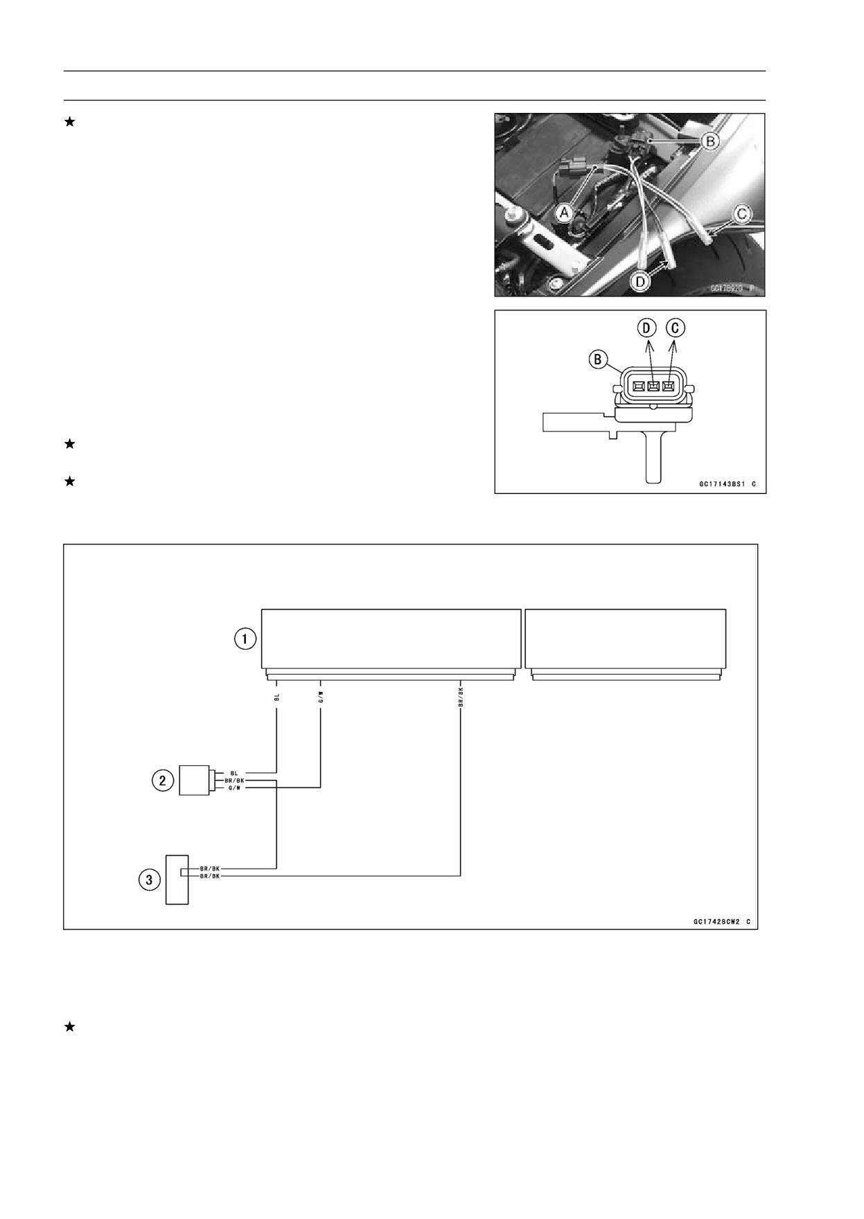
• Connect a digital meter [A] to the harness adapter leads.
Atmospheric Pressure Sensor [B]
Special Tool - Sensor Harness Adapter: 57001-1561
Atmospheric Pressure Sensor Output Voltage
Connections to Adapter
Meter (+) → G/W (sensor G/W) lead [C]
Meter (-) → BK (sensor BR/BK) lead [D]
Output Voltage at Sensor
Usable Range: DC 3.80 ∼ 4.20 V at the standard
atmospheric pressure (101.32 kPa, 76
cmHg abs.)
• Turn the ignition switch OFF.
If the output voltage is normal, check the wiring for conti-
nuity (see wiring diagram in this section).
If the output voltage is out of the usable range, replace
the sensor.
Atmospheric Pressure Sensor Circuit
1. ECU
2. Atmospheric Pressure Sensor
3. Water-proof Joint 2
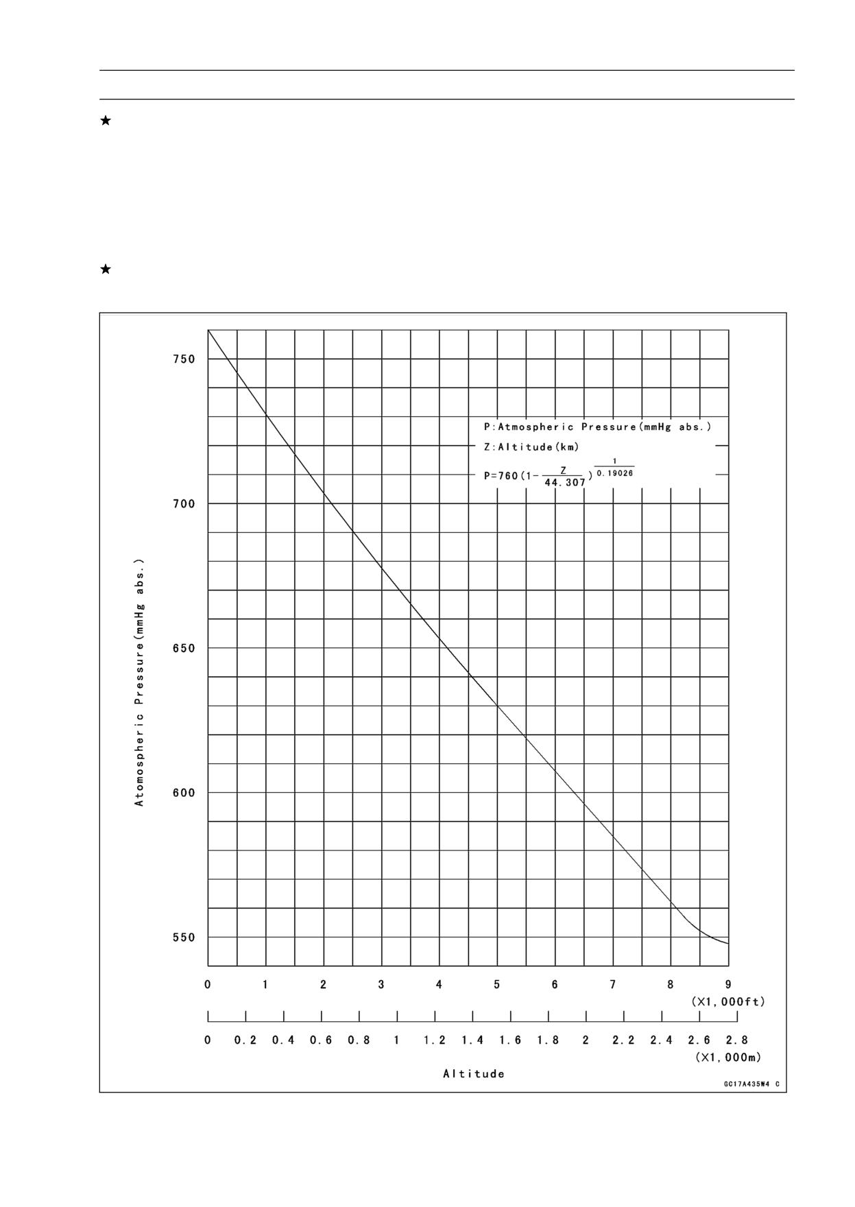
If you need to check the atmospheric pressure sensor for
various altitudes other than sea level, check the output
voltage as follows.
○Determine the local altitude (Elevation).
FUEL SYSTEM (DFI) 3-65
Atmospheric Pressure Sensor (Service Code 15)
If you know the local atmospheric pressure using a
barometer, substitute the atmospheric pressure for throt-
tle vacuum pressure in the inlet air pressure sensor chart
(see Inlet Air Pressure Sensor section). And get the
usable range of the atmospheric pressure sensor output
voltage and check if output voltage is within the standard
or not in the same way as Output Voltage Inspection of
the inlet air pressure sensor.
If you know the local altitude, use the following chart.
Atmospheric Pressure/Altitude Relationship
3-66 FUEL SYSTEM (DFI)
Crankshaft Sensor (Service Code 21)
Crankshaft Sensor Removal/Installation
• Refer to the Crankshaft Sensor Removal/Installation in
the Electrical System chapter (see Crankshaft Sensor Re-
moval/Installation in the Electrical System chapter).
Crankshaft Sensor Inspection
○The crankshaft have no power source, and when the en-
gine stops, the crankshaft generates no signals.
• Crank the engine and measure the peak voltage of the
crankshaft sensor (see Crankshaft Sensor Peak Voltage
Inspection in the Electrical System chapter) in order to
check the sensor.
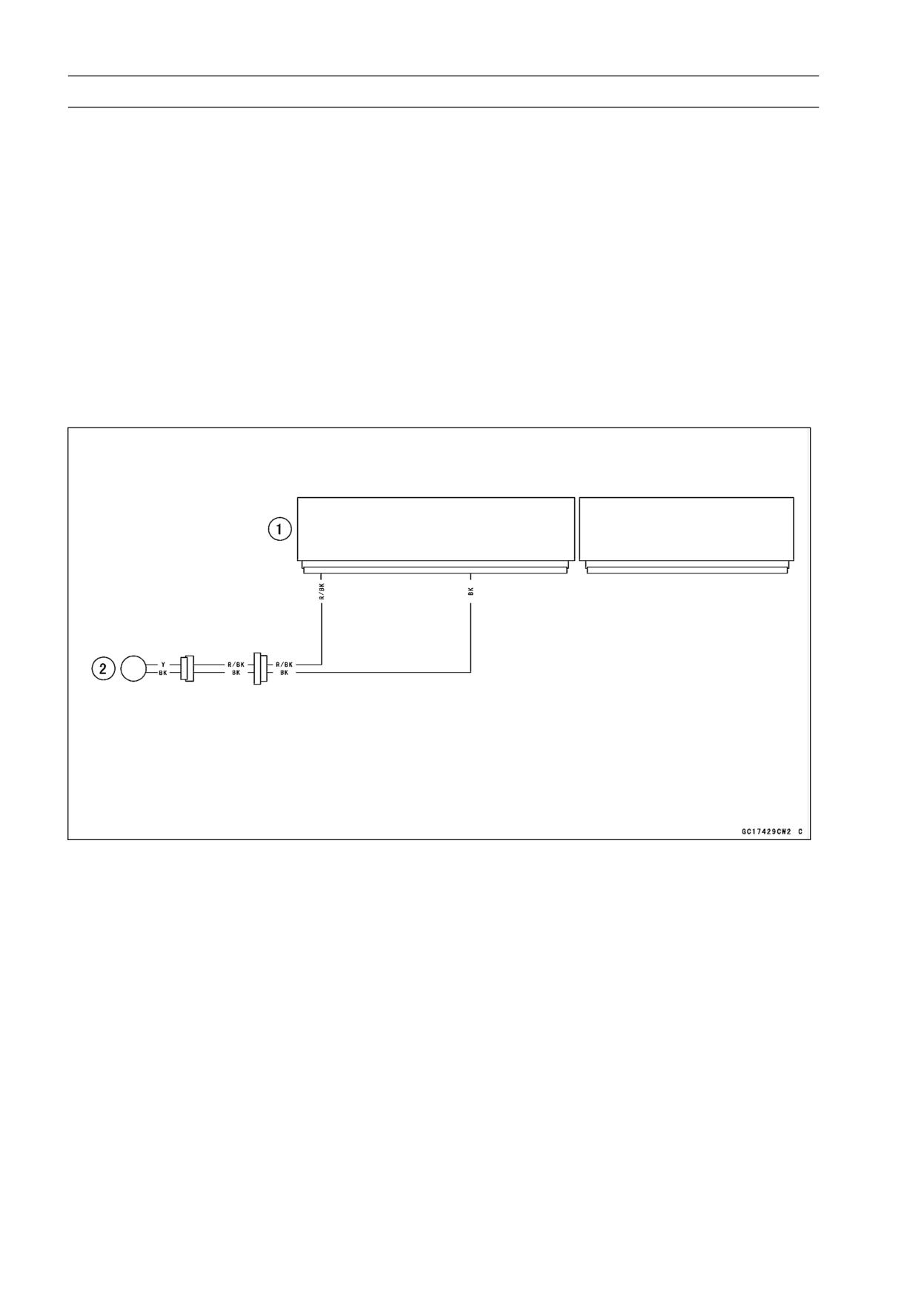
• Check the wiring for continuity (see wiring diagram in this
section).
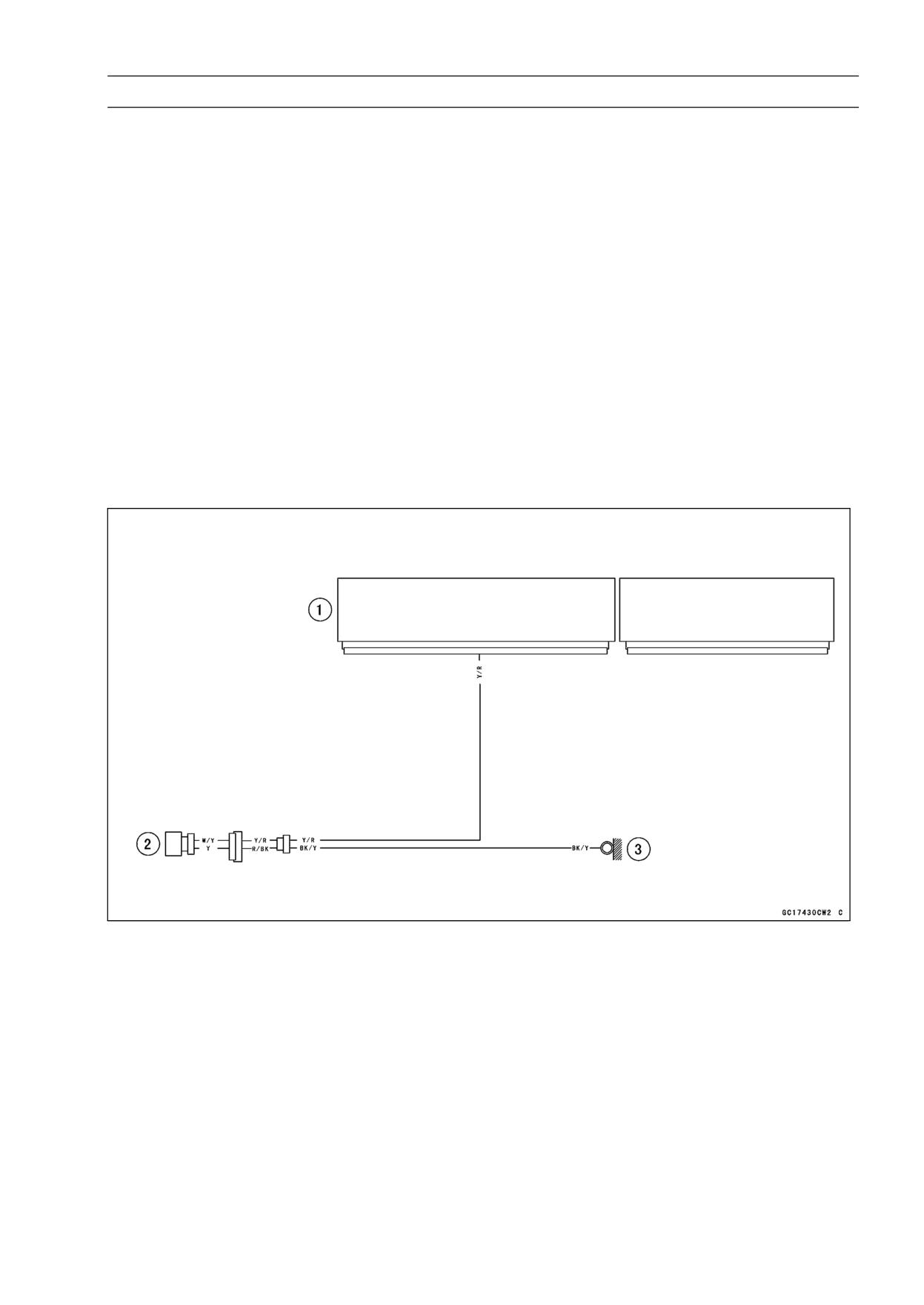
Crankshaft Sensor Circuit
1. ECU
2. Crankshaft Sensor
FUEL SYSTEM (DFI) 3-67
Camshaft Position Sensor (Service Code 23)
Camshaft Position Sensor Removal/Installation
The camshaft position sensor detects the position of the
camshaft, and distinguishes the cylinder.
• Refer to the Camshaft Position Sensor Removal/Installa-
tion in the Electrical System chapter (see Camshaft Posi-
tion Sensor Removal/Installation in the Electrical System
chapter).
Camshaft Position Sensor Inspection
○The camshaft position sensor have no power source, and
when the engine stops, the camshaft position sensor gen-
erates no signal.
• Crank the engine and measure the peak voltage of the
camshaft position sensor (see Camshaft Position Sensor
Peak Voltage Inspection in the Electrical System chapter)
in order to check the sensor.
• Check the wiring for continuity (see wiring diagram in this
section).
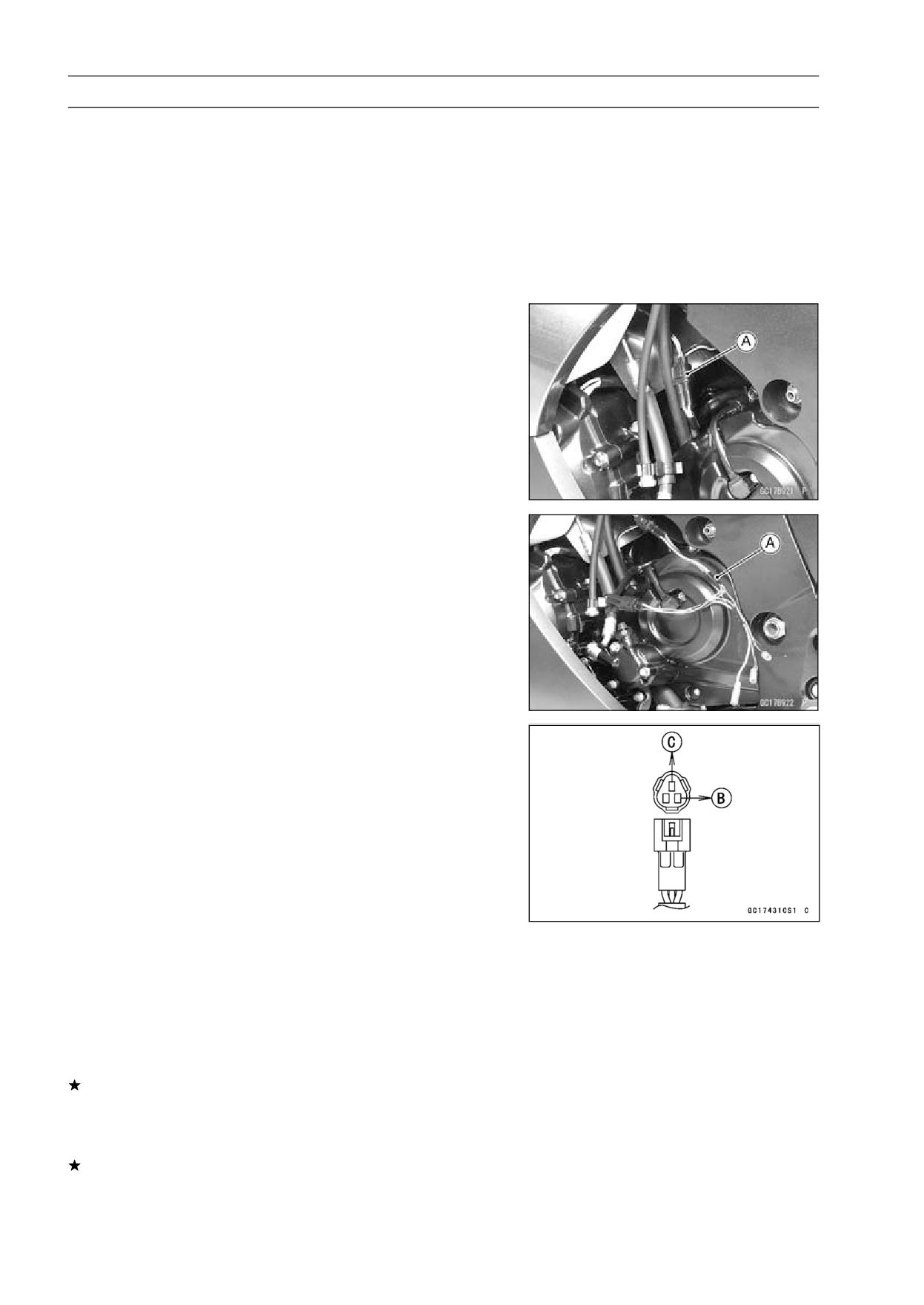
Camshaft Position Sensor Circuit
1. ECU
2. Camshaft Position Sensor
3. Frame Ground 1
3-68 FUEL SYSTEM (DFI)
Speed Sensor (Service Code 24)
Speed Sensor Removal/Installation
• Refer to the Speed Sensor Removal/Installation in
the Electrical System chapter (see Speed Sensor Re-
moval/Installation in the Electrical System chapter).
Speed Sensor Inspection
• Refer to the Speed Sensor Inspection in the Electrical
System chapter (see Speed Sensor Inspection in the
Electrical System chapter).
Input Voltage Inspection
NOTE
○Be sure the battery is fully charged.
• Turn the ignition switch OFF.
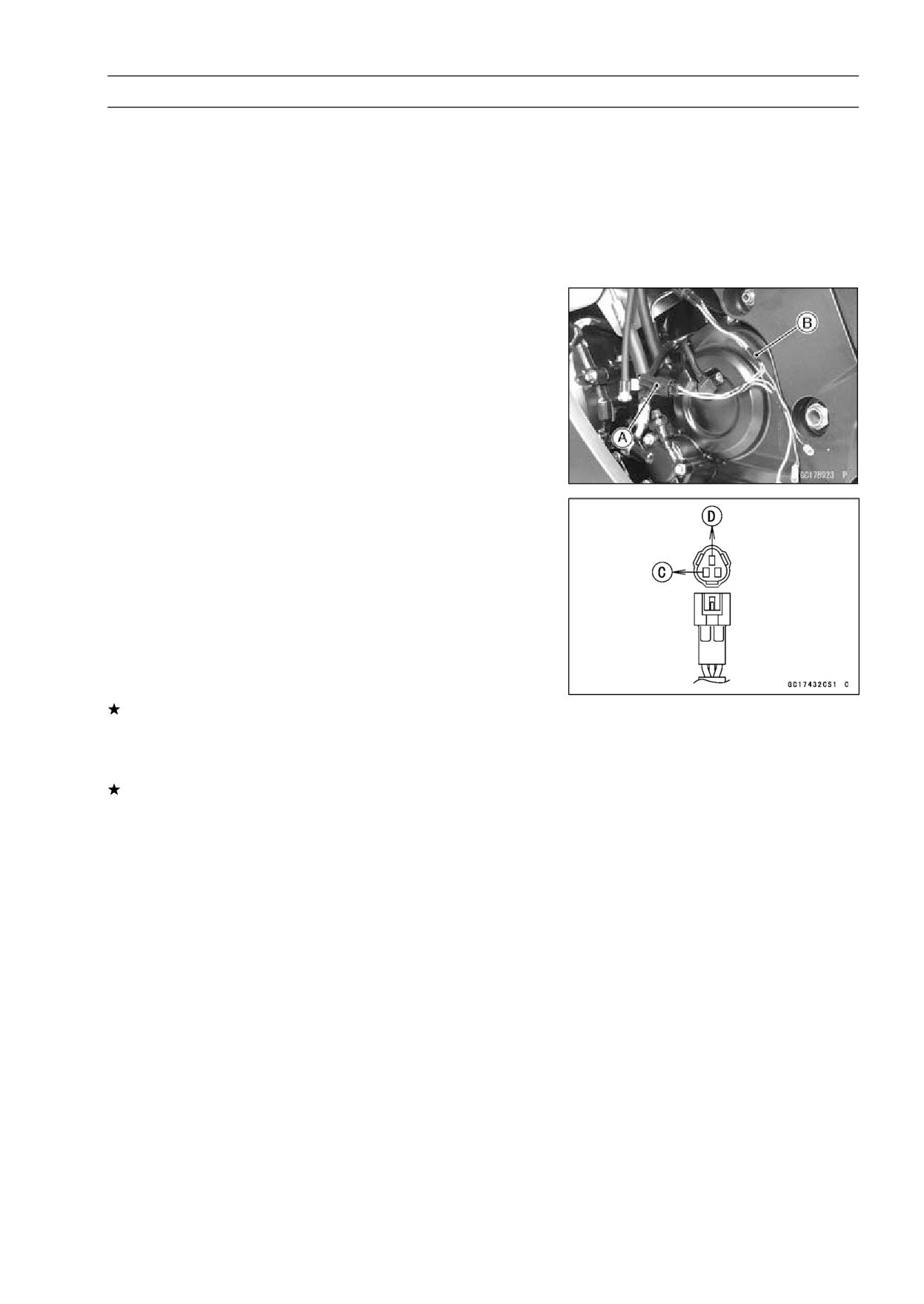
• Disconnect the speed sensor connector [A].
• Connect the harness adapter [A] between the harness
connector and speed sensor connector.
Special Tool - Throttle Sensor Setting Adapter #1: 57001
-1400
• Connect a digital meter to the harness adapter leads.
Speed Sensor Input Voltage
Connections to Adapter
Meter (+) → BL (sensor P) lead [B]
Meter (-) → BK/BL (sensor BK) lead [C]
• Measure the input voltage with the engine stopped, and
with the connector joined.
• Turn the ignition switch ON.
Input Voltage
Standard: About DC 9 ∼ 11 V
• Turn the ignition switch OFF.
If the reading is out of the range, check the wiring (see
wiring diagram in this section), and meter unit (see Elec-
tronic Combination Meter Unit Inspection in the Electrical
System chapter).
If the reading is good, check the output voltage.
FUEL SYSTEM (DFI) 3-69
Speed Sensor (Service Code 24)
Output Voltage Inspection
• Before this inspection, inspect the input voltage (see Input
Voltage Inspection in this section).
NOTE
○Be sure the battery is fully charged.
• Turn the ignition switch OFF.
• Using the stand, raise the rear wheel off the ground.
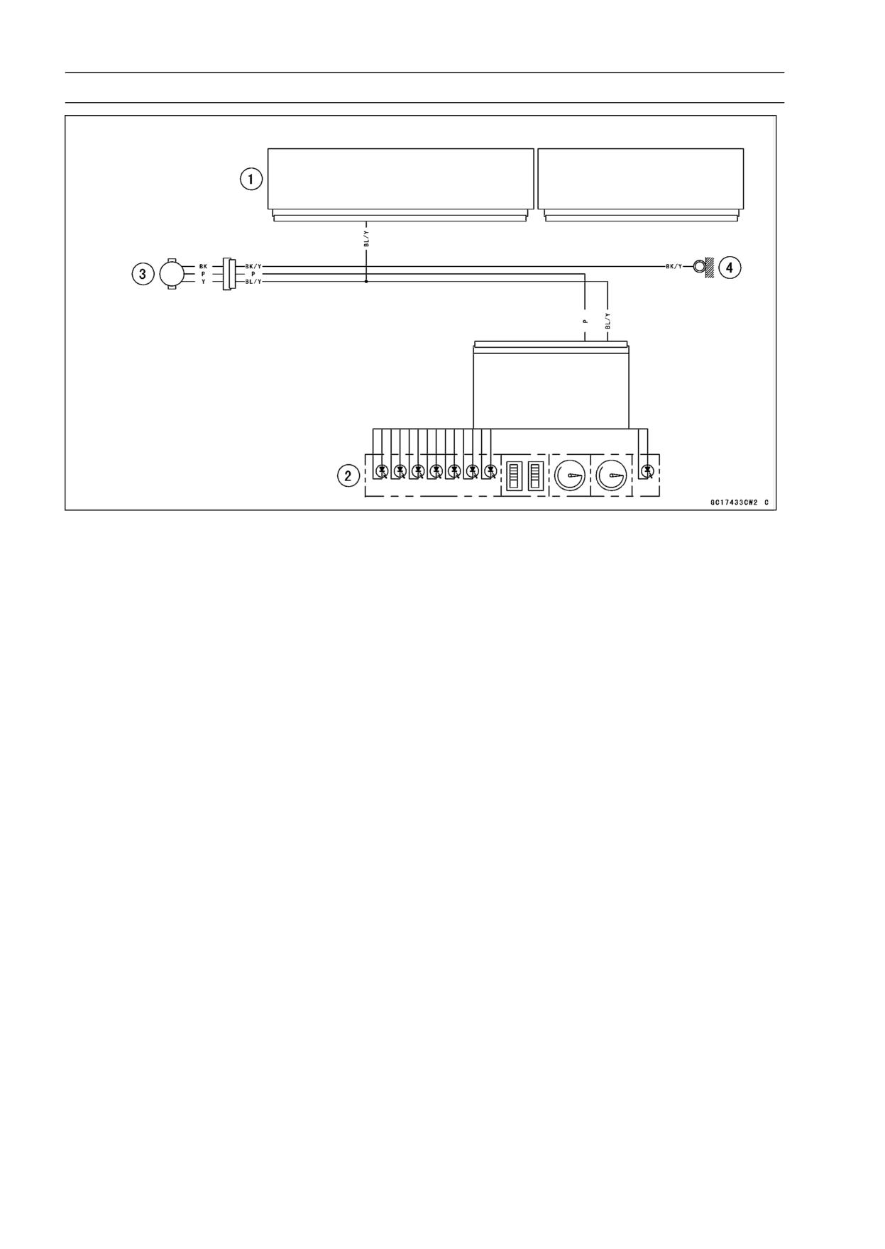
• Disconnect the speed sensor connector [A] and connect
the harness adapter [B] between the harness connector
and speed sensor connector.
• Connect a digital meter to the harness adapter leads.
Special Tool - Throttle Sensor Setting Adapter #1: 57001
-1400
Speed Sensor Output Voltage
Connections to Adapter
Meter (+) → BY (sensor BL/Y) lead [C]
Meter (-) → BK/BL (sensor BK) lead [D]
• Measure the output voltage with the engine stopped, and
with the connector joined.
• Turn the ignition switch ON.
Output Voltage at Sensor
Standard:
About DC 0.05 ∼ 0.09 V or DC 4.5 ∼ 4.9
• Rotate the rear wheel by hand, confirm the output voltage
will be raise or lower.
• Turn teh ignition switch OFF.
If the reading is out of the range, check the speed sensor
(see Speed Sensor Inspection in the Electrical System
chapter) and the wiring to ECU (see wiring diagram in this
section).
If the reading, speed sensor and wiring are good, replace
the ECU (see ECU section).
3-70 FUEL SYSTEM (DFI)
Speed Sensor (Service Code 24)
1. ECU
2. Meter Unit
3. Speed Sensor
4. Frame Ground 1
FUEL SYSTEM (DFI) 3-71
Gear Position Switch (Service Code 25)
Gear Position Switch Removal/Installation
• Refer to the Gear Position Switch Removal/Installation in
the Electrical System chapter (see Gear Position Switch
Removal/Installation in the Electrical System chapter).
Gear Position Switch Inspection
• Refer to the Gear Position Switch Inspection in the Electri-
cal System chapter (see Gear Position Switch Inspection
in the Electrical System chapter).
Input Voltage Inspection
NOTE
○Be sure the battery is fully charged.
• Turn the ignition switch OFF.
• Remove the ECU (see ECU Removal).
○Do not disconnect the ECU connectors.
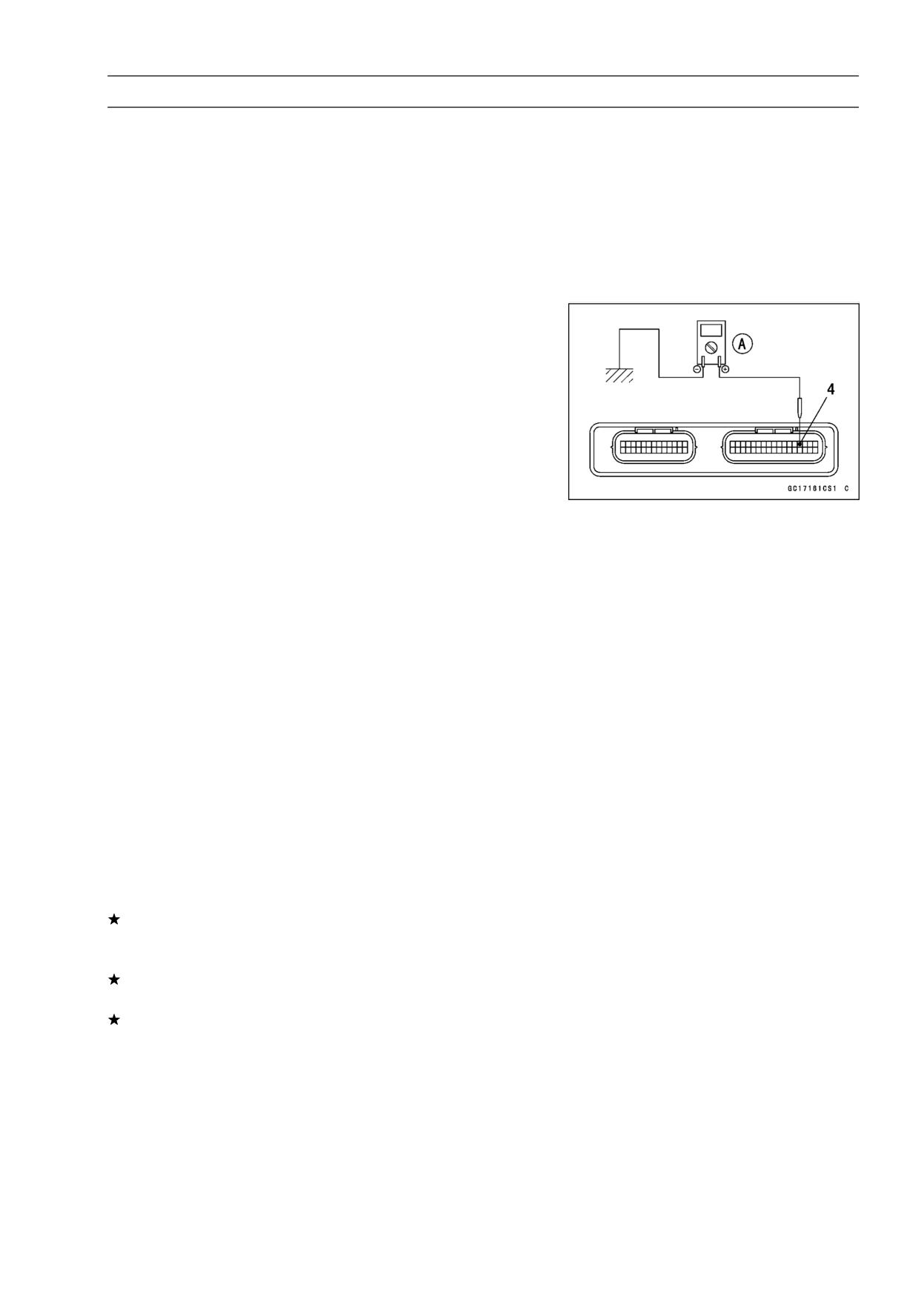
• Connect a digital meter [A] to the connector, with the nee-
dle adapter set.
Special Tool - Needle Adapter Set: 57001-1457
Gear Position Switch Input Voltage at 1 ∼ 6 Gear Positions
Connections to ECU Connector
Meter (+) → G/R lead (terminal 4)
Meter (-) → Engine Ground
• Measure the switch input voltage with the engine stopped,
and with the connector joined.
• Turn the ignition switch ON.
Input Voltage at 1 ∼ 6 Gear Positions
Standard:
1st
About 3.0 V
2nd
About 2.5 V
3rd
About 2.0 V
4th
About 1.5 V
5th
About 1.1 V
6th
About 0.7 V
• Turn the ignition switch OFF.
If the reading is out of the range, check the gear position
switch (see Gear Position Switch Inspection in the Elec-
trical System chapter).
If the switch is good, check the ECU for its ground and
power supply (see ECU Power Supply Inspection).
If the ground and power supply are good, replace the ECU
(see ECU section).
3-72 FUEL SYSTEM (DFI)
Gear Position Switch (Service Code 25)
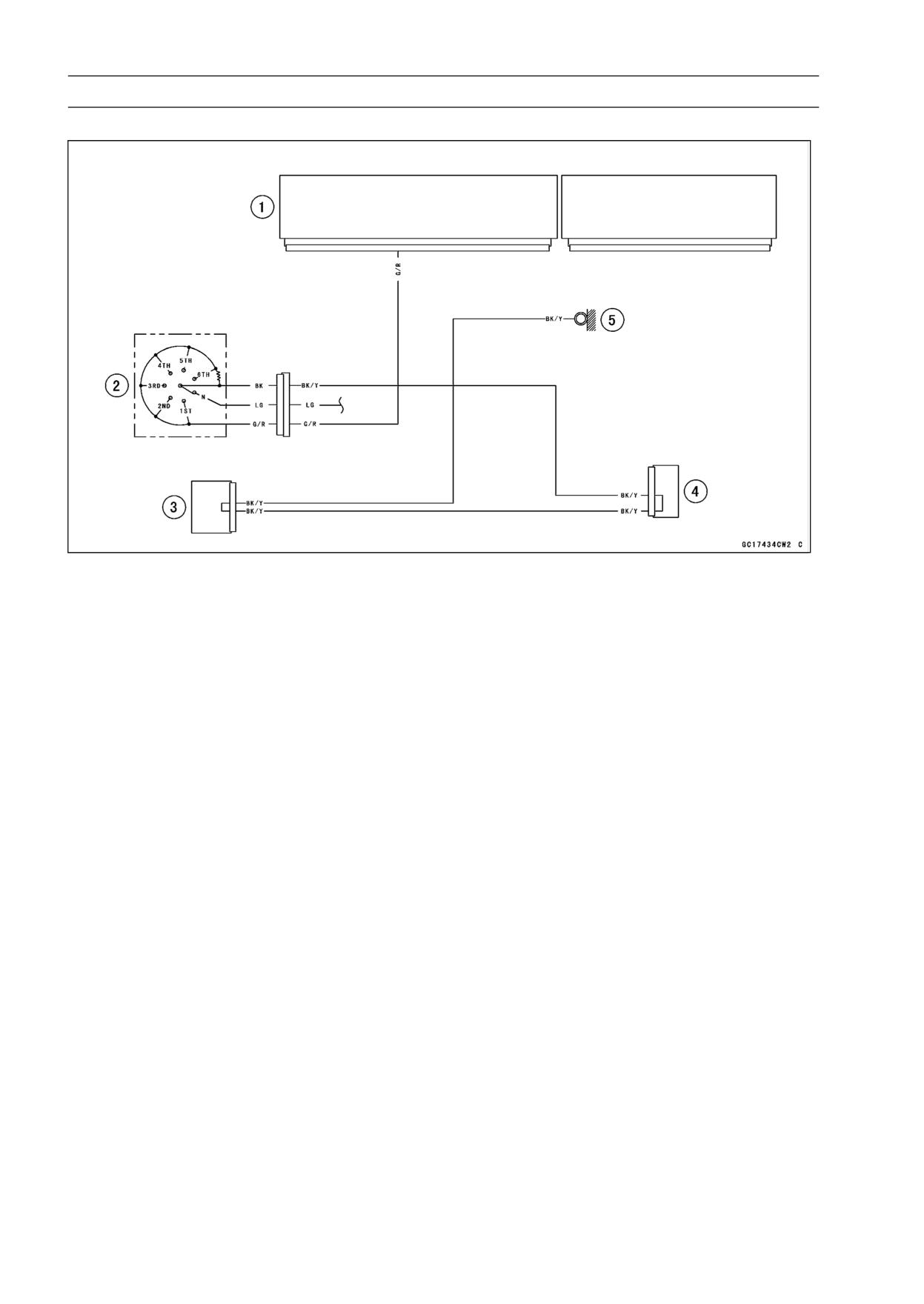
Gear Position Switch Circuit
1. ECU
2. Gear Position Switch
3. Joint Connector 1
4. Joint Connector 2
5. Frame Ground 1
FUEL SYSTEM (DFI) 3-73
Vehicle-down Sensor (Service Code 31)
This sensor has a weight [A] with two magnets inside, and
sends a signal to the ECU. But when the motorcycle banks
60 ∼ 70° or more to either side (in fact falls down), the weight
turns and shuts off the signal. The ECU senses this change,
and stops the fuel pump, the fuel injectors, and the ignition
system.
Hall IC [B]
When the motorcycle is down, the ignition switch is left
ON. If the starter button is pushed, the electric starter turns
but the engine doesn’t start. To start the engine again, raise
the motorcycle, turn the ignition switch OFF, and then ON.
When the ignition switch is turned ON, current flows through
the latch-up circuit and the transistor in the circuit is turned
ON to unlock the latch-up circuit.
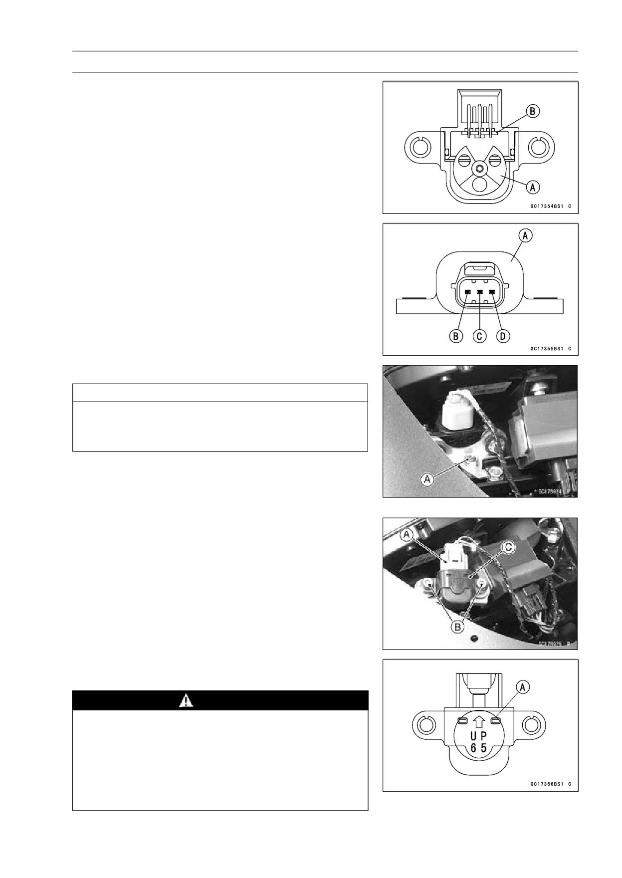
Vehicle-down Sensor [A]
Ground Terminal BR/BK [B]
Output Terminal Y/G [C]
Power Source Terminal BL [D]
Removal
CAUTION
Never drop the vehicle-down sensor, especially on
a hard surface. Such a shock to the sensor can
damage it.
• Remove:
Windshield (see Windshield Removal in the Frame
chapter)
Bolts [A]
• Remove:
Connector [A]
Bolts [B]
Vehicle-down Sensor [C]
Installation
• The UP mark [A] of the sensor should face upward.
WARNING
Incorrect installation of the vehicle-down sensor
could cause sudden loss of engine power. The
rider could lose balance during certain riding situ-
ations, like leaning over in a turn, with the potential
for an accident resulting in injury or death. Ensure
that the vehicle-down sensor is held in place by the
sensor brackets.
• Tighten:
Torque - Vehicle-down Sensor Bolts: 5.9 N·m (0.60 kgf·m,
53 in·lb)
3-74 FUEL SYSTEM (DFI)
Vehicle-down Sensor (Service Code 31)
Inspection
NOTE
○Be sure the battery is fully charged.
• Remove the Windshield (see Windshield Removal in the
Frame chapter).
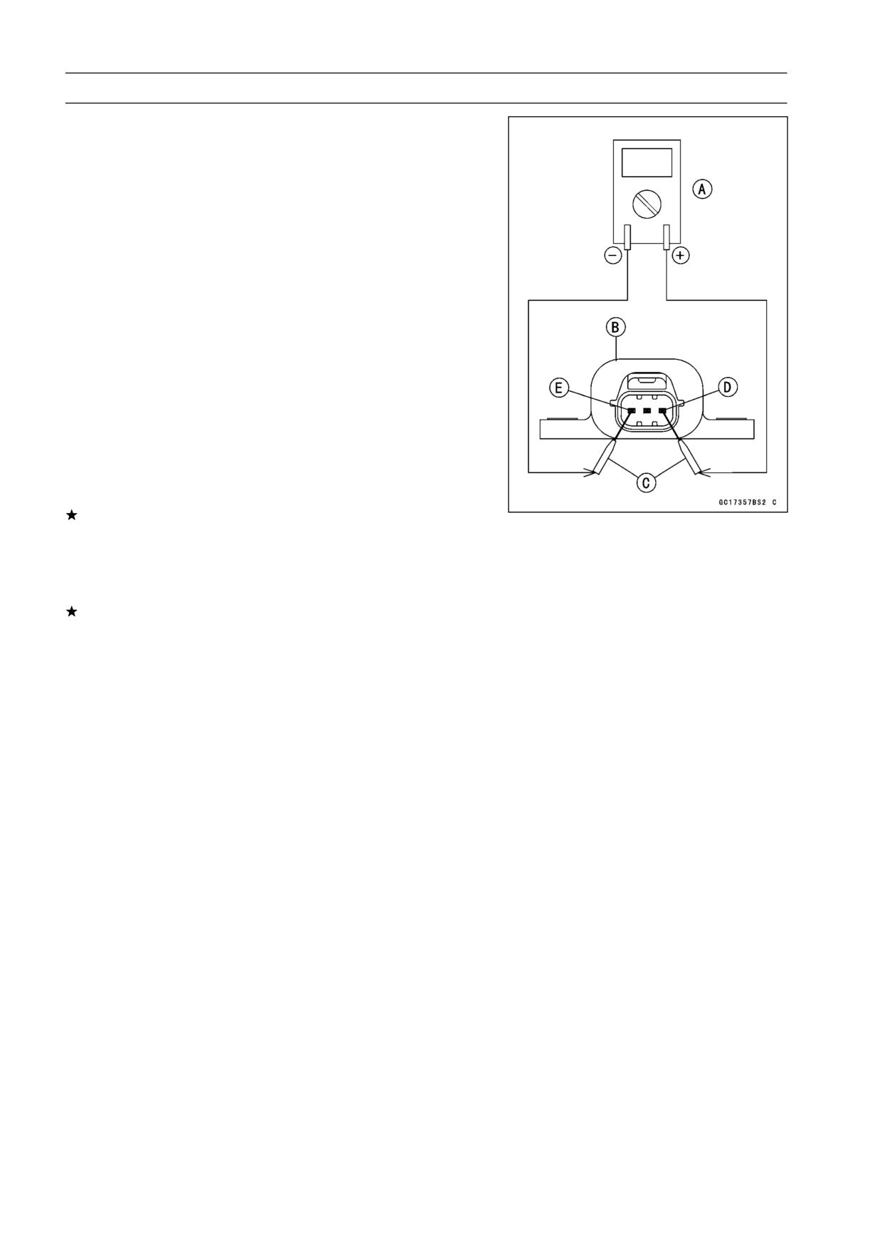
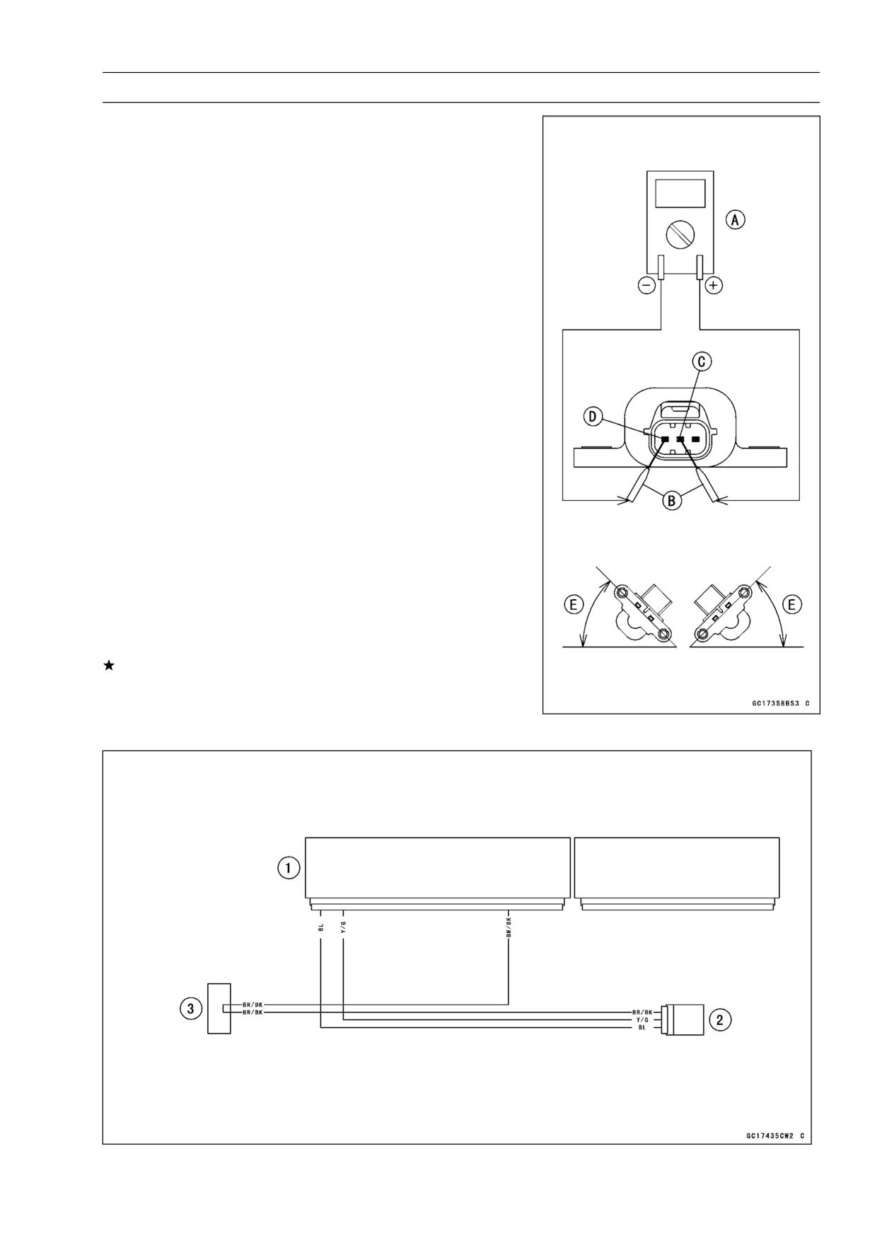
• Connect a digital meter [A] to the connector of the vehicle
-down sensor [B], with the needle adapter set [C].
Special Tool - Needle Adapter Set: 57001-1457
Vehicle-down sensor Power Source Voltage
Connections to Sensor
Meter (+) → BL lead [D]
Meter (-) → BR/BK lead [E]
• Turn the ignition switch ON, and measure the power
source voltage with the connector joined.
Power Source Voltage at Sensor
Standard: DC 4.75 ∼ 5.25 V
• Turn the ignition switch OFF.
If there is no voltage, check the following.
Battery (see Charging Condition Inspection in the Elec-
trical System chapter)
ECU Fuse 15 A (see Fuse Inspection in the Electrical
System chapter)
If the power source is normal, check the output voltage.
FUEL SYSTEM (DFI) 3-75
Vehicle-down Sensor (Service Code 31)
• Turn the ignition switch OFF.
• Remove the vehicle-down sensor.
○Do not disconnect the sensor connector.
• Connect a digital meter [A] to the connector, with needle
adapter set [B].
Special Tool - Needle Adapter Set: 57001-1457
Vehicle-down sensor Output Voltage
Connections to Sensor
Meter (+) → Y/G lead [C]
Meter (-) → BR/BK lead [D]
• Hold the sensor vertically.
• Turn the ignition switch ON, and measure the output volt-
age with the connector joined.
○Tilt the sensor 60 ∼ 70° or more [E] right or left, then hold
the sensor almost vertical with the arrow mark pointed up,
and measure the output voltage.
Output Voltage at Sensor
Standard: with sensor arrow mark pointed up: 3.55 ∼
4.45 V
with sensor tilted 60 ∼ 70° or more right or
left: 0.65 ∼ 1.35 V
NOTE
○If you need to test again, turn the ignition switch OFF,
and then ON.
• Turn the ignition switch OFF.
If the output voltage is out of the specified, replace the
vehicle-down sensor.
Vehicle-down Sensor Circuit
1. ECU
3. Water-proof Joint 2
2. Vehicle-down Sensor
3-76 FUEL SYSTEM (DFI)
Subthrottle Sensor (Service Code 32)
The subthrottle sensor is a rotating variable resistor that
change output voltage according to throttle operating. The
ECU senses this voltage change and determines fuel injec-
tion quantity, and ignition timing according to engine rpm,
and throttle opening.
Input Terminal [A]
Output Terminal [B]
Ground Terminal [C]
Subthrottle Sensor Removal/Adjustment
CAUTION
Do not remove or adjust the subthrottle sensor [A]
since it has been adjusted and set with precision at
the factory.
Never drop the throttle body assy, especially on a
hard surface. Such a shock to the sensor can dam-
age it.
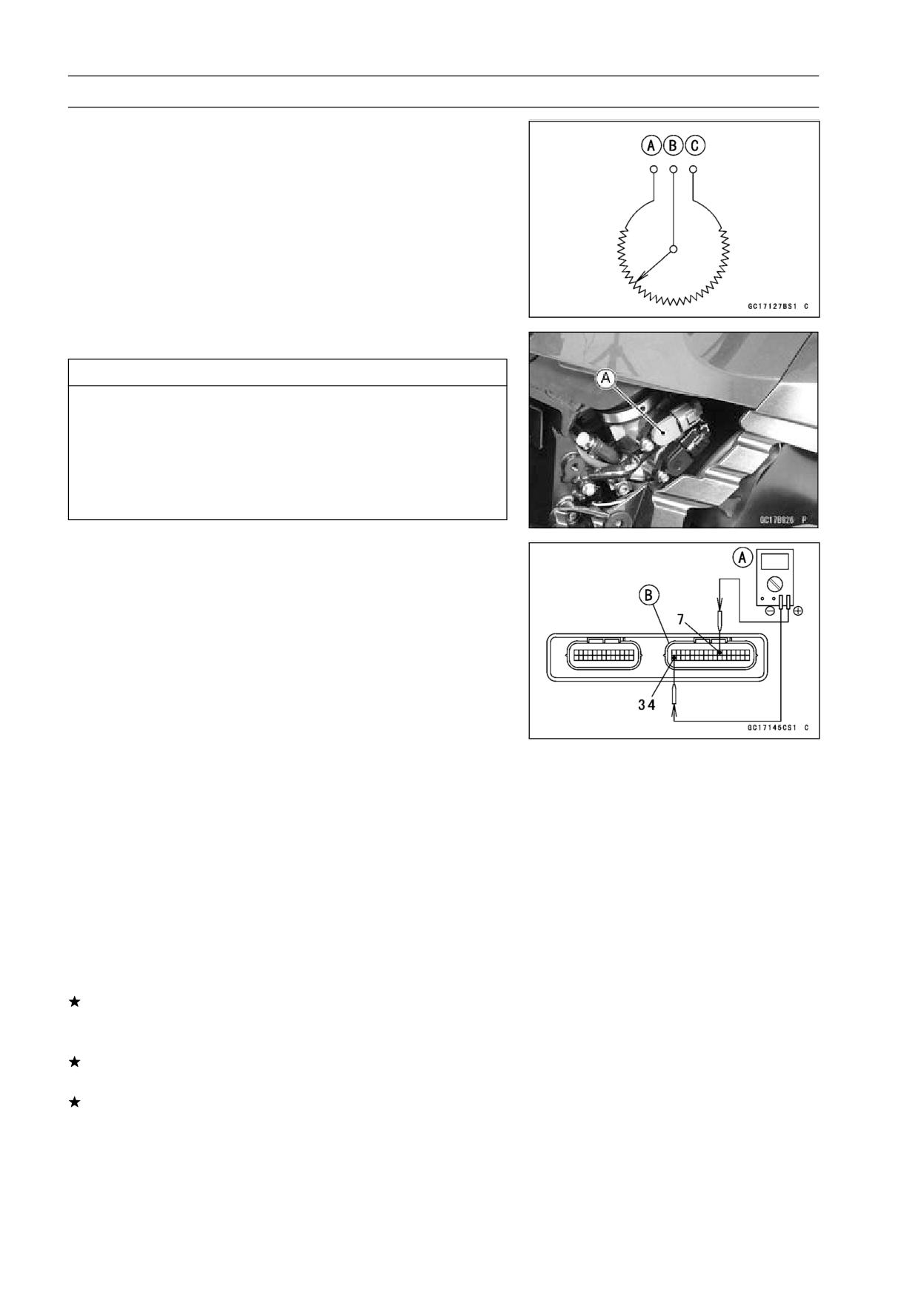
Input Voltage Inspection
NOTE
○Be sure the battery is fully charged.
• Turn the ignition switch OFF.
• Remove the ECU (see ECU Removal).
○Do not disconnect the ECU connectors.
• Connect a digital meter [A] to the connector [B], using the
needle adapter set.
Special Tool - Needle Adapter Set: 57001-1457
Subthrottle Sensor Input Voltage
Connections to ECU Connector
Meter (+) → BL lead (terminal 7)
Meter (-) → BR/BK lead (terminal 34)
• Measure the input voltage with the engine stopped, and
with the connectors joined.
• Turn the ignition switch ON.
Input Voltage at ECU Connector
Standard: DC 4.75 ∼ 5.25 V
• Turn the ignition switch OFF.
If the reading of input voltage is less than the standard,
check the ECU for its ground, power supply and wiring
shorted.
If the ground and power supply are good, replace the ECU
(see ECU section).
If the input voltage is within the standard range, check the
input voltage at the subthrottle sensor connector.
FUEL SYSTEM (DFI) 3-77
Subthrottle Sensor (Service Code 32)
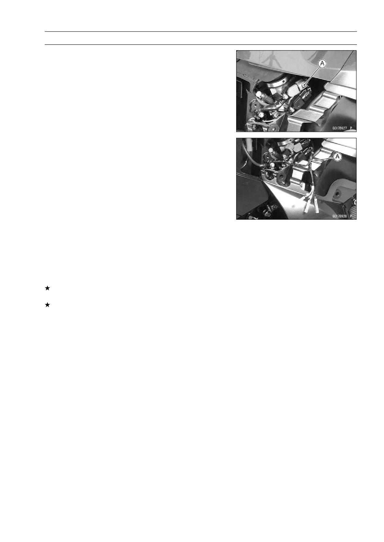
• Remove the right fairing cover (see Fairing Cover Re-
moval in the Frame chapter).
• Disconnect the subthrottle sensor connector [A].
• Connect the harness adapter [A] between the harness
connector and subthrottle sensor connector.
Special Tool - Throttle Sensor Setting Adapter:
57001
-1538
• Connect a digital meter to the harness adapter leads.
Subthrottle Sensor Input Voltage
Connections to Adapter
Meter (+) → BK (sensor BL) lead
Meter (-) → W (sensor BR/BK) lead
• Measure the sensor input voltage with the engine
stopped, and with the connector joined.
• Turn the ignition switch ON.
Input Voltage at Sensor
Standard: DC 4.75 ∼ 5.25 V
• Turn the ignition switch OFF.
If the reading is out of the range, check the wiring (see
wiring diagram in this section).
If the reading is good, check the output voltage of the
sensor.
3-78 FUEL SYSTEM (DFI)
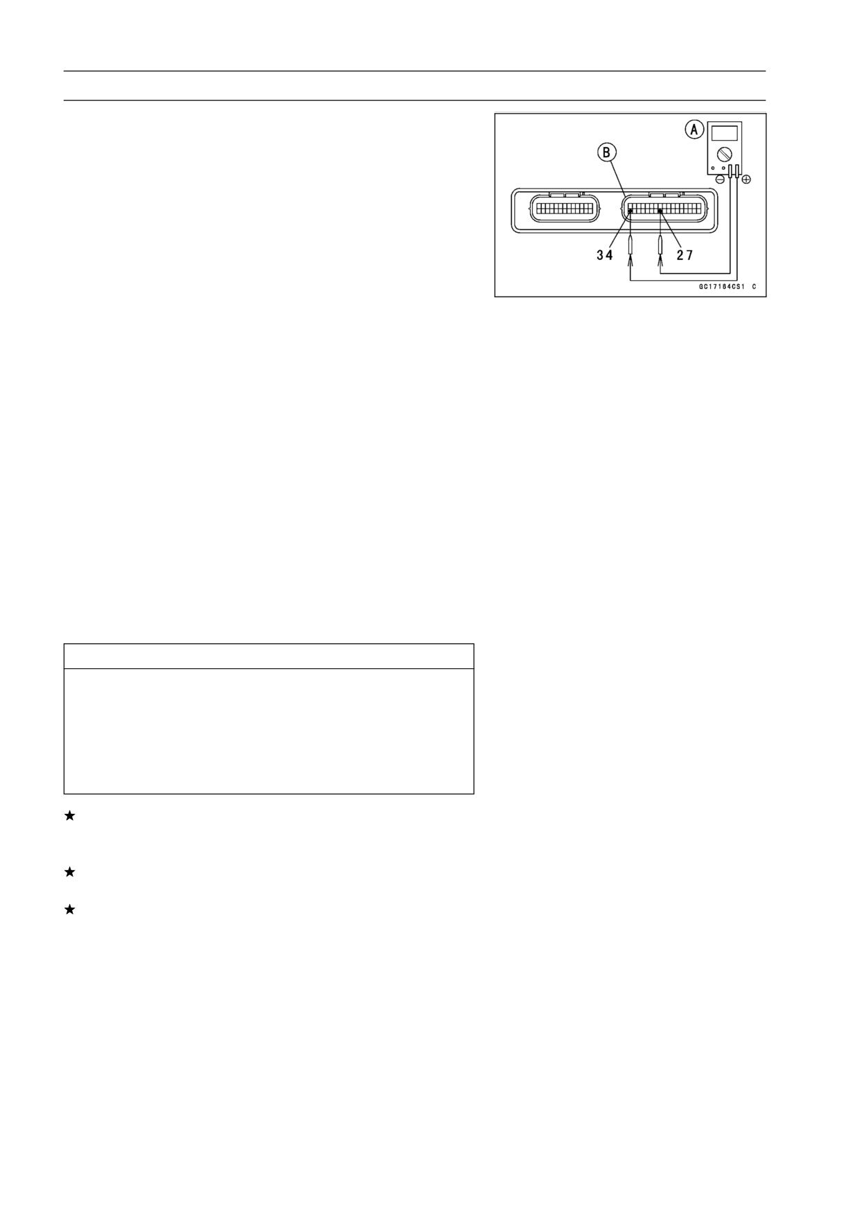
Subthrottle Sensor (Service Code 32)
Output Voltage Inspection
• Measure the output voltage at the ECU in the same way
as input voltage inspection. Note the following.
Digital Meter [A]
Connector [B]
Special Tool - Needle Adapter Set: 57001-1457
Subthrottle Sensor Output Voltage
Connections to ECU Connector
Meter (+) → BL/W lead (terminal 27)
Meter (-) → BR/BK lead (terminal 34)
• Remove the air cleaner caps (see Throttle Body Assy Re-
moval).
• Turn the ignition switch ON.
• Measure the output voltage when the subthrottle valve is
fully opened or completely closed by hand.
Output Voltage at ECU
Standard: DC 0.62 ∼ 4.14 V (at subthrottle valve full
opening to closing)
NOTE
○The throttle sensor is operating correctly if the following
voltages are obtained:
• DC 0.62 V (or slightly higher) with the subthrottle valve
at the closed position.
• DC 4.14 V (or slightly lower) with the subthrottle valve
at the fully open position.
CAUTION
Do not remove or adjust the subthrottle sensor. It
has been adjusted and set with precision at the fac-
tory.
Never drop the throttle body assy, especially on a
hard surface. Such a shock to the sensor can dam-
age it.
If the output voltage is within the standard range, check
the ECU for its ground, and power supply (see ECU
Power Supply Inspection).
If the ground and power supply are good, replace the ECU
(see ECU Removal).
If the output voltage is far out of the standard range (e.g.
when the wiring is open, the reading is 0 V), check the
output voltage again at the sensor connector.
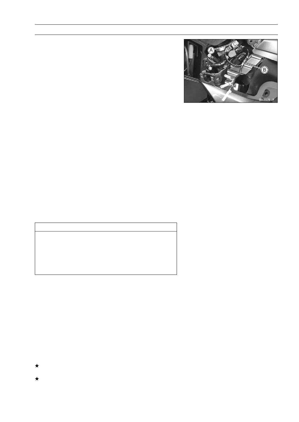
FUEL SYSTEM (DFI) 3-79
Subthrottle Sensor (Service Code 32)
• Disconnect the subthrottle sensor connector [A] and con-
nect the harness adapter [B] between the harness con-
nector and subthrottle sensor connector.
Special Tool - Throttle Sensor Harness Adapter:
57001
-1538
• Connect a digital meter to the harness adapter leads.
Subthrottle Sensor Output Voltage
Connections to Adapter
Meter (+) → R (sensor BL/W) lead
Meter (-) → W (sensor BR/BK) lead
• Measure the output voltage with the engine stopped, and
with the connector joined.
• Turn the ignition switch ON.
• Measure the output voltage when the subthrottle valve is
fully opened or completely closed by hand.
Output Voltage at Sensor
Standard: DC 0.62 ∼ 4.14 V (at subthrottle valve full
opening to closing)
NOTE
○The throttle sensor is operating correctly if the following
voltages are obtained:
• DC 0.62 V (or slightly higher) with the subthrottle valve
at the closed position.
• DC 4.14 V (or slightly lower) with the subthrottle valve
at the fully open position.
CAUTION
Do not remove or adjust the subthrottle sensor. It
has been adjusted and set with precision at the fac-
tory.
Never drop the throttle body assy, especially on a
hard surface. Such a shock to the sensor can dam-
age it.
NOTE
○The standard voltage refers to the value when the volt-
age reading at the Input Voltage Inspection shows 5V
exactly.
○When the input voltage reading shows other than 5V,
derive a voltage range as follows.
Example:
In the case of a input voltage of 4.75 V.
0.62 × 4.75 ÷ 5.00 = 0.59 V
4.14 × 4.75 ÷ 5.00 = 3.93 V
Thus, the valid range is 0.59 ∼ 3.93 V
• Turn the ignition switch OFF.
If the reading is out of the standard range, inspect the
subthrottle sensor resistance.
If the output voltage is normal, check the wiring for conti-
nuity (see wiring diagram in this section).
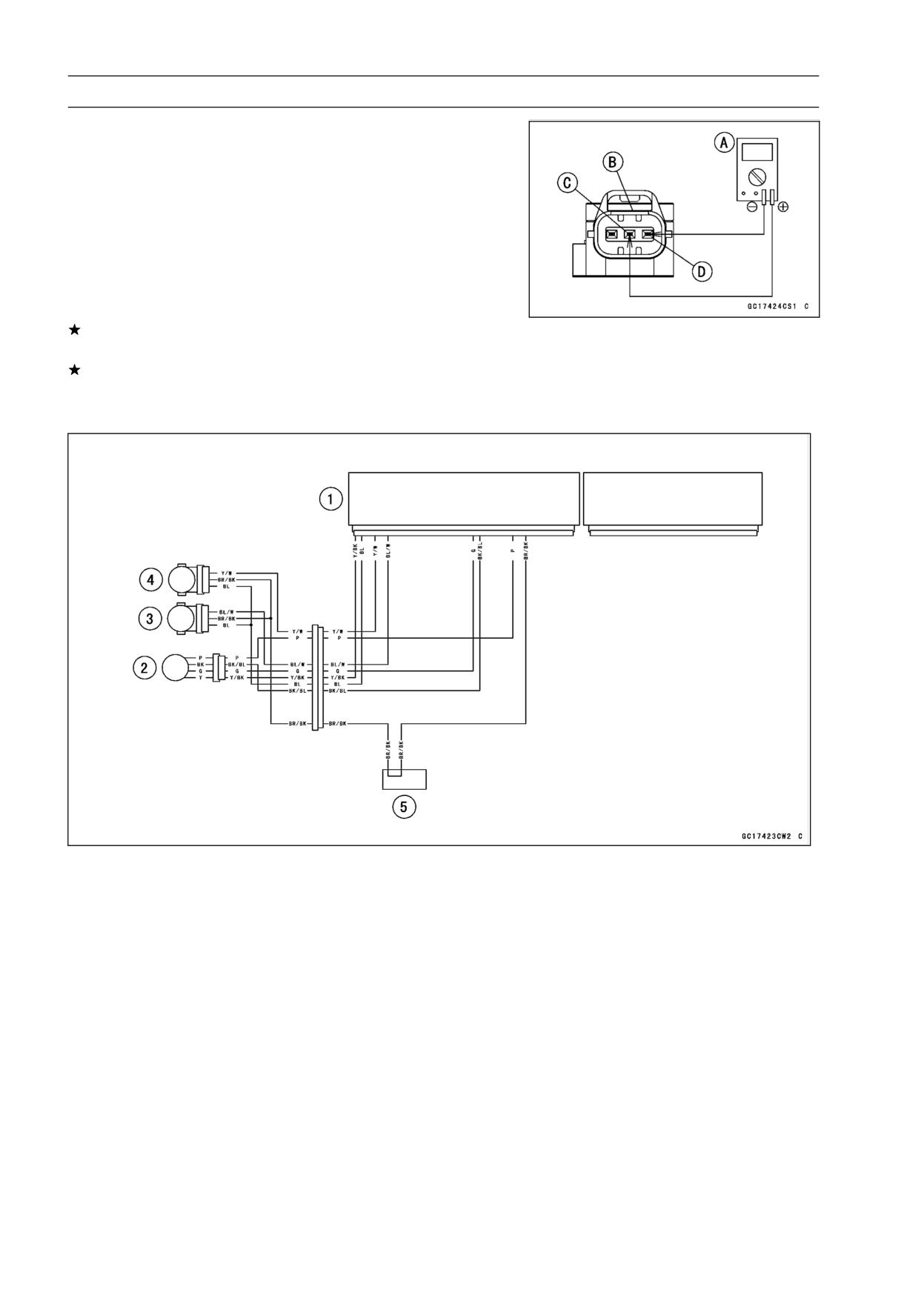
3-80 FUEL SYSTEM (DFI)
Subthrottle Sensor (Service Code 32)
Resistance Inspection
• Turn the ignition switch OFF.
• Disconnect the subthrottle sensor connector.
• Connect a digital meter [A] to the subthrottle sensor con-
nector [B].
• Measure the subthrottle sensor resistance.
Subthrottle Sensor Resistance
Connections: BL lead [C] ←→ BR/BK lead [D]
Standard:
4 ∼ 6 kΩ
If the reading is out of the range, replace the throttle body
assy (see Throttle Body Assy section).
If the reading is within the range, but the problem still
exists, replace the ECU (see ECU section).
Subthrottle Sensor Circuit
1. ECU
2. Subthrottle Valve Actuator
3. Subthrottle Sensor
4. Main Throttle Sensor
5. Water-proof Joint 2
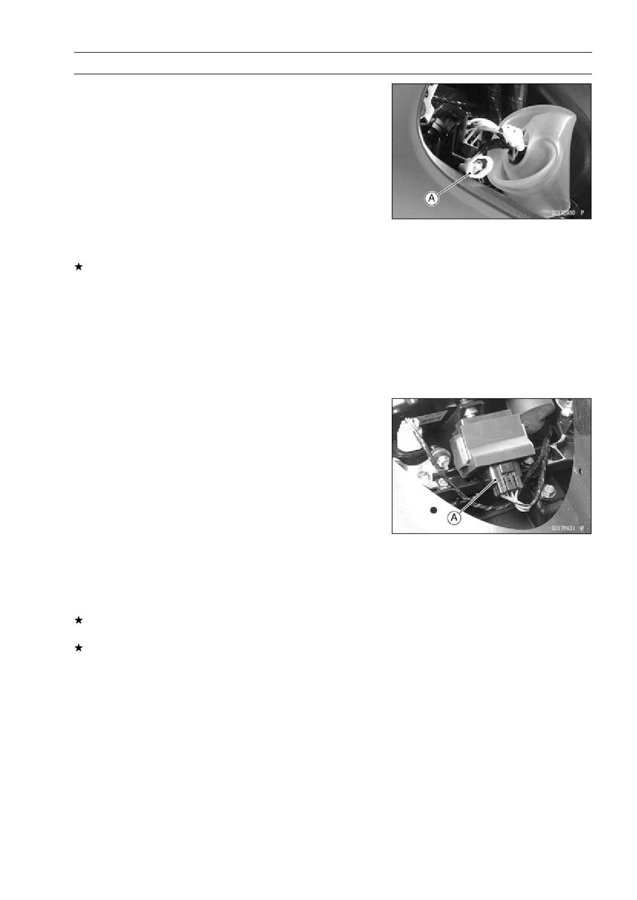
FUEL SYSTEM (DFI) 3-81
Immobilizer Amplifier (Service Code 35)
Antenna Resistance Inspection
• Remove the left inner cover (see Inner Cover Removal in
the Frame chapter).
• Disconnect the antenna lead connector [A].
• Measure the resistance of the antenna coil in the ignition
switch as follows.
Antenna Resistance
Connections to Antenna
Meter → BK lead
Meter → BK lead
Standard: About 0.6 ∼ 0.9 Ω
If the resistance is out of the standard range, replace the
ignition switch.
Amplifier Input Voltage Inspection
NOTE
○Be sure the battery is fully charged.
• Turn the ignition switch OFF.
• Remove the windshield (see Windshield Removal in the
Frame chapter).
• Connect a digital meter to the amplifier connector [A], us-
ing the needle adapter set.
Special Tool - Needle Adapter Set: 57001-1457
Amplifier Input Voltage
Connections to Connector
Meter (+) → BR/W lead
Meter (-) → BK/Y lead
• Measure the input voltage with the engine stopped, and
with the connector joined.
• Turn the ignition switch ON.
Input Voltage
Standard: Battery Voltage
• Turn the ignition switch OFF.
If the reading is out of the range, check the wiring (see
wiring diagram in next section).
If the reading and antenna resistance are good, replace
the amplifier (see Immobilizer System Parts Replacement
in the Electrical System chapter).
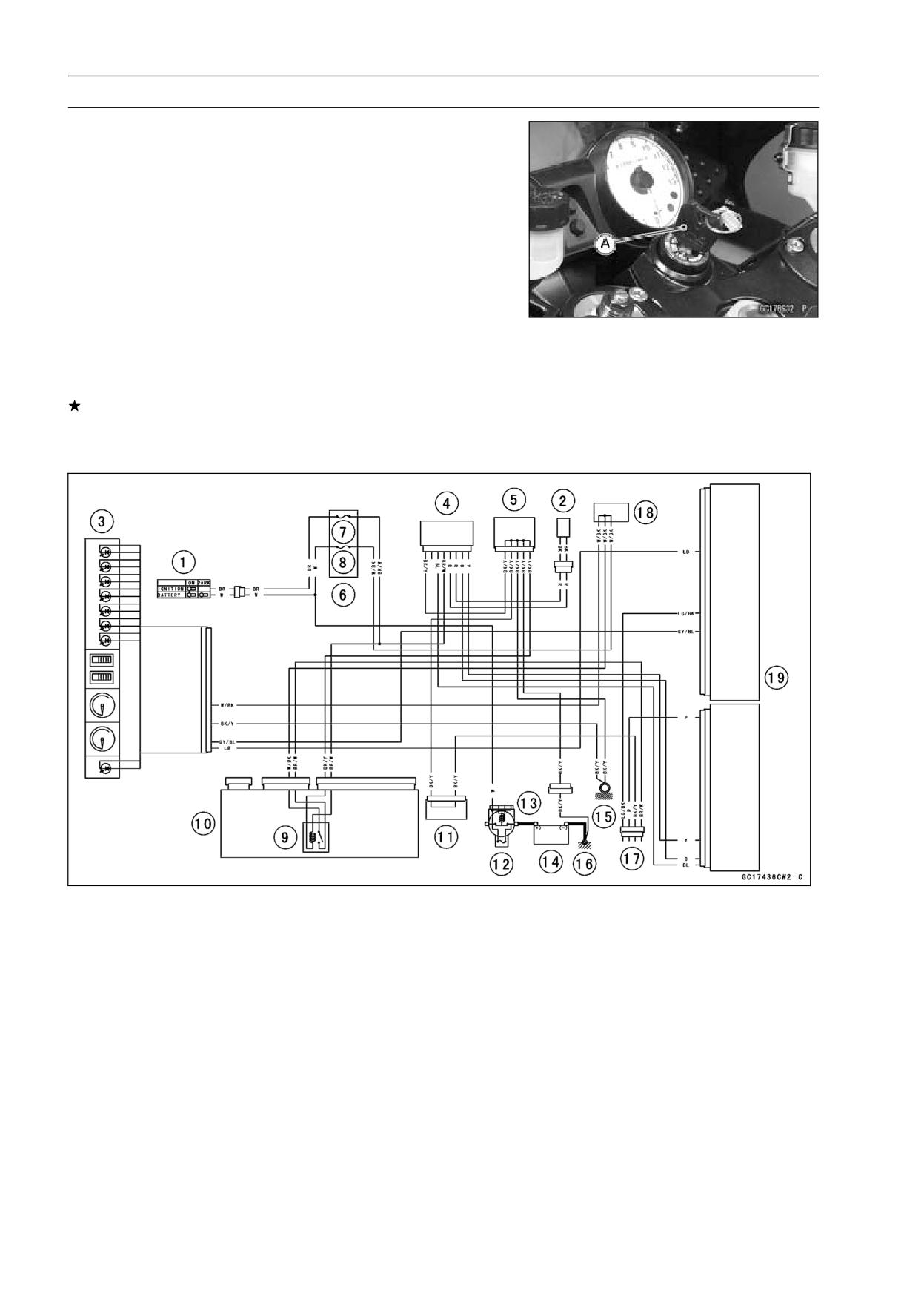
3-82 FUEL SYSTEM (DFI)
Blank Key Detection (Service Code 36)
• This code appears in the following conditions.
○The transponder [A] in the master and/or user key is mal-
function.
○When the spare key of unregistration is used.
○When the master key is registered in the registered ECU.
• Therefore, the service code 36 will disappear when the
above issue is solved.
User Key Inspection
• Register the user key correctly (see Key Registration in
the Electrical System chapter).
If the service code 36 appears again, the transponder in
the key is malfunction, replace it.
Immobilizer System Circuit
1. Ignition Switch
10. Relay Box
2. Immobilizer Antenna
11. Joint Connector 2
3. Meter Unit
12. Main Fuse 30 A
4. Immobilizer Amplifier
13. Starter Relay
5. Joint Connector 1
14. Battery 12 V 14 Ah
6. Fuse Box × 2
15. Frame Ground 1
7. ECU Fuse 15 A
16. Frame Ground 2
8. Ignition Fuse 10 A
17. Immobilizer/Kawasaki Diagnostic System
9. Main Relay
Connector
18. Water-proof Joint 1
19. ECU
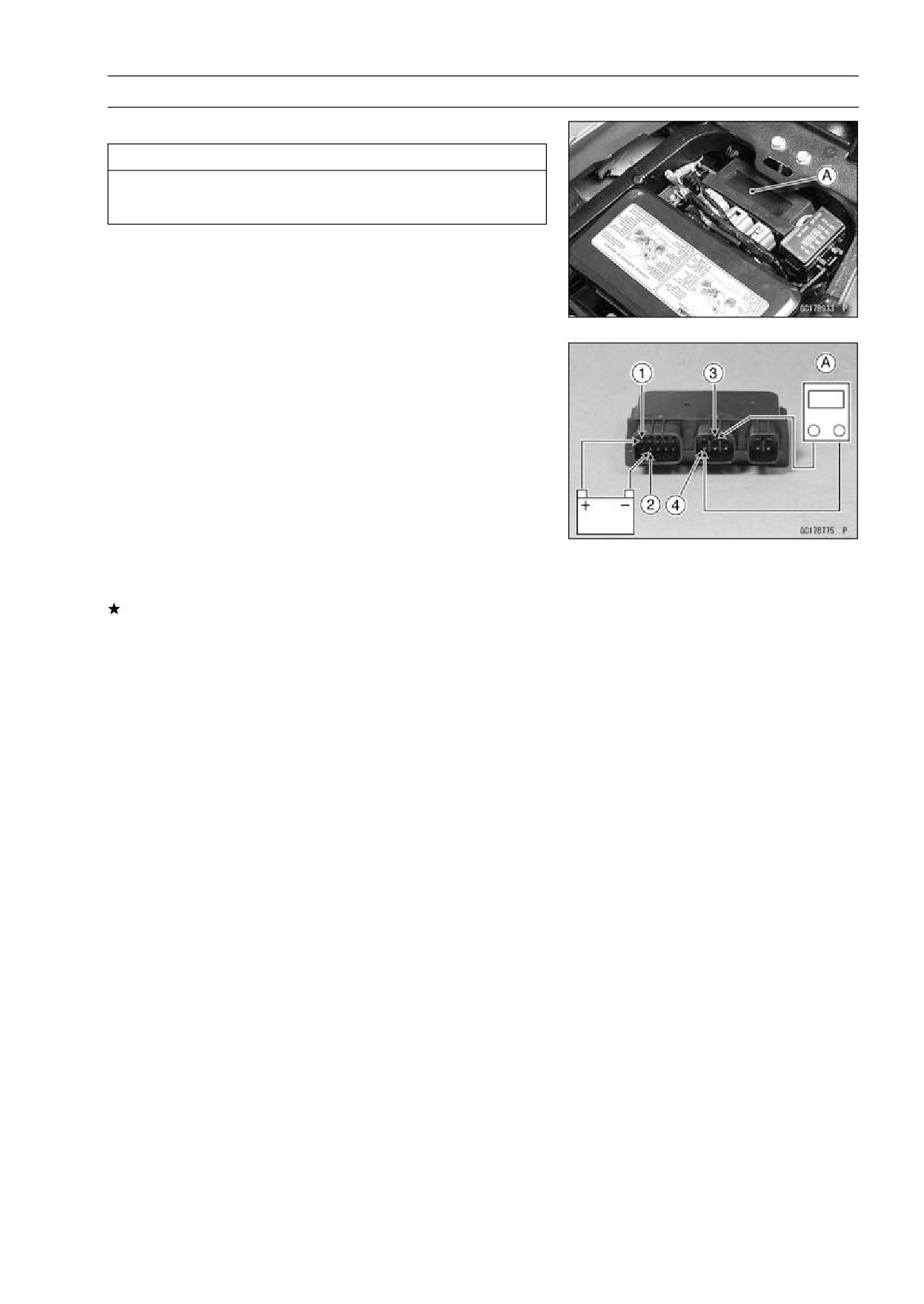
FUEL SYSTEM (DFI) 3-83
Fuel Pump Relay (Service Code 46)
Fuel Pump Relay Removal
CAUTION
Never drop the relay, especially on a hard surface.
Such a shock to the relay can damage it.
○The fuel pump relay is included in the relay box.
• Remove the seat (see Seat Removal in the Frame chap-
ter).
• Remove the relay box [A] from the bracket and disconnect
the connectors.
Fuel Pump Relay Inspection
• Remove the relay box (see Fuel Pump Relay Removal).
• Connect the hand tester [A] and one 12 V battery to the
relay connector as shown.
Special Tool - Hand Tester: 57001-1394
Relay Coil Terminals [1] and [2]
Relay Switch Terminals [3] and [4]
Testing Relay
Tester range:
1 Ω range
Criteria:
When battery is connected → 0 Ω
When battery is disconnected → ∞ Ω
If the relay does not work as specified, replace the relay
box.
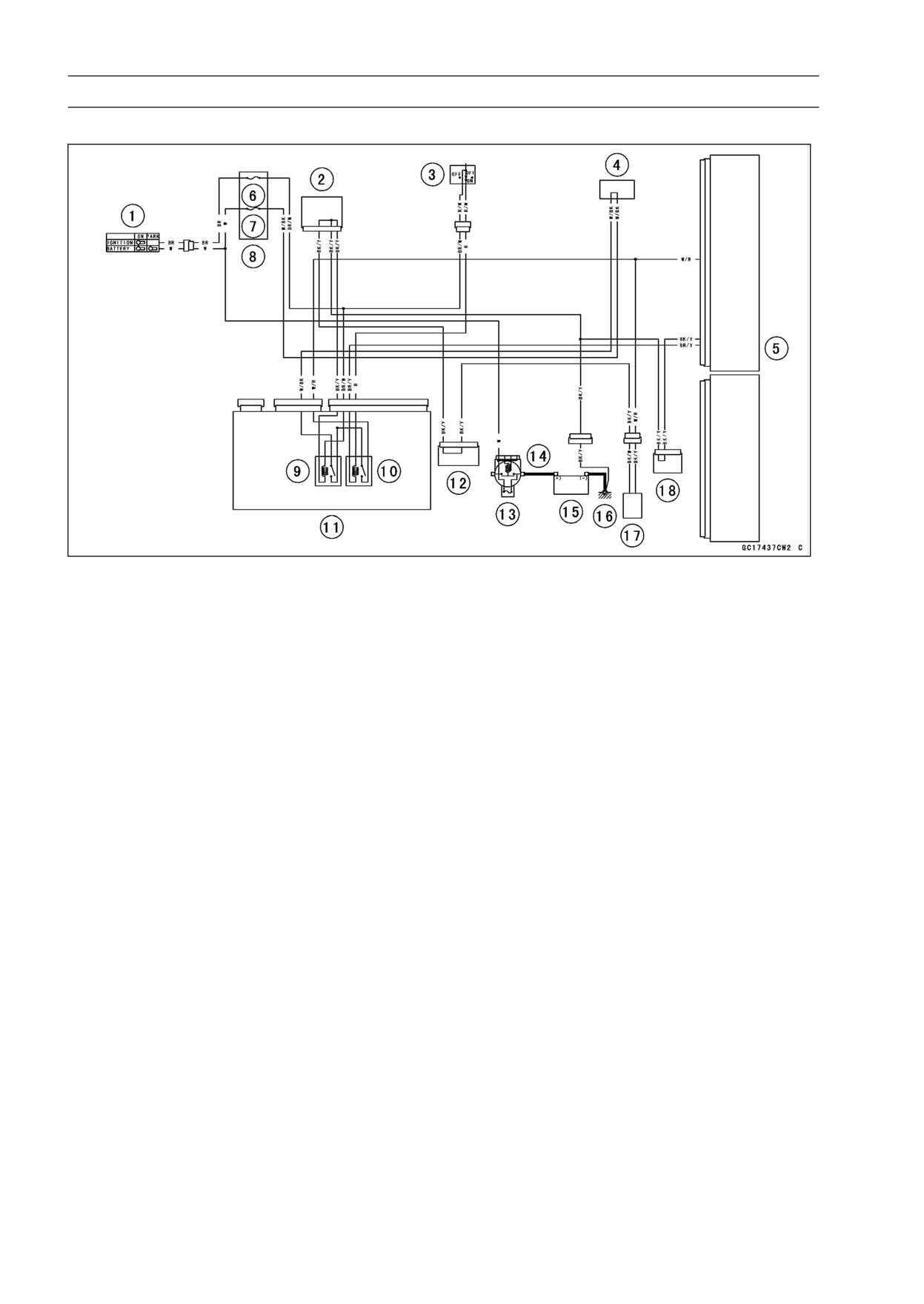
3-84 FUEL SYSTEM (DFI)
Fuel Pump Relay (Service Code 46)
Fuel Pump Relay Circuit
1. Ignition Switch
10. Fuel Pump Relay
2. Joint Connector 1
11. Relay Box
3. Engine Stop Switch
12. Joint Connector 2
4. Water-proof Joint 1
13. Main Fuse 30 A
5. ECU
14. Starter Relay
6. ECU Fuse 15 A
15. Battery 12 V 14 Ah
7. Ignition Fuse 10 A
16. Frame Ground 2
8. Fuse Box 2
17. Fuel Pump
9. Main Relay
18. Joint Connector 3
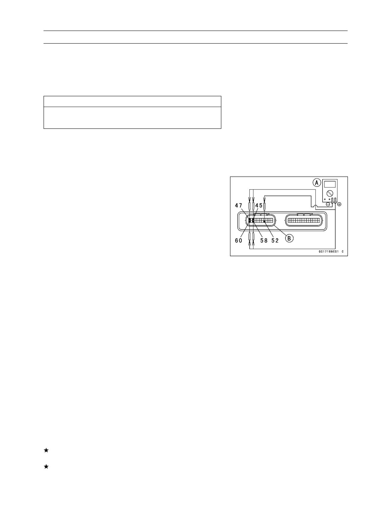
FUEL SYSTEM (DFI) 3-85
Stick Coils #1, #2, #3, #4: (Service Code 51, 52, 53, 54)
Stick Coil #1: Service Code 51
Stick Coil #2: Service Code 52
Stick Coil #3: Service Code 53
Stick Coil #4: Service Code 54
Removal/Installation
CAUTION
Never drop the stick coils, especially on a hard sur-
face. Such a shock to the stick coil can damage it.
• Refer to the Stick Coil (Ignition Coil together with Spark
Plug Cap) Removal/Installation in the Electrical System
chapter (see Stick Coil (Ignition Coil together with Spark
Plug Cap) Removal/Installation in the Electrical System
chapter).
Input Voltage Inspection
NOTE
○Be sure the battery is fully charged.
• Turn the ignition switch OFF.
• Remove the ECU (see ECU Removal).
○Do not disconnect the ECU connectors.
• Connect a digital meter [A] as shown, with the needle
adapter set.
Special Tool - Needle Adapter Set: 57001-1457
Stick Coil Input Voltage at ECU
Connections for Stick Coil #1
Meter (+) → W/R lead (terminal 47)
Meter (-) → BK/Y lead (terminal 52)
Connections for Stick Coil #2
Meter (+) → W/BL lead (terminal 60)
Meter (-) → BK/Y lead (terminal 52)
Connections for Stick Coil #3
Meter (+) → W/G lead (terminal 45)
Meter (-) → BK/Y lead (terminal 52)
Connections for Stick Coil #4
Meter (+) → W/Y lead (terminal 58)
Meter (-) → BK/Y lead (terminal 52)
• Measure the input voltage to each primary winding of the
stick coils with the engine stopped, and with the connec-
tors joined.
• Turn the ignition switch ON.
Input Voltage at ECU
Standard: Battery Voltage
If the reading is out of the standard, check the wiring (see
wiring diagram in this section).
If the reading is good, the input voltage is normal. Crank
the engine, and check the peak voltage of the stick coils
(see Stick Coil Primary Peak Voltage Inspection in the
Electrical System chapter) in order to check the primary
coils.
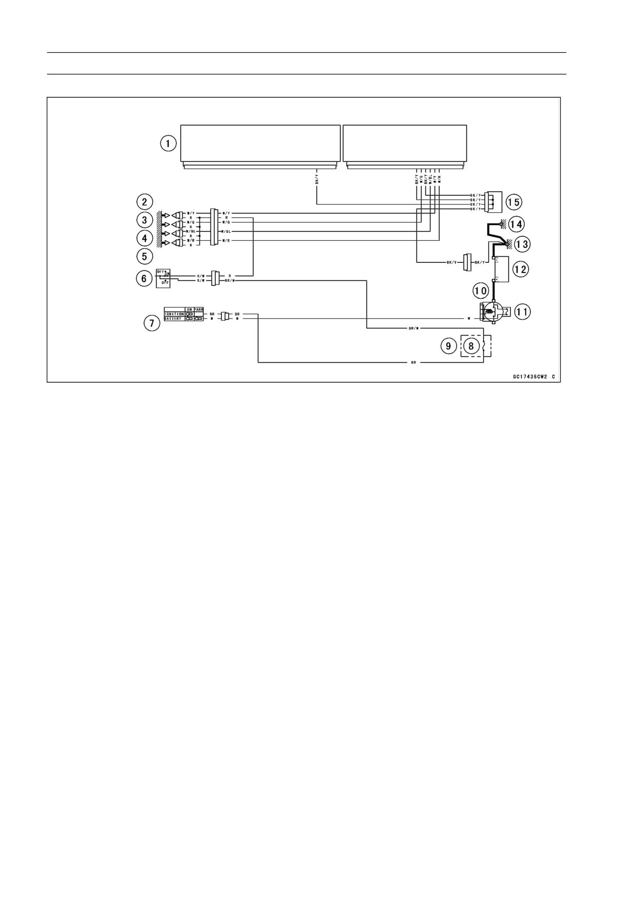
3-86 FUEL SYSTEM (DFI)
Stick Coils #1, #2, #3, #4: (Service Code 51, 52, 53, 54)
Stick Coil Circuit
1. ECU
9. Ignition Fuse 10 A
2. Stick Coil #4
10. Starter Relay
3. Stick Coil #3
11. Main Fuse 30 A
4. Stick Coil #2
12. Battery 12 V 14 Ah
5. Stick Coil #1
13. Frame Ground 2
6. Engine Stop Switch
14. Engine Ground
7. Ignition Switch
15. Joint Connector 3
8. Fuse Box 2
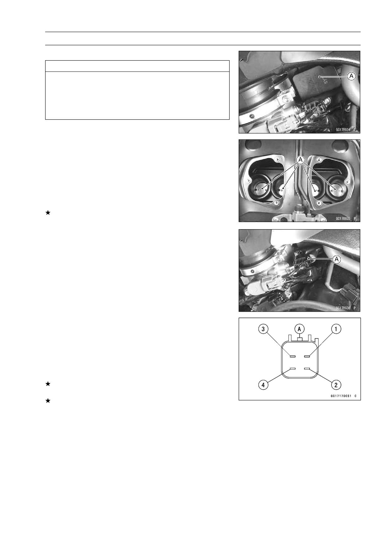
FUEL SYSTEM (DFI) 3-87
Subthrottle Valve Actuator (Service Code 62)
Subthrottle Valve Actuator Removal
CAUTION
Do not remove the subthrottle valve actuator [A]
since it has been adjusted and set with precision
at the factory.
Never drop the actuator , especially on a hard sur-
face. Such a shock to the actuator can damage it.
Subthrottle Valve Actuator Inspection
• Remove:
Fuel Tank (see Fuel Tank Removal)
Left and Right Air Cleaner Caps (see Throttle Body Assy
Removal)
• Turn the ignition switch ON.
• Check to see that all subthrottle valves [A] open and close
smoothly.
If the subthrottle valves do not operate, check the actuator
internal resistance (see Resistance Inspection).
Resistance Inspection
• Turn the ignition switch OFF.
• Disconnect the subthrottle valve actuator connector [A].
• Connect a digital meter to the connector [A].
• Measure the subthrottle valve actuator resistance.
Subthrottle Valve Actuator Resistance
Connections: Y lead [1] ←→ P lead [2]
BK lead [3] ←→ G lead [4]
Standard:
About 5 ∼ 7 Ω
If the reading is out of the range, replace the throttle body
assy (see Throttle Body Assy section).
If the reading is within the range, check the input voltage
(see Input Voltage Inspection in this section).
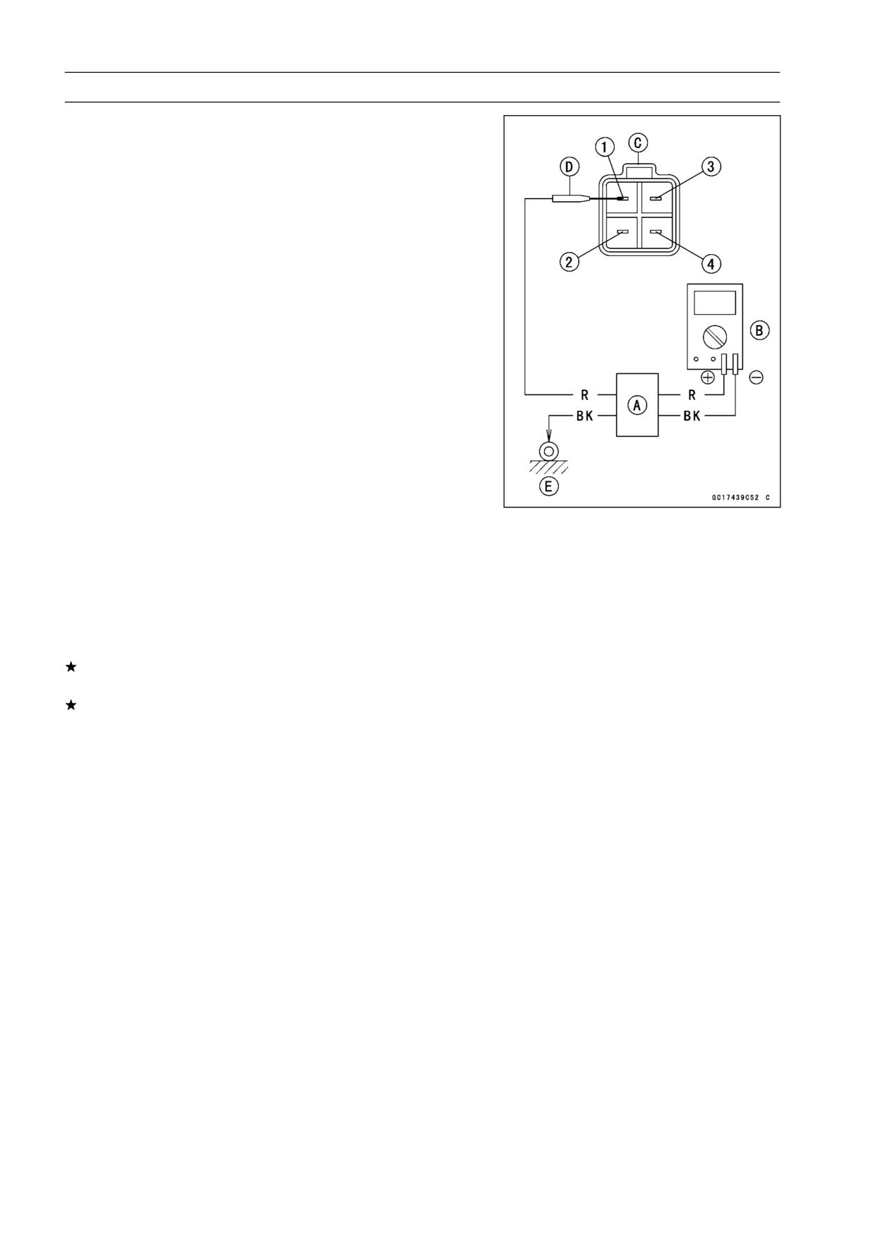
3-88 FUEL SYSTEM (DFI)
Subthrottle Valve Actuator (Service Code 62)
Input Voltage Inspection
NOTE
○Be sure the battery is fully charged.
• Turn the ignition switch OFF.
• Connect the peak voltage adapter [A] and a digital meter
[B] to the connector [C], using the needle adapter set [D].
Special Tools - Peak Voltage Adapter: 57001-1415
Type: KEK-54-9-B
Needle Adapter Set: 57001-1457
Subthrottle Valve Actuator Input Voltage
Connections to Harness Connector
(I)
Meter (+) → BK/BL lead [1]
Meter (-) → Frame Ground 2 [E]
(II) Meter (+) → G lead [2]
Meter (-) → Frame Ground 2 [E]
(III) Meter (+) → Y/BK lead [3]
Meter (-) → Frame Ground 2 [E]
(IV) Meter (+) → P lead [4]
Meter (-) → Frame Ground 2 [E]
• Measure the input voltage with the engine stopped, and
with the connector joined.
• Turn the ignition switch ON.
Input Voltage
Standard: About DC 10.5 ∼ 12.5 V
If the reading is out of the range, check the wiring to ECU
(see wiring diagram in this section).
If the wiring is good, replace the ECU (see ECU section).
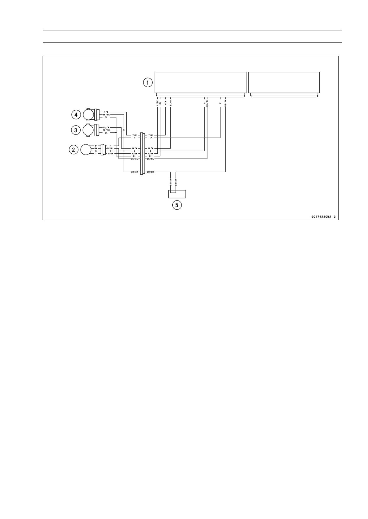
FUEL SYSTEM (DFI) 3-89
Subthrottle Valve Actuator (Service Code 62)
Subthrottle Valve Actuator Circuit
1. ECU
2. Subthrottle Valve Actuator
3. Subthrottle Sensor
4. Main Throttle Sensor
5. Water-proof Joint 2
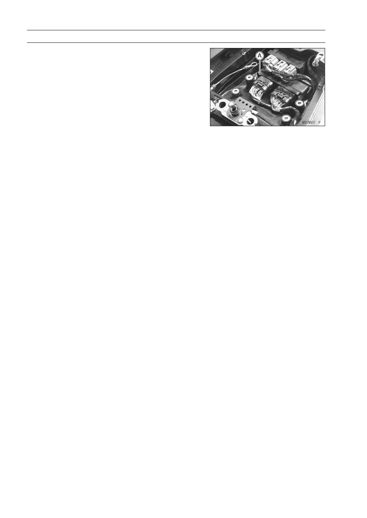
3-90 FUEL SYSTEM (DFI)
ECU Main Relay (Service Code 75)
ECU Main Relay Inspection
○The ECU main relay function is included in the ECU [A].
So, the ECU main relay function cannot be inspected.
• When the service code 75 is displayed on the LCD, re-
place the ECU (see ECU section).
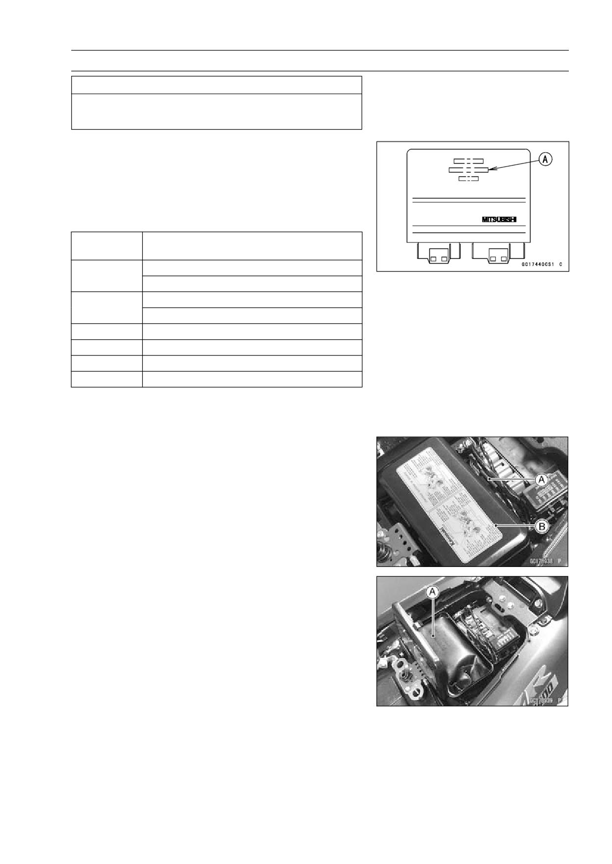
FUEL SYSTEM (DFI) 3-91
ECU
CAUTION
Never drop the ECU, especially on a hard surface.
Such a shock to the ECU can damage it.
ECU Identification
○Most countries have their own regulations, so each ECU
has different characteristic. So, do not confuse ECU with
each other and use only the ECU for your model. Other-
wise, the motorcycle cannot clear the regulation.
ECU Identification
Part Number
Specification
[A]
Europe, WVTA, Full, H, with Immobilizer
21175-0076
U.K., WVTA, Full, H, with Immobilizer
U.S.A (except California), without Immobilizer
21175-0084
Canada, without Immobilizer
21175-0089
U.S.A (California), without Immobilizer
21175-0101
Malaysia, with Immobilizer
21175-0090
Australia, with Immobilizer
21175-0102
France, WVTA, 78.2, H, with Immobilizer
Full: Full Power
H: Honeycomb Type Catalyst
78.2: Maximum Horsepower 78.2 kW (106.3 PS)
ECU Removal
• Remove the seat (see Seat Removal in the Frame chap-
ter).
• Pull the hook [A] to lift up the lid [B] of the tool kit case.
• Remove the tool kit [A].
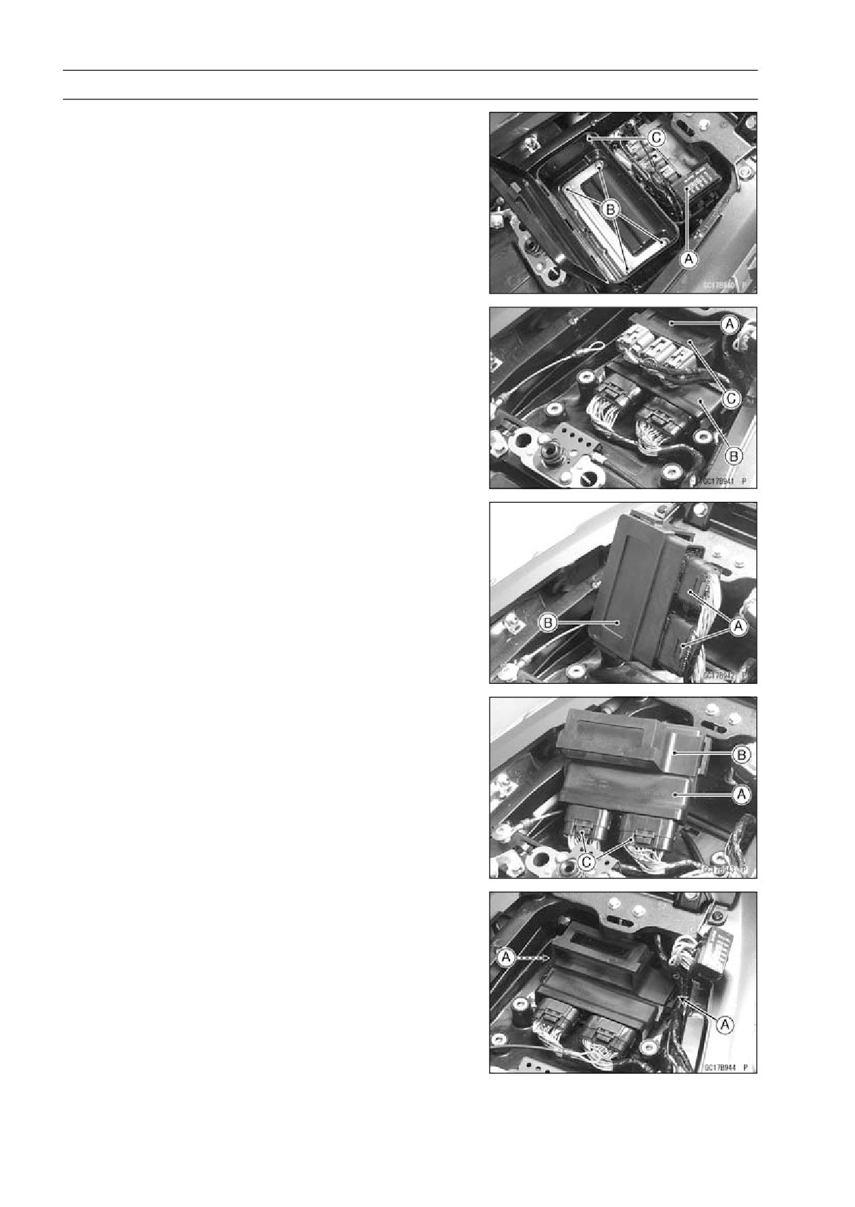
3-92 FUEL SYSTEM (DFI)
ECU
• Remove:
Fuse Box [A]
Bolts [B]
Tool Kit Case [C]
• Remove the relay box [A].
• Lift up the ECU [B] with rubber protector [C].
• Remove:
ECU Connectors [A]
ECU [B]
• Refer to the Immobilizer System Parts Replacement in the
Electrical System chapter for the immobilizer models (see
Immobilizer System Parts Replacement in the Electrical
System chapter).
ECU Installation
• Install:
ECU [A] (In rubber protector [B])
ECU Connectors [C]
• Insert the slits of the rubber protector to the projections
[A] of the rear fender front.
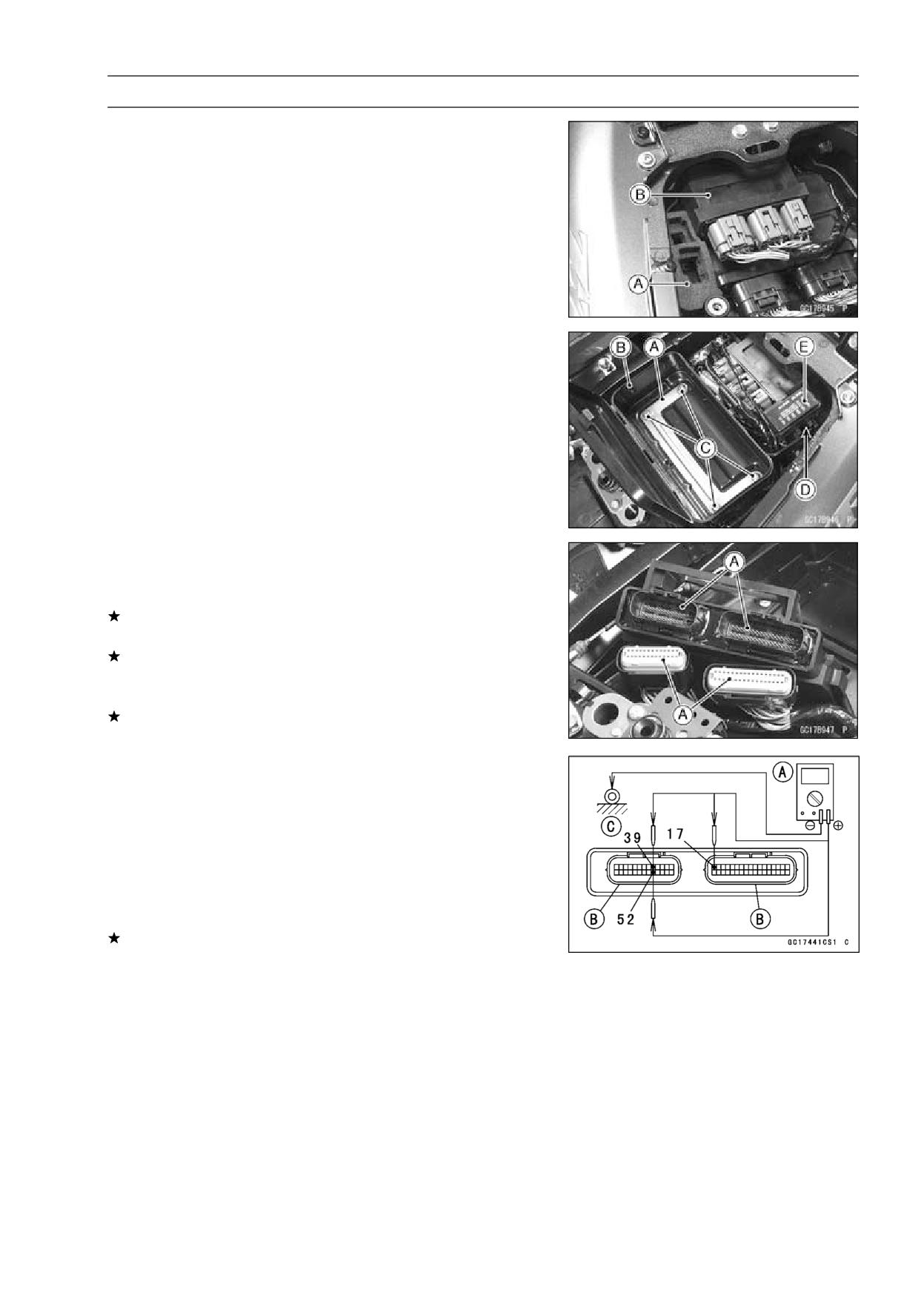
FUEL SYSTEM (DFI) 3-93
ECU
• Install:
Connector Holder [A]
Relay Box [B]
• Install the plate [A] to the tool kit case [B] and tighten the
bolts [C].
• Insert the stopper [D] of the fuse box [E] into the groove
of the tool case.
ECU Power Supply Inspection
• Remove the ECU (see ECU Removal).
• Visually inspect the terminals [A] of the ECU connectors.
If the connector is clogged with mud or dust, blow it off
with compressed air.
Replace the main harness if the terminals of the main
harness connectors are cracked, bent, or otherwise dam-
aged.
Replace the ECU if the terminals of the ECU connectors
are cracked, bent, or otherwise damaged.
• With the ECU connectors [B] connected, check the fol-
lowing ground lead for continuity with the ignition switch
OFF, using a digital meter [A] and needle adapter set.
Special Tool - Needle Adapter Set: 57001-1457
ECU Grounding Inspection
17, 39, or 52 Terminal
←→ Frame Ground 2 [C]: 0 Ω
Engine Ground
←→ Frame Ground 2 [C]: 0 Ω
If no continuity, check the connector, the engine ground
lead, or main harness, and repair or replace them if nec-
essary.
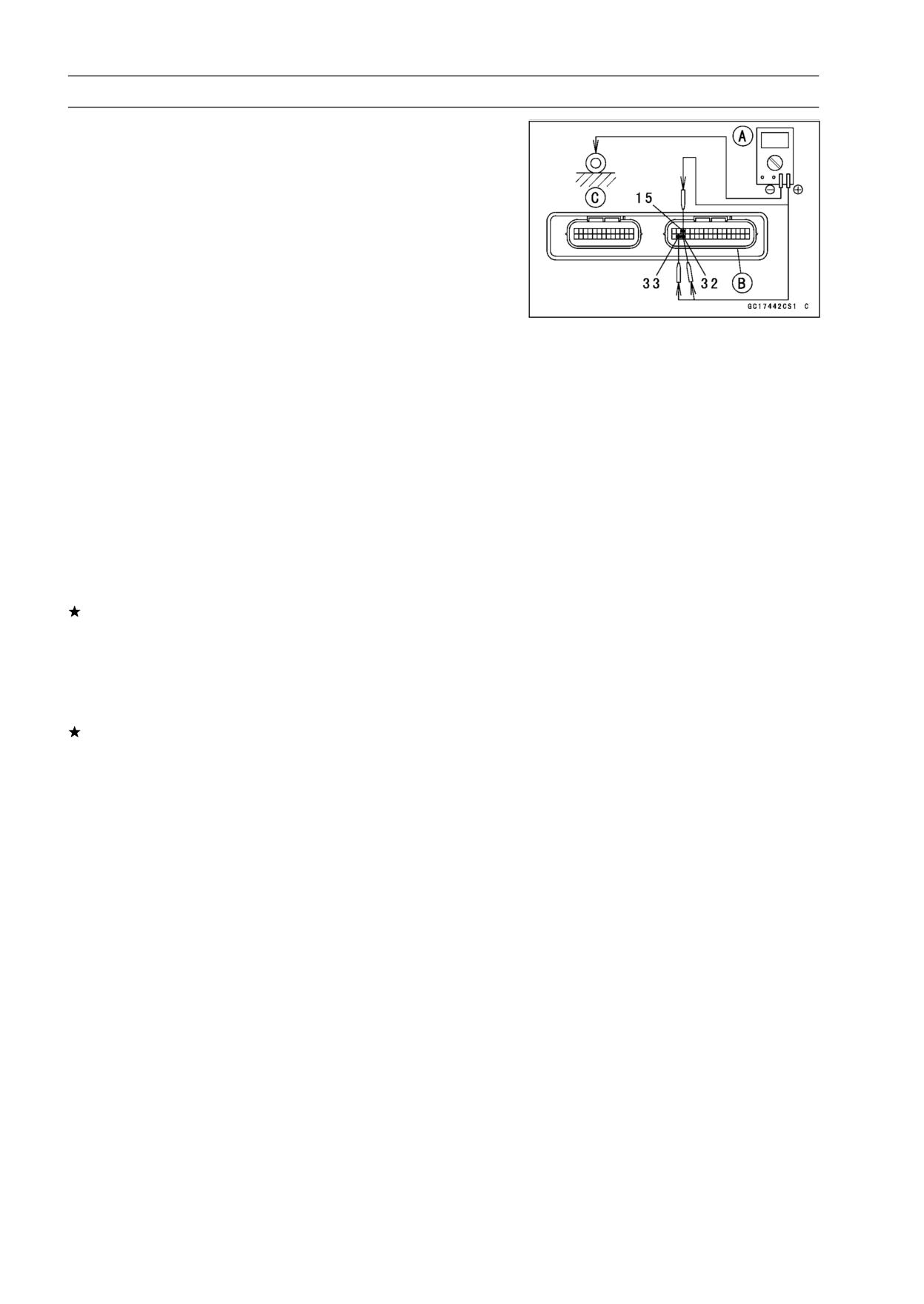
3-94 FUEL SYSTEM (DFI)
ECU
• Check the ECU power source voltage with a digital meter
[A].
○Position the terminal in accordance with terminal numbers
of ECU connectors [B] in the figure.
ECU Power Source Inspection
Tester
Connections:
between 33 (BR) Terminal and
Frame Ground 2 [C]
between 15 (W/BK) Terminal and
Frame Ground 2 [C]
between 32 (W/BK) and Frame
Ground 2 [C]
Ignition Switch OFF:
33 (BR) Terminal, 0 V
15 (W/BK) Terminal, Battery
Voltage
32 (W/BK) Terminal, Battery
Voltage
Ignition Switch ON:
33 (BR) Terminal, Battery Voltage
15 (W/BK) Terminal, Battery
Voltage
32 (W/BK) Terminal, Battery
Voltage
If the tester does not read as specified, check the follow-
ing.
Power Source Wiring (see wiring diagram in this section)
Main Fuse 30 A (see Fuse Inspection in the Electrical
System chapter)
ECU Fuse 15 A (see ECU Fuse Inspection)
If the wiring and fuse are good, replace the ECU (see ECU
section).
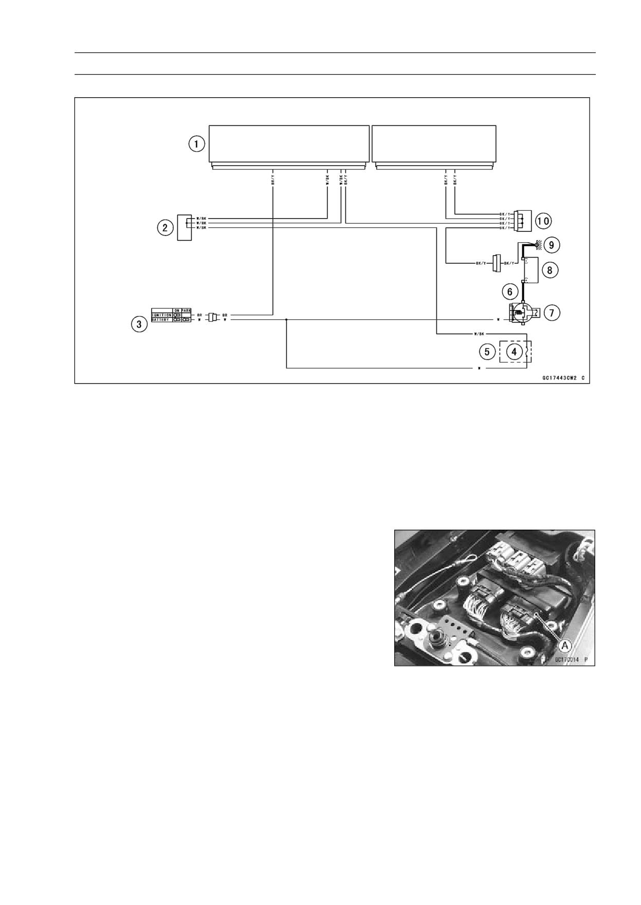
FUEL SYSTEM (DFI) 3-95
ECU
ECU Power Source Circuit
1. ECU
2. Water-proof Joint 1
3. Ignition Switch
4. ECU Fuse 15 A
5. Fuse Box 2
6. Starter Relay
7. Main Fuse 30 A
8. Battery 12 V 14 Ah
9. Frame Ground 2
10. Joint Connector 3
CAN Communication Line Resistance Inspection
○In this model, resistors for CAN communication line are
built in the ECU and meter unit.
• Turn the ignition switch OFF.
• Disconnect the ECU connector [A] (see ECU Removal).
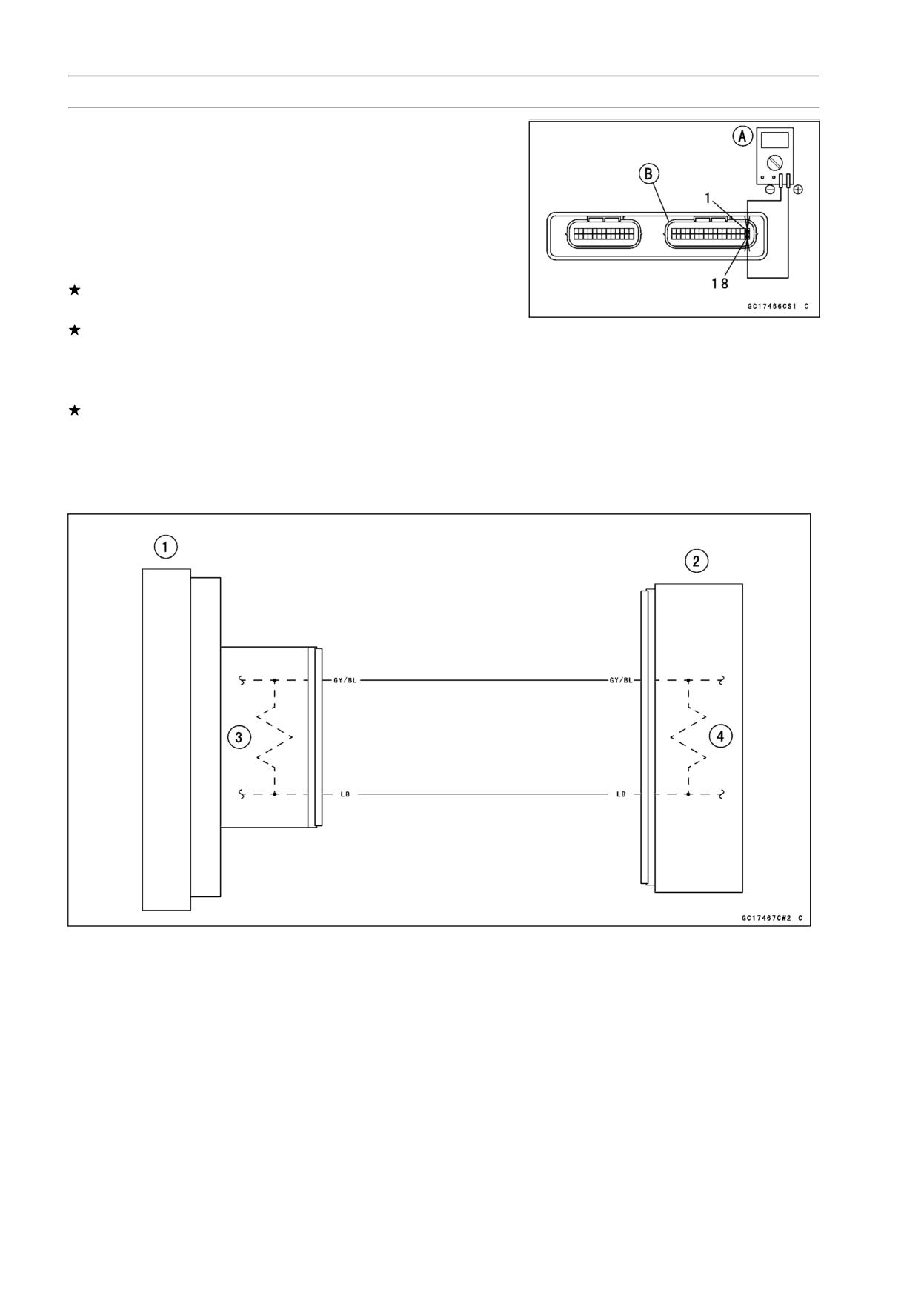
3-96 FUEL SYSTEM (DFI)
ECU
• Connect a digital meter [A] to the ECU connector [B].
• Measure the resistance of the CAN communication line
resistor.
CAN Communication Line Resistance (at ECU
Connector)
Connections: Terminal 1 ←→Terminal 18
Standard: 114 ∼ 126 Ω
If the reading is out of the range, replace the ECU (see
ECU section).
If the reading is within the range, resistor of the ECU for
CAN communication line is normal.
• Check the wiring for continuity of the CAN communication
line (see wiring diagram in this section).
If the wiring is open, replace the main harness.
• Refer to the Meter Unit Inspection in the Electrical System
chapter for the resistor in the meter unit (see Meter Unit
Inspection in the Electrical System chapter).
CAN Communication Line Circuit
1. Meter Unit
2. ECU
3. Resistor (In the Meter Unit)
4. Resistor (In the ECU)
FUEL SYSTEM (DFI) 3-97
DFI Power Source
ECU Fuse Removal
• Refer to the ECU Fuse 15 A Removal in the Electrical Sys-
tem chapter (see 15 A ECU Fuse Removal in the Electri-
cal System chapter).
ECU Fuse Installation
If a fuse fails during operation, inspect the DFI system to
determine the cause, and then replace it with a new fuse
of proper amperage.
• Refer to the Fuse installation in the Electrical System
chapter (see Fuse Installation in the Electrical System
chapter).
ECU Fuse Inspection
• Refer to the Fuse Inspection in the Electrical System
chapter (see Fuse Inspection in the Electrical System
chapter).
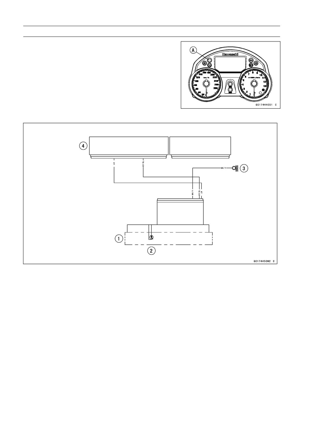
3-98 FUEL SYSTEM (DFI)
Warning Indicator Light (LED)
Light (LED) Inspection
○The warning indicator light (LED) [A] is used for the FI
indicator and immobilizer indicator (immobilizer models).
○In this model, the warning indicator light (LED) goes on or
blinks by the special signal sent from the ECU.
• Refer to the fuel level warning inspection procedure (see
Meter Unit Inspection in the Electrical System chapter) for
the warning indicator light (LED) inspection.
Warning Indicator Light (LED) Circuit
1. Meter Unit
2. Warning Indicator Light (LED)
3. Frame Ground 1
4. ECU
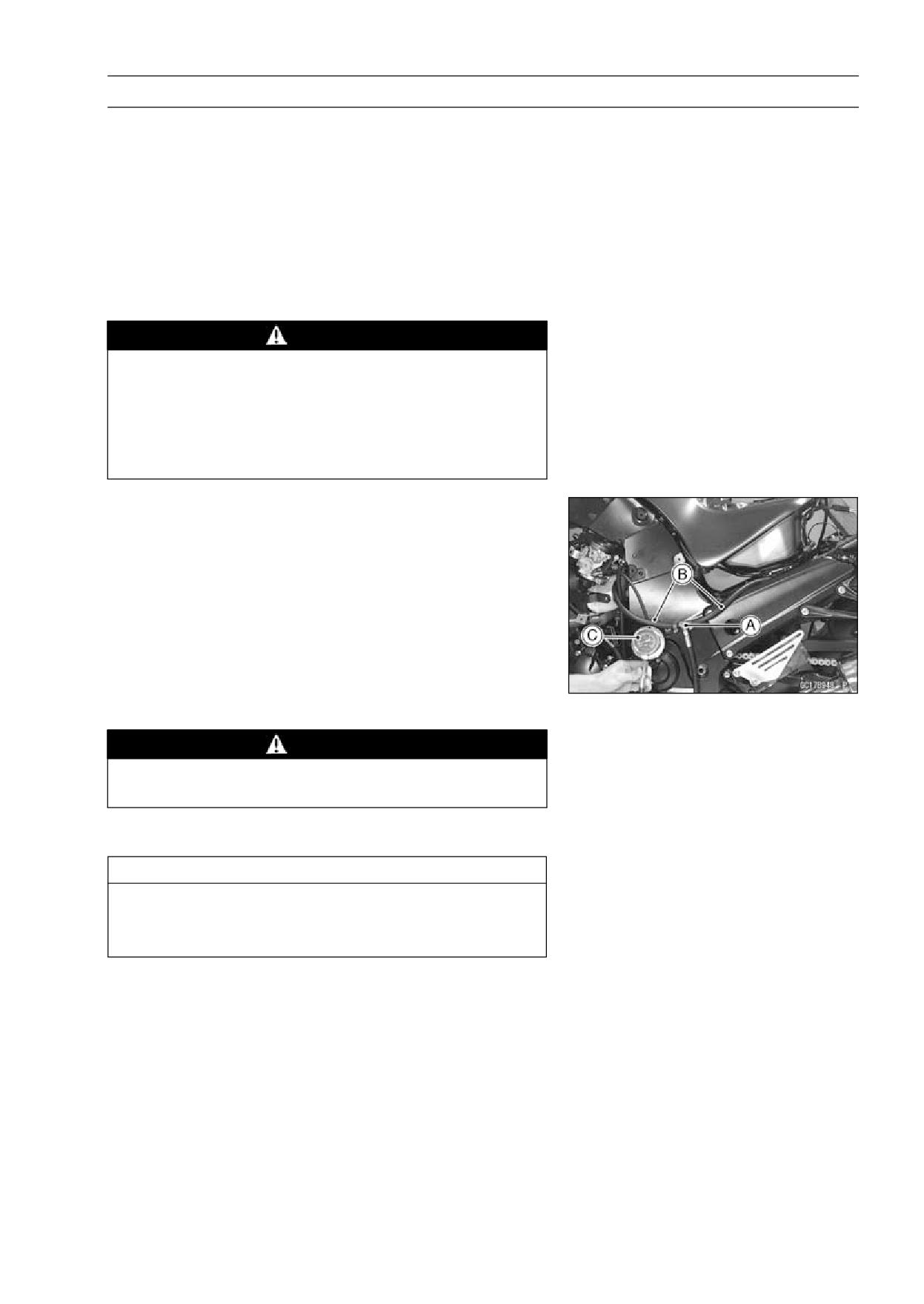
FUEL SYSTEM (DFI) 3-99
Fuel Line
Fuel Pressure Inspection
NOTE
○Be sure the battery is fully charged.
• Remove the fuel tank (see Fuel Tank Removal).
• Be sure to place a piece of cloth around the fuel supply
pipe of the throttle body assy.
• Remove the fuel hose from the fuel supply pipes of the
throttle body assy (see Fuel Hose Replacement in the
Periodic Maintenance chapter).
WARNING
Be prepared for fuel spillage; any spilled fuel must
be completely wiped up immediately.
When the fuel hose is disconnected, fuel spills out
from the hose and the pipe because of residual
pressure. Cover the hose connection with a piece
of clean cloth to prevent fuel spillage.
• Connect the following parts temporary.
Fuel Pump Lead Connector
Fuel Level Sensor Lead Connector
• Install the fuel pressure gauge adapter [A] and fuel hoses
(Special Tool: 57001-1607) [B] between the fuel supply
pipes of the fuel pump and throttle body assy.
• Connect the pressure gauge [C] to the fuel pressure
gauge adapter.
Special Tools - Oil Pressure Gauge, 5 kgf/cm²: 57001-125
Fuel Pressure Gauge Adapter: 57001-1593
Fuel Hose: 57001-1607
WARNING
Do not try to start the engine with the fuel hoses
disconnected.
• Turn the ignition switch ON. The fuel pump will turn for 3
seconds, and then stop.
CAUTION
Do not drive the fuel pump 3 seconds or more with-
out the fuel in the fuel tank. If the fuel pump is driven
without the fuel, it may be damaged.
• Measure the fuel pressure with the engine stopped.
Fuel Pressure
right after Ignition Switch ON, with pump running:
Standard: 304 kPa (3.1 kgf/cm², 44 psi)
after 3 seconds from Ignition Switch ON, with pump
stopped:
Standard:
280 kPa (2.9 kgf/cm², 41 psi) , residual fuel
pressure
The system should hold the residual
pressure about 30 seconds.
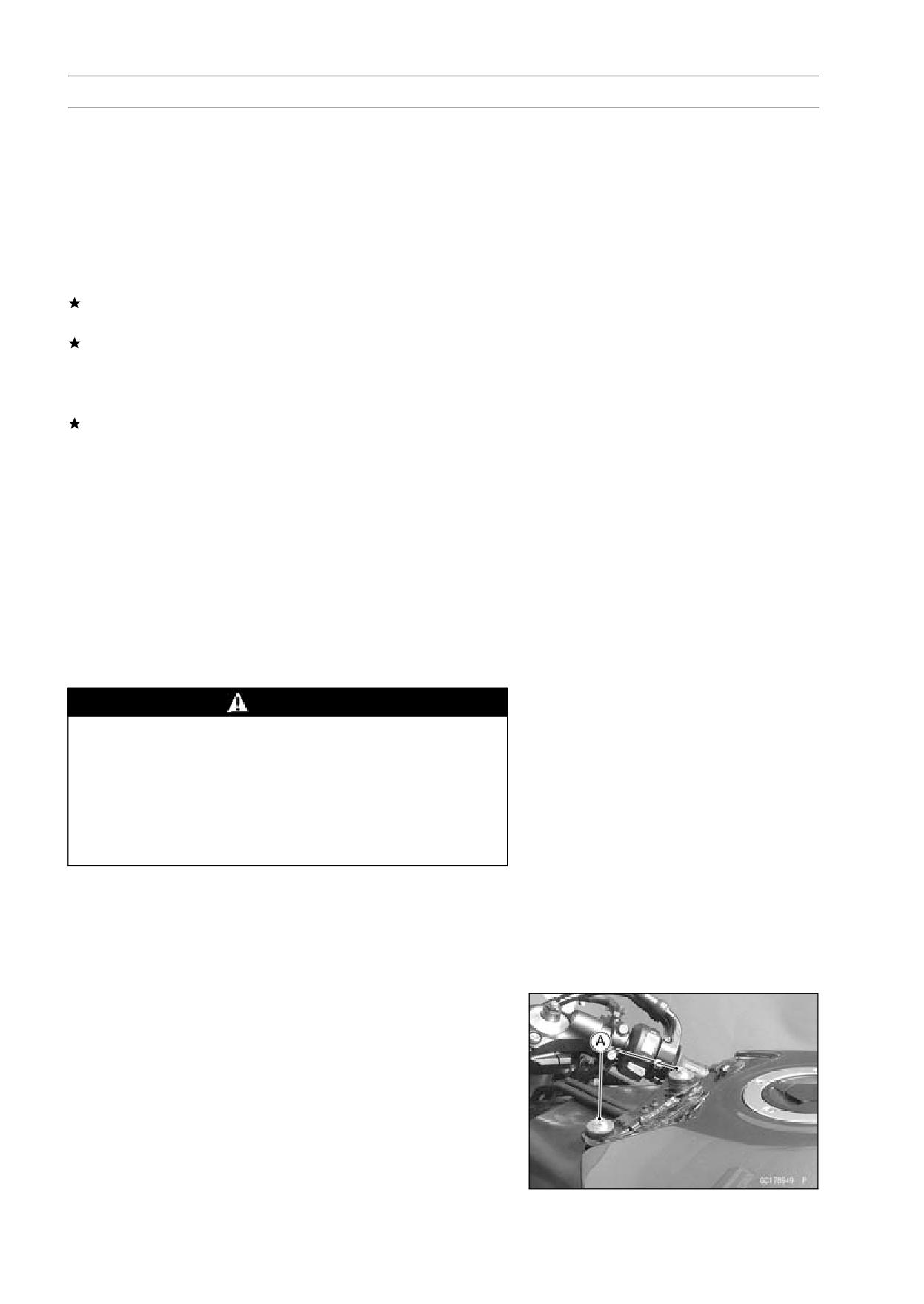
3-100 FUEL SYSTEM (DFI)
Fuel Line
• Start the engine, and let it idle.
• Measure the fuel pressure with the engine idling.
Fuel Pressure (idling)
Standard:
304 kPa (3.1 kgf/cm², 44 psi)
NOTE
○The gauge hand will fluctuate. Read the pressure at the
average of the maximum and minimum indications.
If the fuel pressure is much higher than the specified, re-
place the fuel pump (see Fuel Pump section).
If the fuel pressure is much lower than specified, check
the following.
Fuel Line Leakage
Amount of Fuel Flow (see Fuel Flow Rate Inspection)
If the fuel pressure is much lower than specified, and if
inspection above checks out good, replace the throttle
body assy, or the fuel pump and measure the fuel pres-
sure again (see appropriate sections).
• Remove the fuel pressure gauge, hoses and adapter.
• Install:
Fuel Hose (see Fuel Hose Replacement in the Periodic
Maintenance chapter)
Fuel Tank (see Fuel Tank Installation)
Fuel Flow Rate Inspection
NOTE
○Be sure the battery is fully charged.
WARNING
Gasoline is extremely flammable and can be explo-
sive under certain conditions. Make sure the area
is well-ventilated and free from any source of flame
or sparks; this includes any appliance with a pilot
light. Do not smoke. Turn the ignition switch OFF.
Be prepared for fuel spillage; any spilled fuel must
be completely wiped up immediately.
• Turn the ignition switch and engine stop switch OFF.
• Wait until the engine cools down.
57001-1607) and a
• Prepare a fuel hose (Special Tool:
measuring cylinder.
Special Tool - Fuel Hose: 57001-1607
• Remove:
Seat (see Seat Removal in the Frame chapter)
Fuel Tank Cover (see Fuel Tank Removal)
Fuel Tank Bolts [A]
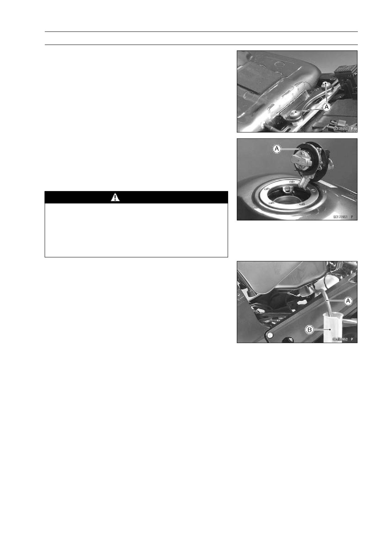
FUEL SYSTEM (DFI) 3-101
Fuel Line
• Remove the fuel tank bolts [A].
• Open the fuel tank cap [A] to lower the pressure in the
tank.
• Be sure to place a piece of cloth around the fuel supply
pipe of the fuel pump.
• Remove the fuel hose from the fuel pump (see Fuel Tank
Removal).
WARNING
Be prepared for fuel spillage; any spilled fuel must
be completely wiped up immediately.
When the fuel hose is disconnected, fuel spills out
from the hose and the pipe because of residual
pressure. Cover the hose connection with a piece
of clean cloth to prevent fuel spillage.
• Connect the prepared fuel hose [A] to the fuel supply pipe
of the fuel pump.
• Secure the fuel hose with a clamp.
• Insert the fuel hose into the measuring cylinder [B].
3-102 FUEL SYSTEM (DFI)
Fuel Line
WARNING
Wipe off spilled out fuel immediately.
Be sure to hold the measuring cylinder vertical.
• Close the fuel tank cap.
• With the engine stopped, turn the ignition switch ON. The
fuel pump should operate for 3 seconds, and then should
stop.
CAUTION
Do not drive the fuel pump 3 seconds or more with-
out the fuel in the fuel tank. If the fuel pump is driven
without the fuel, it may be damaged.
• Measure the discharge for 3 seconds.
○Repeat this operation several times.
Amount of Fuel Flow
Standard:
67 mL (2.26 US oz.) or more for 3 seconds
If the fuel flow is much less than the specified, check the
following.
Battery Condition (see Charging Condition Inspection in
the Electrical System chapter)
• After inspection, connect the fuel hose (see Fuel Tank
Installation).
• Start the engine and check for fuel leakage.
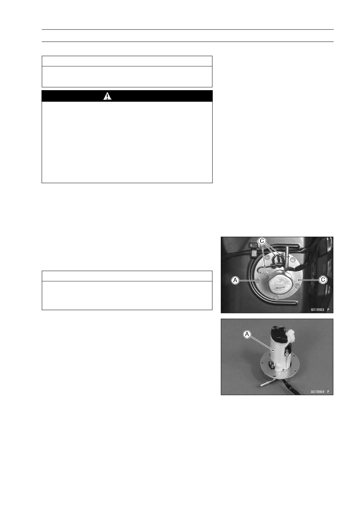
FUEL SYSTEM (DFI) 3-103
Fuel Pump
Fuel Pump Removal
CAUTION
Never drop the fuel pump, especially on a hard sur-
face. Such a shock to the pump can damage it.
WARNING
Gasoline is extremely flammable and can be explo-
sive under certain conditions. Make sure the area
is well-ventilated and free from any source of flame
or sparks; this includes any appliance with a pilot
light. Do not smoke. Turn the ignition switch OFF.
Disconnect the battery (-) terminal.
To make fuel spillage minimum, draw the fuel out
from the fuel tank when the engine is cold. Be
prepared for fuel spillage; any spilled fuel must be
completely wiped up immediately.
• Draw the fuel out from the fuel tank with a commercially
available electric pump.
• Remove the fuel tank (see Fuel Tank Removal).
○Be careful of fuel spillage from the fuel tank since fuel still
remains in the fuel tank and fuel pump. Plug the fuel pipe
of the fuel tank.
• Turn the fuel tank upside down.
• Unscrew the fuel pump bolts [A], and take out the fuel
pump assembly [B] and gasket.
• Discard the fuel pump gasket.
CAUTION
Do not pull the leads [C] of the fuel pump and fuel
reserve switch. If they are pulled, the lead terminals
may be damaged.
Fuel Pump Installation
• Remove dirt or dust from the fuel pump [A] by lightly ap-
plying compressed air.
• Replace the fuel pump gasket with a new one.
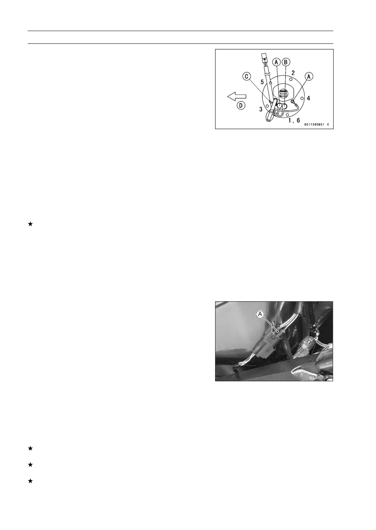
3-104 FUEL SYSTEM (DFI)
Fuel Pump
• Check that the fuel pump terminals [A], fuel reserve switch
terminal [B] and band [C] are in place.
Front [D]
• Apply a non-permanent locking agent to the threads of
the fuel pump bolts.
• Tighten the fuel pump bolts to a snug fit following the tight-
ening sequence shown.
• Following the tightening sequence, tighten the pump bolts
to the specified torque.
Torque - Fuel Pump Bolts: 9.8 N·m (1.0 kgf·m, 89 in·lb)
• Tighten the pump bolts again to check the tightness in the
order shown.
Operation Inspection
NOTE
○Be sure the battery is fully charged.
• Turn the ignition switch ON and make sure that the fuel
pump operates (make light sounds) for 3 seconds, and
then stops.
• Turn the ignition switch OFF.
If the pump does not work as described above, inspect
the operating voltage.
Operating Voltage Inspection
NOTE
○Be sure the battery is fully charged.
• Turn the ignition switch OFF.
• Remove the seat (see Seat Removal in the Frame chap-
ter).
• Connect the hand tester (× 25 V DC) to the 4 pins con-
nector [A], with needle adapter set.
Special Tools - Hand Tester: 57001-1394
Needle Adapter Set: 57001-1457
Pump Operating Voltage at Pump
Connections to Pump Connector
Tester (+) → BK/Y Lead
Tester (-) → BK/W Lead
• Measure the operating voltage with the engine stopped,
and with the connector joined.
• Turn the ignition switch ON.
○The tester needle should indicate battery voltage for 3
seconds, and then 0 V.
Operating Voltage at Pump Connector
Standard: Battery Voltage for 3 seconds, and then 0 V
If the reading stays on battery voltage, and never shows
0 V. Check the ECU and fuel pump relay.
If the voltage is in specification, but the pump doesn’t
work, replace the pump.
If there is still no battery voltage, check the pump relay
(see Fuel Pump Relay Inspection).
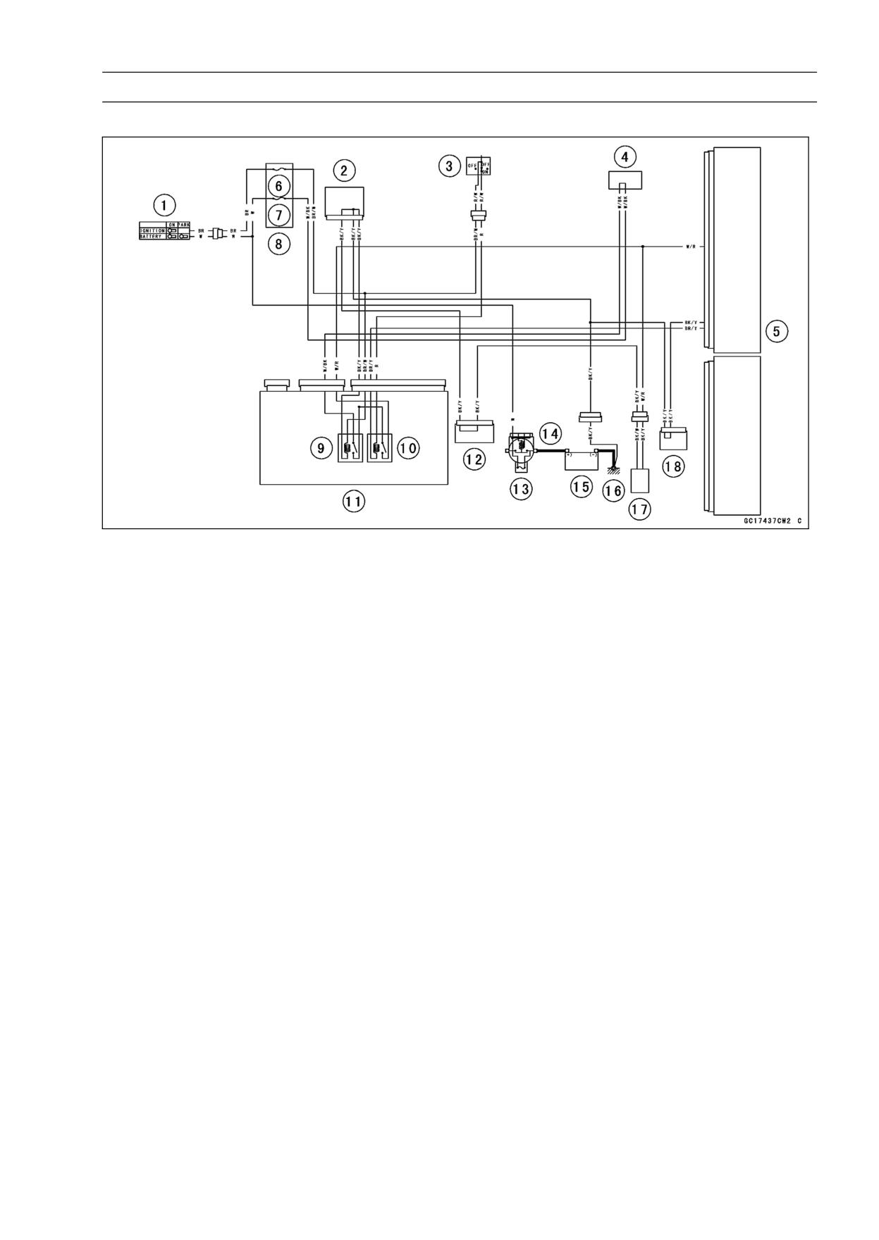
FUEL SYSTEM (DFI) 3-105
Fuel Pump
Fuel Pump Circuit
1. Ignition Switch
10. Fuel Pump Relay
2. Joint Connector 1
11. Relay Box
3. Engine Stop Switch
12. Joint Connector 2
4. Water-proof Joint 1
13. Main Fuse 30 A
5. ECU
14. Starter Relay
6. ECU Fuse 15 A
15. Battery 12 V 14 Ah
7. Ignition Fuse 10 A
16. Frame Ground 2
8. Fuse Box 2
17. Fuel Pump
9. Main Relay
18. Joint Connector 3
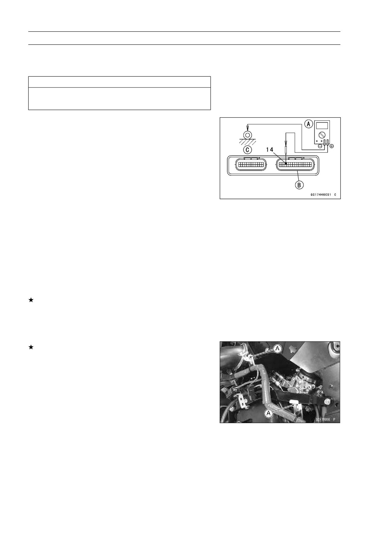
3-106 FUEL SYSTEM (DFI)
Fuel Injectors
Removal/Installation
• Refer to the Throttle Body Assy Disassembly/Assembly
(see Throttle Body Assy Disassembly/Assembly).
CAUTION
Never drop the injector, especially on a hard sur-
face. Such a shock to the injector can damage it.
Power Source Voltage Inspection
NOTE
○Be sure the battery is fully charged.
• Turn the ignition switch OFF.
• Remove the ECU (see ECU Removal).
○Do not disconnect the ECU connectors.
• Connect a digital meter [A] to the connector [B], with the
needle adapter set.
Special Tool - Needle Adapter Set: 57001-1457
Injector Power Source Voltage at ECU Connector
Connections to ECU Connector
Meter (+) → W/R lead (terminal 14)
Meter (-) → Frame Ground 2 [C]
• Measure the power source voltage with the engine
stopped, and with the connectors joined.
• Turn the ignition switch ON.
Power Source Voltage at ECU
Standard: Battery Voltage for 3 seconds, and then 0 V
If the power source voltage is less than the standard,
check the fuel pump relay (see Fuel Pump Relay Inspec-
tion), wiring (see wiring diagram in this section), and the
ECU for its ground, and power supply (see ECU Power
Supply Inspection chapter).
If the reading is normal, check the power source voltage
at the injector connector.
• Remove:
Left Middle Fairing (see Middle Fairing Removal in the
Frame chapter)
Bolts [A]
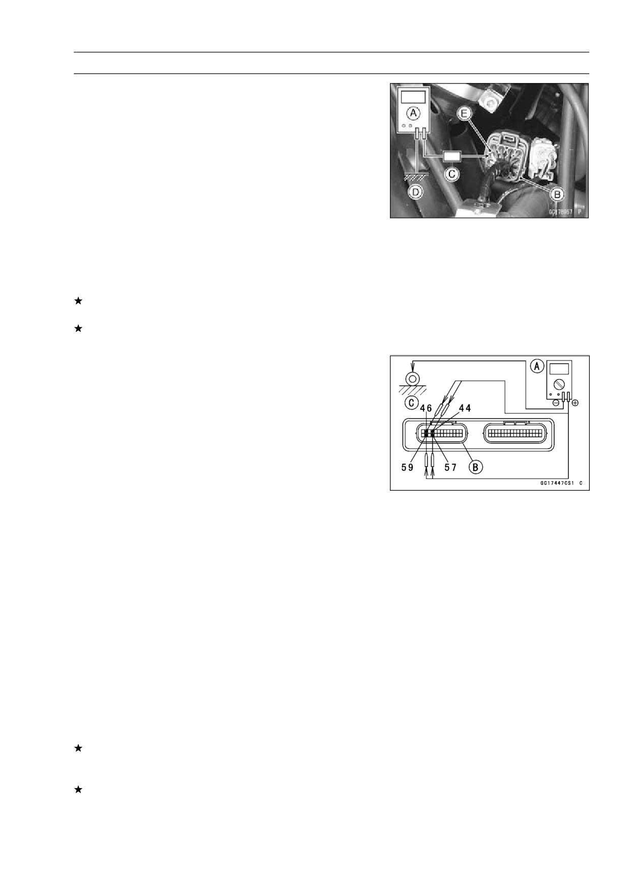
FUEL SYSTEM (DFI) 3-107
Fuel Injectors
• Connect a digital meter [A] to the throttle body subharness
connector [B], using the needle adapter set [C].
Special Tool - Needle Adapter Set: 57001-1457
Injector Power Source Voltage at Injector
Connections to Injector #1, #2, #3, #4
Meter (+) → W/R lead [E]
Meter (-) → Ground [D]
• Measure the power source voltage with the engine
stopped, and with the connector joined.
• Turn the ignition switch ON.
Power Source Voltage at Injector Connector
Standard: Battery Voltage for 3 seconds, and then 0 V
• Turn the ignition switch OFF.
If the reading is out of the standard, check the wiring (see
wiring diagram in this section).
If the reading is good, and the power source voltage is
normal, check the output voltage.
Output Voltage Inspection
• Measure the output voltage at the ECU connector in the
same way as power source voltage inspection. Note the
following.
Digital Meter [A]
Connector [B]
Special Tool - Needle Adapter Set: 57001-1457
Injector Output Voltage at ECU
Connections for Injector #1
Meter (+) → BL/R lead (terminal 46)
Meter (-) → Frame Ground 2 [C]
Connections for Injector #2
Meter (+) → BL/G lead (terminal 59)
Meter (-) → Frame Ground 2 [C]
Connections for Injector #3
Meter (+) → BL/BK lead (terminal 44)
Meter (-) → Frame Ground 2 [C]
Connections for Injector #4
Meter (+) → BL/Y lead (terminal 57)
Meter (-) → Frame Ground 2 [C]
• Turn the ignition switch ON.
Output Voltage at ECU
Standard: Battery Voltage for 3 seconds, and then 0 V
If the output voltage is normal, check the ECU for its
ground, and power supply (see ECU Power Supply In-
spection).
If the ground and power supply are good, replace the ECU
(see ECU section).
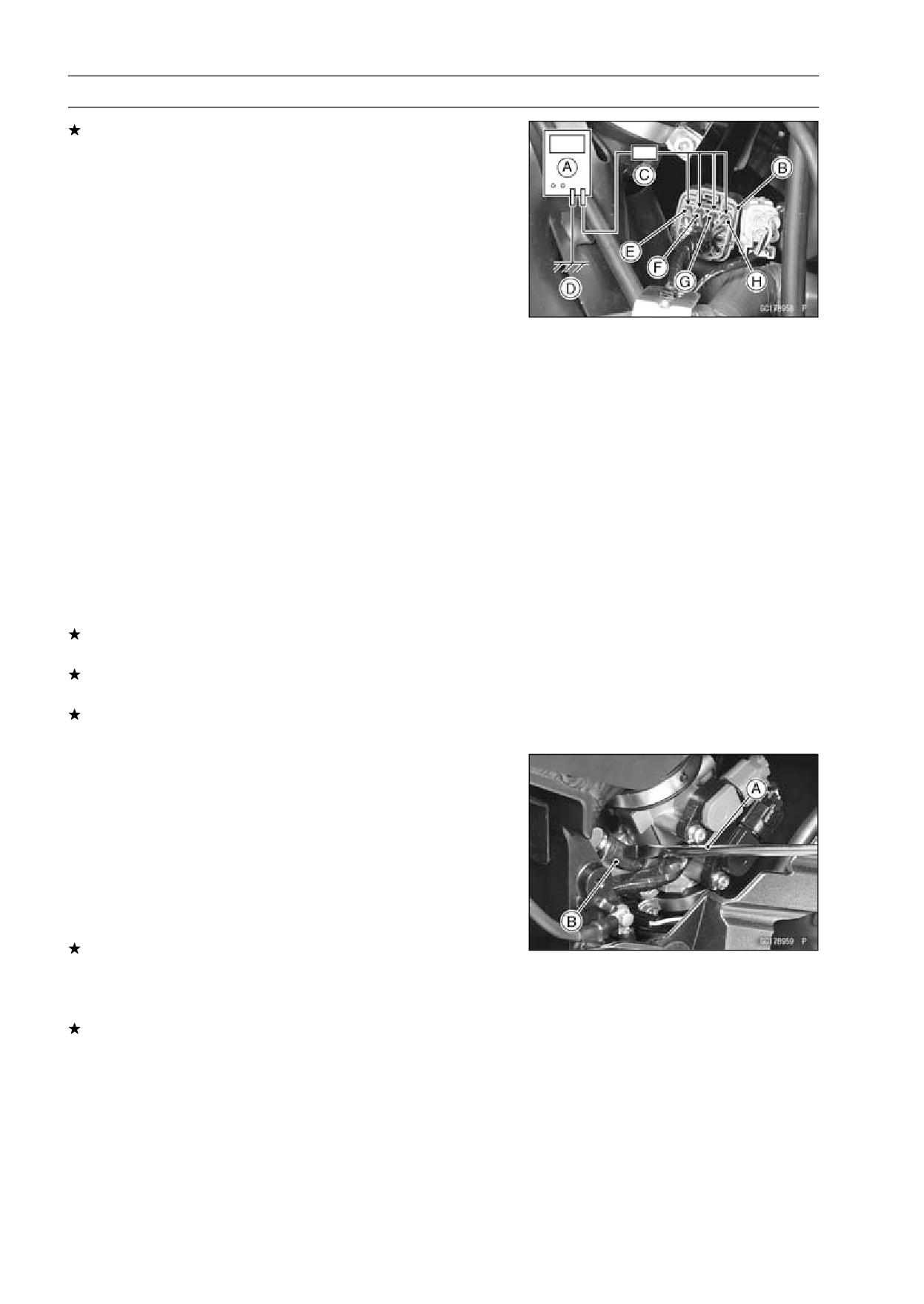
3-108 FUEL SYSTEM (DFI)
Fuel Injectors
If the output voltage is out of the standard, check the out-
put voltage at the throttle body subharness connector [B]
using a digital meter [A] and needle adapter set [C] (when
the lead is open, the output voltage is 0 V).
Special Tool - Needle Adapter Set: 57001-1457
Injector Output Voltage at Injector
Connections to Injector #1
Meter (+) → BL/R lead [E]
Meter (-) → Ground [D]
Connections to Injector #2
Meter (+) → BL/G lead [F]
Meter (-) → Ground [D]
Connections to Injector #3
Meter (+) → BL/BK lead [G]
Meter (-) → Ground [D]
Connections to Injector #4
Meter (+) → BL/Y lead [H]
Meter (-) → Ground [D]
• Turn the ignition switch ON.
Output Voltage at Injector Connector
Standard: Battery Voltage for 3 seconds, and then 0 V
If the output voltage is normal, check the wiring for conti-
nuity (see wiring diagram in this section).
If the wiring is good, perform “Audible Inspection” for con-
firmation.
If the output voltage is out of the standard, perform “Au-
dible Inspection” for confirmation.
Audible Inspection
• Remove the left and right fairing cover (see Fairing Cover
Removal in the Frame chapter).
• Start the engine.
• Apply the tip of a screwdriver [A] to the injector [B]. Put
the grip end onto your ear, and listen whether the injector
is clicking or not.
•A sound scope can also be used.
• Do the same for the other injector.
If all the injectors click at a regular intervals, the injectors
are good.
○The click interval becomes shorter as the engine speed
rises.
If either injector doesn’t click, perform the “Injector Signal
Test” for injector operation.
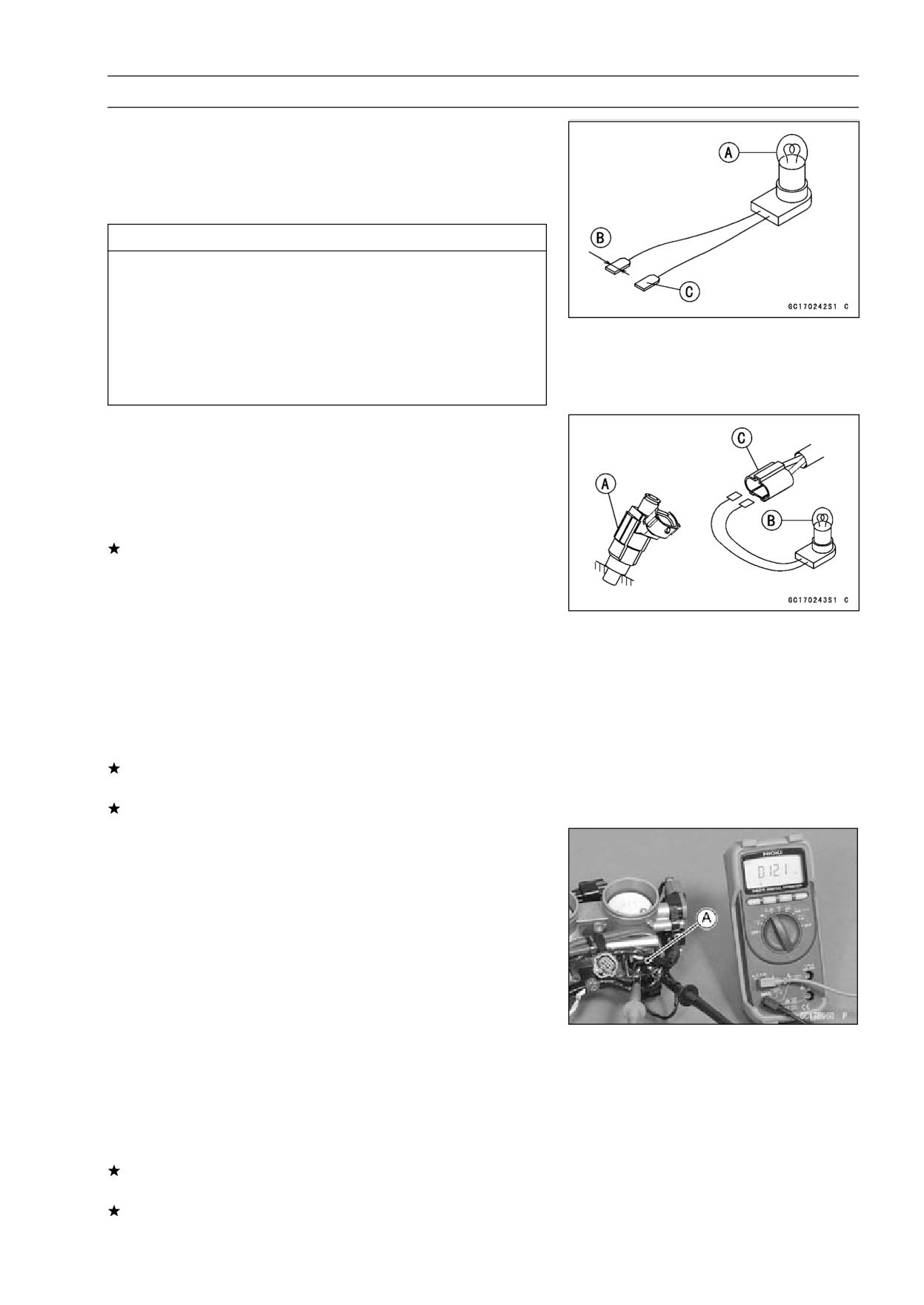
FUEL SYSTEM (DFI) 3-109
Fuel Injectors
Injector Signal Test
• Prepare two test light sets with male terminals as shown.
Rating of Bulb [A]: 12 V × 3 ~ 3.4 W
Terminal Width [B]: 1.8 mm (0.07 in.)
Terminal Thickness [C]: 0.8 mm (0.03 in.)
CAUTION
Do not use larger terminals than specified above. A
larger terminal could damage the injector main har-
ness connector (female), leading to harness repair
or replacement.
Be sure to connect bulbs in series. The bulb works
as a current limiter to protect the solenoid in the
injector from excessive current.
• Disconnect the connectors for injector [A].
• Connect each test light set [B] to the injector sub harness
connector [C].
• Turn the ignition switch ON.
• While cranking the engine with the starter motor, watch
the test lights.
If the test lights flicker at regular intervals, the injector
circuit in the ECU, and the wiring are good. Perform the
“Injector Resistance Inspection”.
○Injector signals can be also confirmed by connecting the
hand tester (× 10 V AC) instead of the test light set to
the injector main harness (female) connector. Crank the
engine with the starter motor, and check to see if the hand
oscillates at regular intervals.
Special Tool - Hand Tester: 57001-1394
If the test light does not flicker (or the test hand doesn’t
oscillates), check the wiring and connectors again.
If the wiring is good, replace the ECU (see ECU section).
Injector Resistance Inspection
• Remove the throttle body assy (see Throttle Body Assy
Removal).
• Disconnect the connector from the injector [A] (see Throt-
tle Body Disassembly/Assembly).
• Measure the injector resistance with a digital meter.
Injector Resistance
Connections to Injector
Meter (+)
Meter (-)
#1: W/R
←→
BL/R Terminal
#2: W/R
←→
BL/G Terminal
#3: W/R
←→
BL/BK Terminal
#4: W/R
←→
BL/Y Terminal
Standard: about 11.7 ∼ 12.3 Ω at 20°C (68°F)
If the reading is out of the range, perform the “Injector Unit
Test”.
If the reading is normal, perform the “Injector Unit Test”
for confirmation.
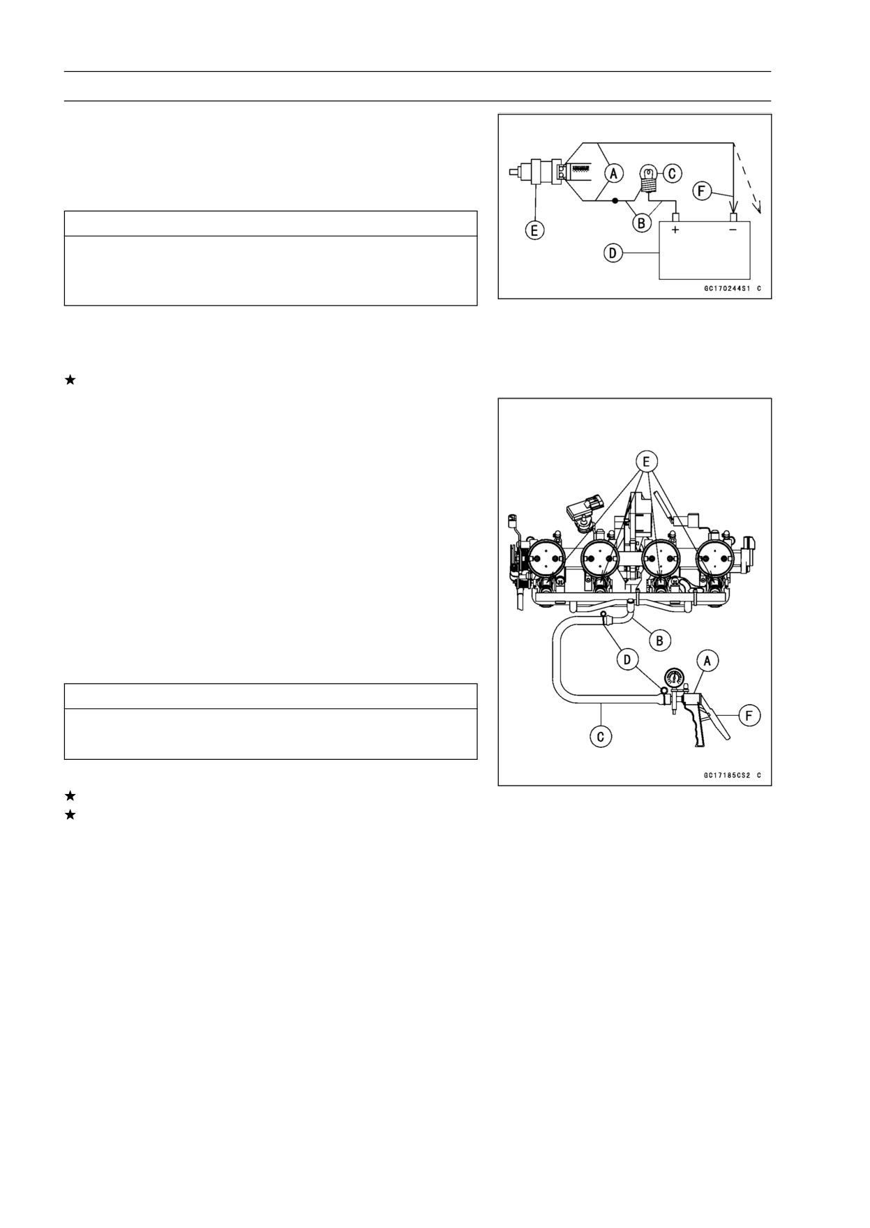
3-110 FUEL SYSTEM (DFI)
Fuel Injectors
Injector Unit Test
• Use two leads [A] and the same test light set [B] as in
“Injector Signal Test”.
Rating of Bulb [C]: 12 V × (3 ∼ 3.4) W
12 V MF Battery [D]
CAUTION
Be sure to connect the bulb in series. The bulb
works as a current limiter to protect the solenoid
in the injector from excessive current.
• Connect the test light set to the injector [E] as shown.
• Open and connect [F] the end of the lead to the battery
(-) terminal repeatedly. The injector should click.
If the injector does not click, replace the injector.
Injector Fuel Line Inspection
• Remove the throttle body assy (see Throttle Body Assy
Removal).
• Check the injector fuel line for leakage as follows.
○Connect a commercially available vacuum/pressure
pump [A] to the nipple of the delivery pipe [B] with the
fuel hose [C] (both ends connected with the clamps [D])
as shown.
○Apply soap and water solution to the areas [E] as shown.
○Watching the pressure gauge, squeeze the pump lever
[F], and build up the pressure until the pressure reaches
the maximum pressure.
Fuel Line Maximum Pressure
Standard:
300 kPa (3.06 kgf/cm², 43 psi)
CAUTION
During pressure testing, do not exceed the maxi-
mum pressure for which the system is designed.
• Watch the gauge for at least 6 seconds.
If the pressure holds steady, the system is good.
If the pressure drops at once, or if bubbles are found in
the area, the line is leaking. Replace the delivery pipe,
injectors and related parts.
○Repeat the leak test, and check the fuel line for no leak-
age.
• Install the throttle body assy (see Throttle Body Assy In-
stallation).
• Run the hoses correctly (see Cable, Wire, and Hose Rout-
ing section in the Appendix chapter).
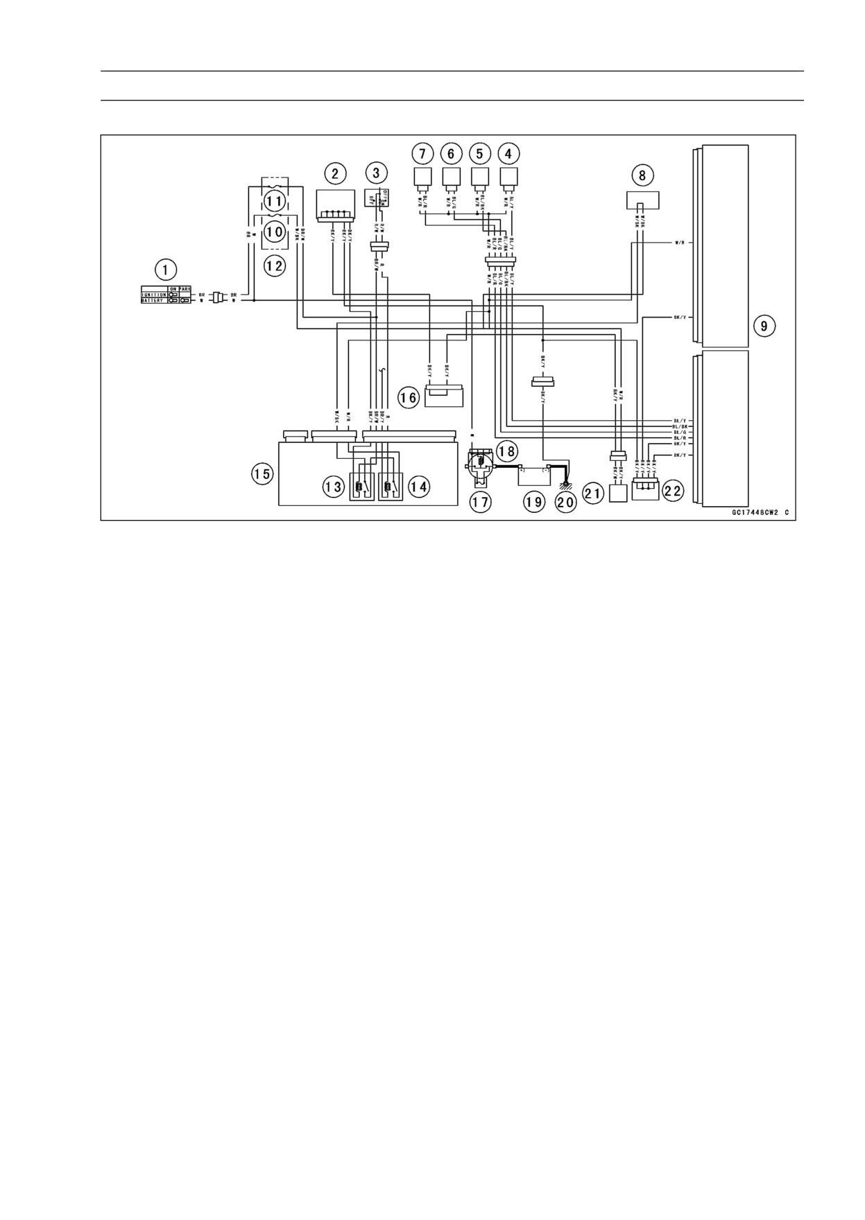
FUEL SYSTEM (DFI) 3-111
Fuel Injectors
Fuel Injector Circuit
1. Ignition Switch
12. Fuse Box 2
2. Joint Connector 1
13. Main Relay
3. Engine Stop Switch
14. Fuel Pump Relay
4. Fuel Injector #4
15. Relay Box
5. Fuel Injector #3
16. Joint Connector 2
6. Fuel Injector #2
17. Main Fuse 30 A
7. Fuel Injector #1
18. Starter Relay
8. Water-proof Joint 1
19. Battery 12 V 14 Ah
9. ECU
20. Frame Ground 2
10. ECU Fuse 15 A
21. Fuel Pump
11. Ignition Fuse 10 A
22. Joint Connector 3
3-112 FUEL SYSTEM (DFI)
Throttle Grip and Cables
Free Play Inspection
• Refer to the Throttle Control System Inspection in the Pe-
riodic Maintenance chapter (see Throttle Control System
Inspection in the Periodic Maintenance chapter).
Free Play Adjustment
• Refer to the Throttle Control System Inspection in the Pe-
riodic Maintenance chapter (see Throttle Control System
Inspection in the Periodic Maintenance chapter).
Cable Installation
• Install the throttle cables in accordance with the Cable ,
Wire, and Hose Routing section in the Appendix chapter.
• Install the lower ends of the throttle cables in the cable
bracket on the throttle assy after installing the upper ends
of the throttle cables in the grip.
• After installation, adjust each cable properly (see Throttle
Control System Inspection in the Periodic Maintenance
chapter).
WARNING
Operation with incorrectly routed or improperly ad-
justed cables could result in an unsafe riding con-
dition.
Cable Lubrication
• Refer to the Chassis Parts Lubrication Perform in the Peri-
odic Maintenance chapter (see Chassis Parts Lubrication
Perform in the Periodic Maintenance chapter).
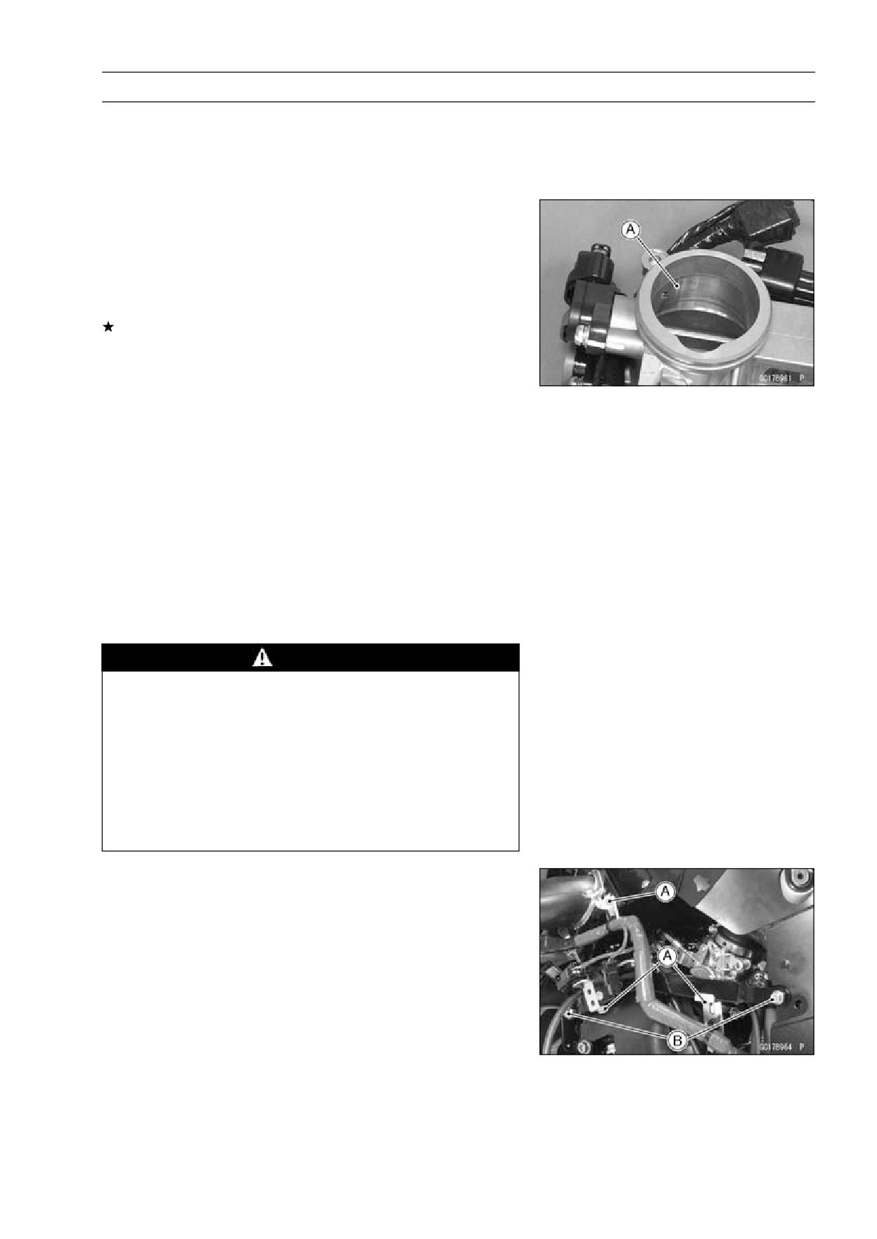
FUEL SYSTEM (DFI) 3-113
Throttle Body Assy
Idle Speed Inspection
• Refer to the Idle Speed Inspection in the Periodic Mainte-
nance chapter (see Idle Speed Inspection in the Periodic
Maintenance chapter).
Throttle Bore Cleaning
• Check the throttle bore for cleanliness as follows.
○Remove the throttle body assy (see Throttle Body Assy
Removal).
○Check the main throttle valves and throttle bores [A] for
carbon deposits by opening the main throttle valves.
If any carbon accumulates, wipe the carbon off the throt-
tle bores around the throttle bores and the throttle valves,
using a cotton pad penetrated with a high-flash point sol-
vent.
Synchronization Inspection
• Refer to the Engine Vacuum Synchronization Inspection
in the Periodic Maintenance chapter (see Engine Vacuum
Synchronization Inspection in the Periodic Maintenance
chapter).
Synchronization Adjustment
• Refer to the Engine Vacuum Synchronization Inspection
in the Periodic Maintenance chapter (see Engine Vacuum
Synchronization Inspection in the Periodic Maintenance
chapter).
Throttle Body Assy Removal
WARNING
Gasoline is extremely flammable and can be ex-
plosive under certain conditions. Turn the ignition
switch OFF. Disconnect the battery (-) cable ter-
minal. Do not smoke. Make sure the area is
well-ventilated and free from any source of flame
or sparks; this includes any appliance with a pilot
light.
Be prepared for fuel spillage: any spilled fuel must
be completely wiped up immediately.
• Remove:
Fuel Tank Cover (see Fuel Tank Removal)
Left and Right Middle Fairings (see Middle Fairing Re-
moval in the Frame chapter)
Bolts [A]
Subframe Bolts [B] and Washers
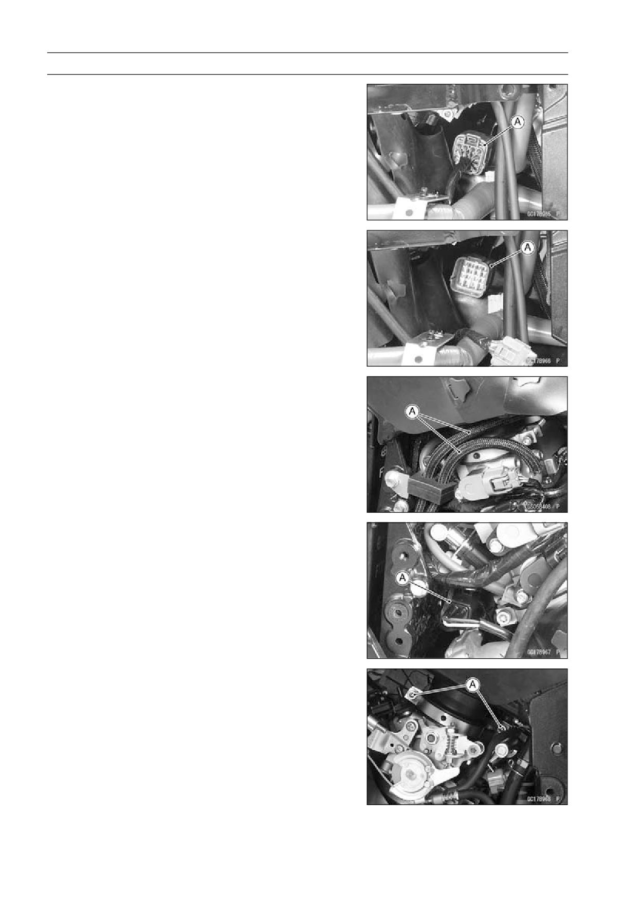
3-114 FUEL SYSTEM (DFI)
Throttle Body Assy
• Disconnect the throttle body subharness connector [A].
• Remove the connector [A] from the connector bracket.
○Insert the thin blade screw driver into the connector stop-
per portion from the right side of motorcycle.
• For the California Model, pull off the vacuum hoses [A].
• Disconnect the crankshaft sensor lead connector [A].
• Loosen the duct clamp bolts [A] on both sides.
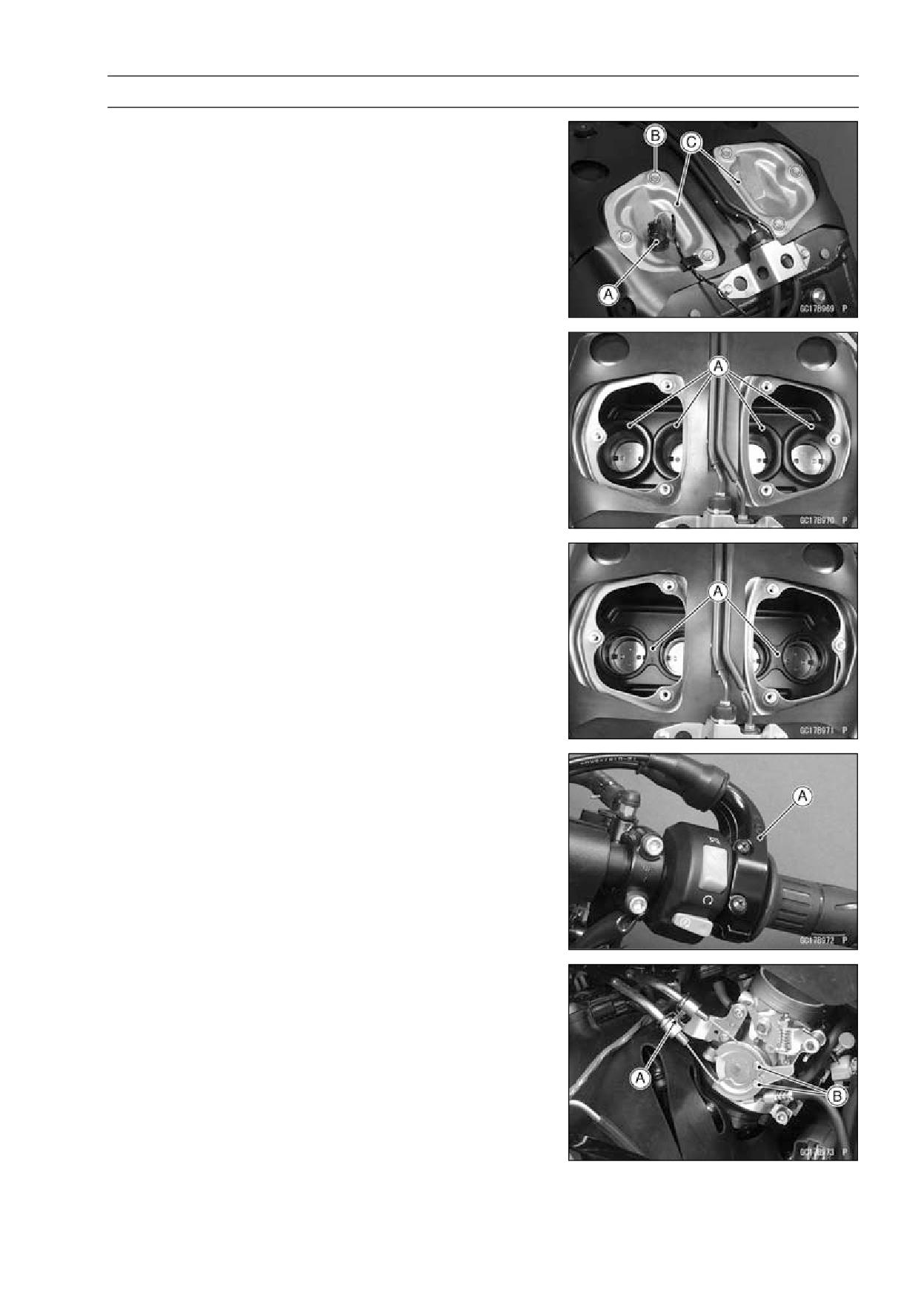
FUEL SYSTEM (DFI) 3-115
Throttle Body Assy
• Remove:
Fuel Tank (see Fuel Tank Removal)
Inlet Air Temperature Sensor [A]
Bolts [B]
Left and Right Air Cleaner Caps [C]
○Do not disconnect the inlet air temperature sensor lead
connector.
• Remove the duct clamps from the ducts [A], and pull out
the ducts upward.
○Remove the grommets [A] as necessary.
• Remove the throttle case [A] to make a throttle cable
slack.
• Remove:
Clamp [A]
Throttle Cable Lower Ends [B]
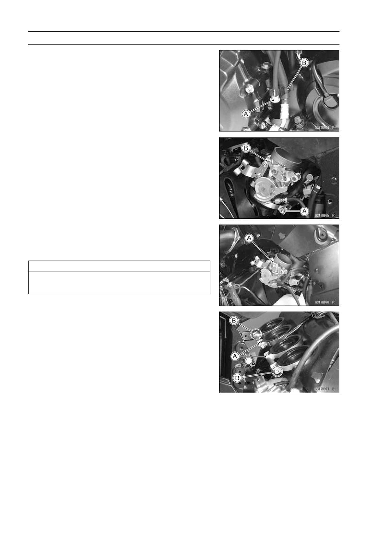
3-116 FUEL SYSTEM (DFI)
Throttle Body Assy
• Remove the adjuster screw [A] from the clamp [B].
• Loosen the throttle body assy holder clamp bolts [A] on
both sides.
• Pull out the throttle body assy [B] from the holder.
• Disconnect the fuel hose joint from the delivery pipe of
the throttle body assy (see Fuel Hose Replacement in the
Periodic Maintenance chapter).
• Remove the throttle body assy [A] to the left side of mo-
torcycle.
• After removing the throttle body assy, stuff pieces of lint
-free, clean cloths into the throttle body assy holders.
CAUTION
If dirt gets into the engine, excessive engine wear
and possible engine damage will occur.
Throttle Body Assy Installation
• Install the holder clamp bolts [A] in the direction as shown.
Bolt Heads [B]
• Connect the fuel hose joint to the delivery pipe of the throt-
tle body assy (see Fuel Hose Replacement in the Periodic
Maintenance chapter).
• Tighten:
Torque - Throttle Body Assy Holder Clamp Bolts: 2.0 N·m
(0.20 kgf·m, 18 in·lb)
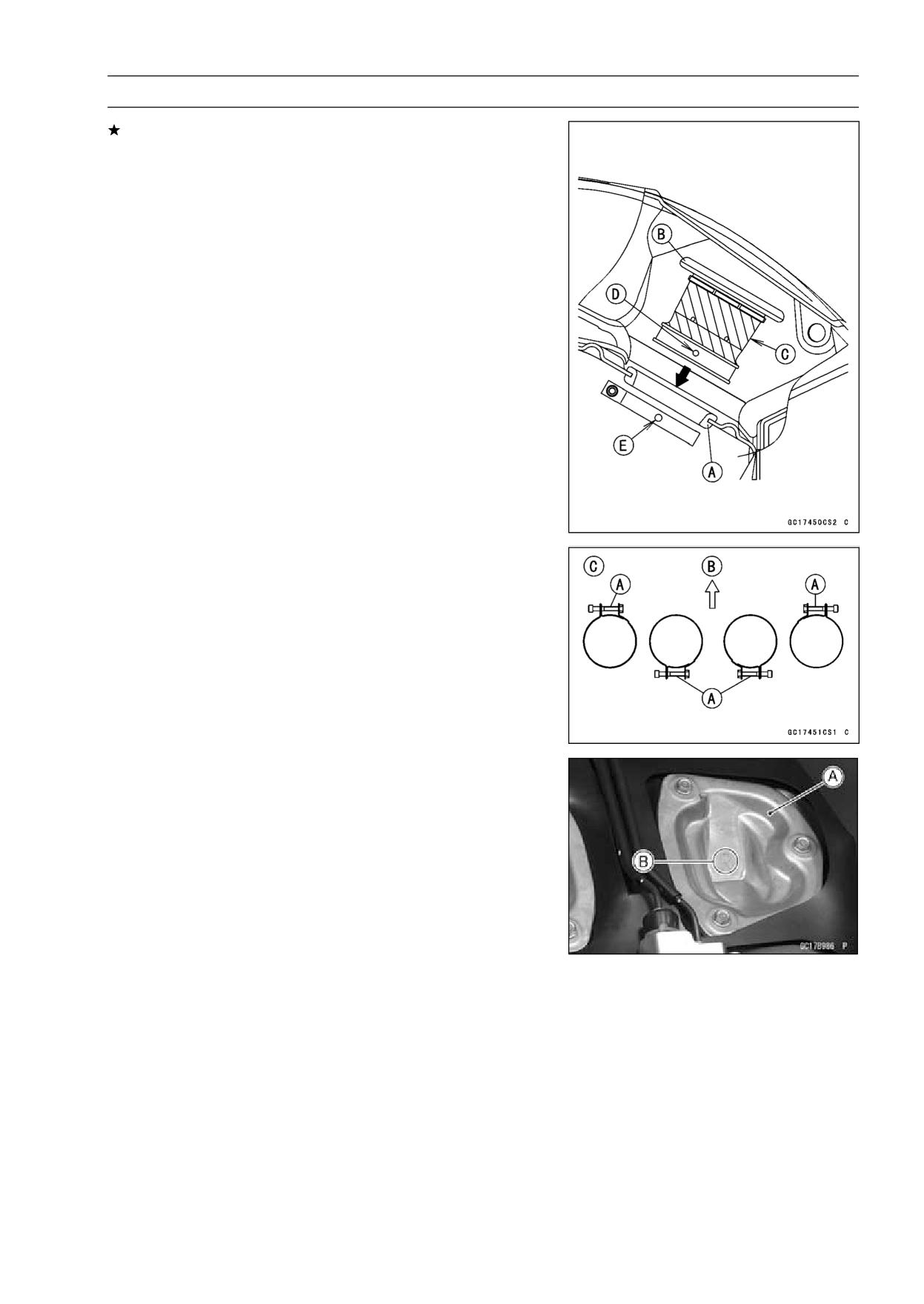
FUEL SYSTEM (DFI) 3-117
Throttle Body Assy
If the grommet [A] was removed, install it.
○Install the grommet from the inside of the frame.
• Insert the duct [B] to the grommet.
○Apply a soap and water solution or rubber lubricant to the
oblique portion [C] on the duct for easy installation.
• Fit the projections [D] of the duct into the holes [E] in the
clamp.
• Install the duct clamp bolts [A] in the direction as shown.
Front [B]
Upside View [C]
• Tighten:
Torque - Duct Clamp Bolts: 2.0 N·m (0.20 kgf·m, 18 in·lb)
• Install the air cleaner caps.
○The right air cleaner cap [A] has a R mark [B].
• Replace the subframe bolts with new ones, and tighten it.
Torque - Subframe Bolts: 23 N·m (2.3 kgf·m, 17 ft·lb)
• Run the leads and hoses as shown in the Cable, Wire,
and Hose Routing section of the Appendix chapter.
• Adjust:
Throttle Grip Free Play (see Throttle Control System In-
spection in the Periodic Maintenance chapter)
Idle Speed (see Idle Speed Adjustment in the Periodic
Maintenance chapter)
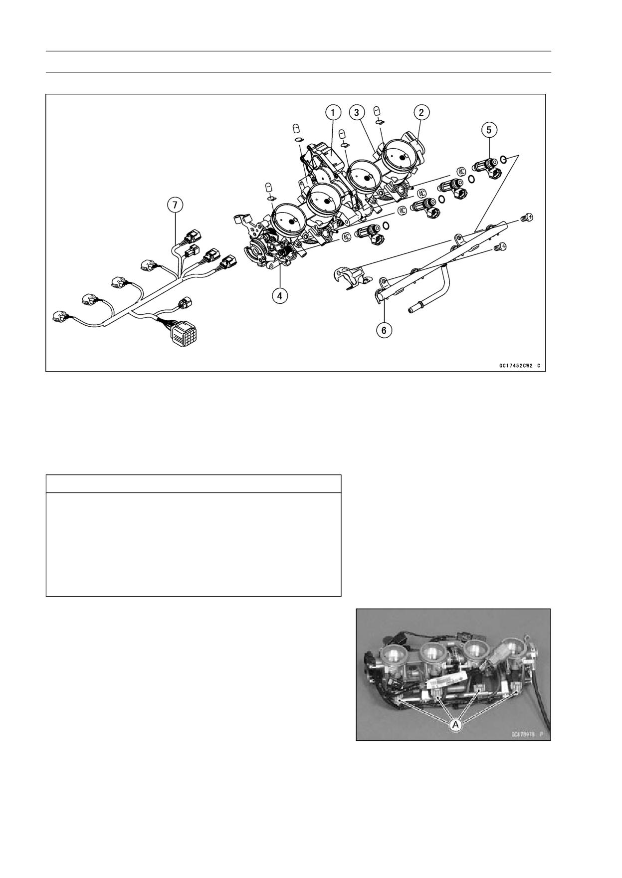
3-118 FUEL SYSTEM (DFI)
Throttle Body Assy
Throttle Body Assy Disassembly
1. Subthrottle Valve Actuator
2. Subthrottle Sensor
3. Main Throttle Sensor
4. Throttle Body Assy
5. Injector
6. Delivery Pipe
7. Throttle Body Subharness
CAUTION
Do not remove, disassemble or adjust the main
throttle sensor, subthrottle sensor, subthrottle
valve actuator, throttle link mechanism and throttle
body assy, because they are adjust or set surely at
the manufacturer. Adjustment of these parts could
result in poor performance, requiring replacement
of the throttle body assy.
• Remove the throttle body assy (see Throttle Body Assy
Removal).
• Disconnect the injector connectors [A].
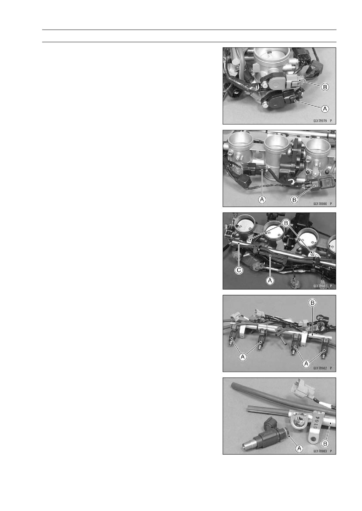
FUEL SYSTEM (DFI) 3-119
Throttle Body Assy
• Disconnect the main throttle sensor [A] and subthrottle
sensor [B] connector.
• Disconnect:
Subthrottle Valve Actuator Lead Connector [A]
Inlet Air Pressure Sensor Connector [B]
• Separete the hoses [A] from the throttle body fittings and
inlet air pressure sensor.
• Remove the screws [B] to pull out the injector assies from
the throttle body assy together with the delivery pipe [C].
NOTE
○Do not damage the insertion portions of the injectors
when they are pulled out from the throttle body.
• Pull out the injectors [A] from the delivery pipe [B].
NOTE
○Do not damage the insertion portions of the injectors
when they are pulled out from the delivery pipe.
Throttle Body Assy Assembly
• Before assembling, blow away dirt or dust from the throttle
body and delivery pipe by applying compressed air.
• Apply daphne oil or engine oil to the new O-rings [A] of
each injector, insert them to the delivery pipe [B] and con-
firm whether the injectors turn smoothly or not.
NOTE
○Replace the O-rings of injectors to new ones.
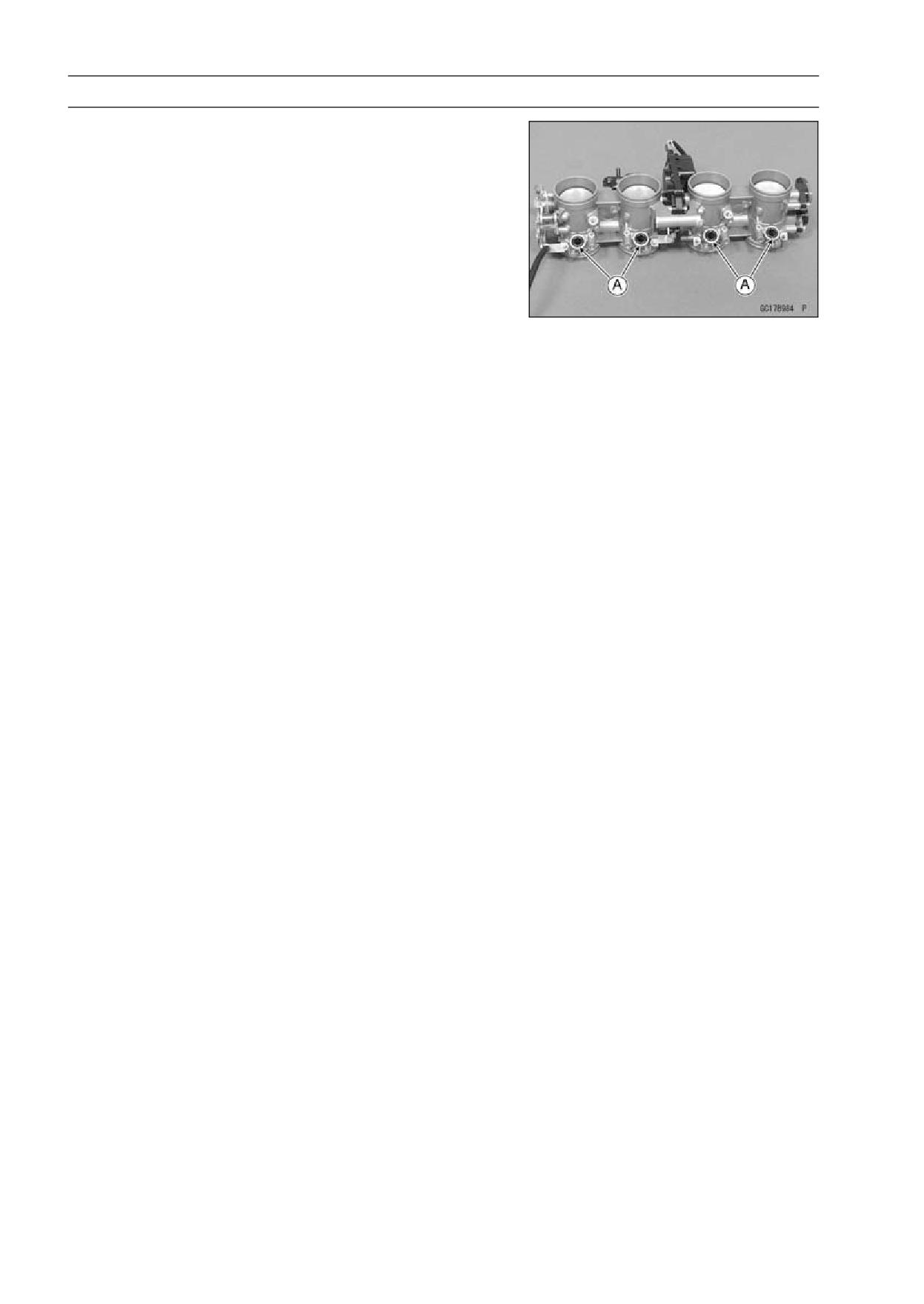
3-120 FUEL SYSTEM (DFI)
Throttle Body Assy
• Apply daphne oil or engine oil to the new dust seals [A],
and insert the injectors into the throttle body, which in-
stalled to the delivery pipe.
NOTE
○Replace the dust seals of the throttle body to new ones.
• Install the delivery pipe to the throttle body.
Torque - Delivery Pipe Mounting Screws:
5.0 N·m (0.50
kgf·m, 44 in·lb)
• Connect the injector connectors.
• Insert the each hoses to the throttle body fittings and inlet
air pressure sensor.
• Install the throttle body assy (see Throttle Body Assy In-
stallation).
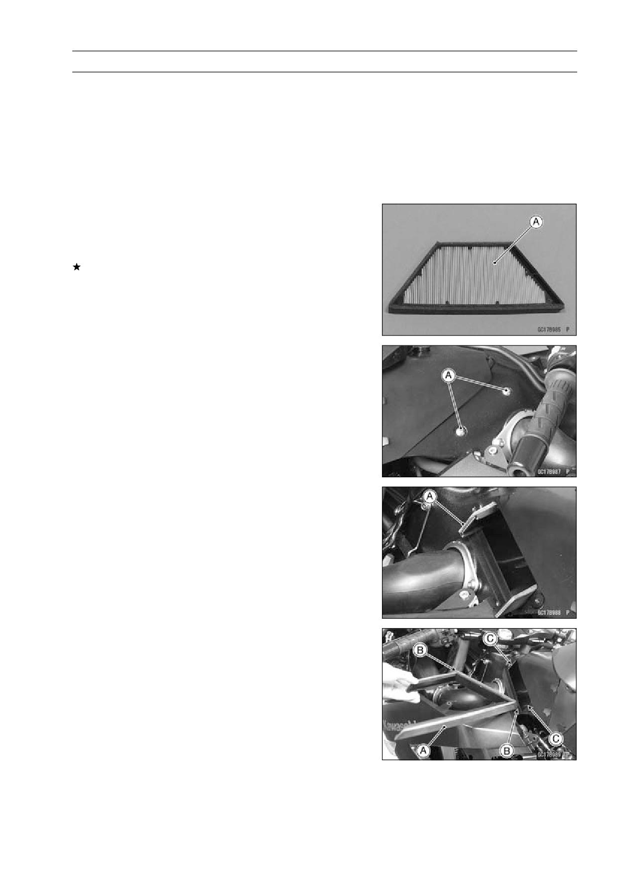
FUEL SYSTEM (DFI) 3-121
Air Line
Element Removal
• Refer to the Air Cleaner Element Replacement in the Pe-
riodic Maintenance chapter (see Air Cleaner Element Re-
placement in the Periodic Maintenance chapter).
Element Installation
• Refer to the Air Cleaner Element Replacement in the Pe-
riodic Maintenance chapter (see Air Cleaner Element Re-
placement in the Periodic Maintenance chapter).
Air Cleaner Element Inspection
• Remove the air cleaner element (see Air Cleaner Element
Replacement in the Periodic Maintenance chapter).
• Visually check the element [A] for tears or breaks.
If the element has any tears or breaks, replace the ele-
ment.
Air Cleaner Element Holder Removal
• Remove:
Air Cleaner Element (see Air Cleaner Element Replace-
ment in the Periodic Maintenance chapter)
Screws [A]
• Pull out the air cleaner element holder [A] from the hous-
ing.
Air Cleaner Element Holder Installation
• Install the air cleaner element holder [A] so that the holder
ends [B] insert along the rib [C] in the housing.
• Tighten:
Torque - Air Cleaner Element Holder Screws: 6.9 N·m (0.70
kgf·m, 61 in·lb)
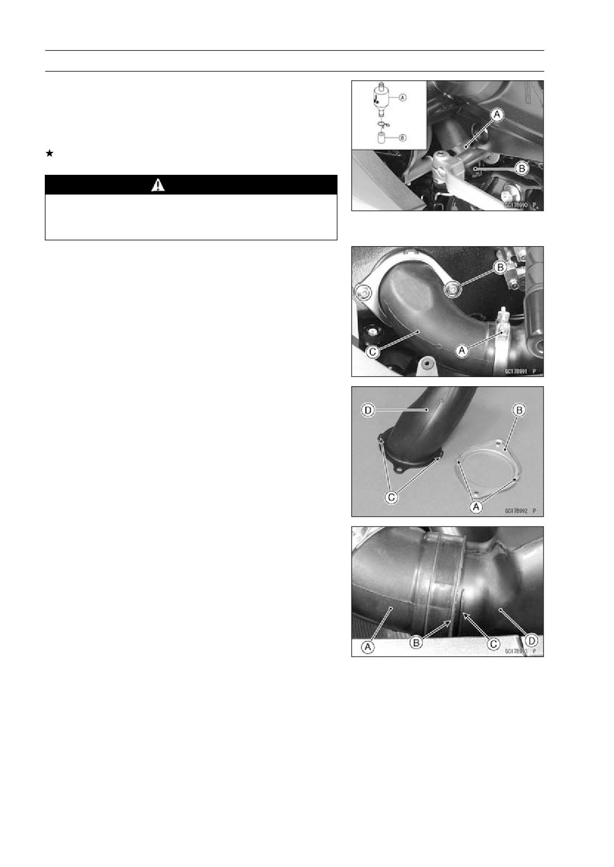
3-122 FUEL SYSTEM (DFI)
Air Line
Oil Draining
A drain hose is connected to the bottom of the air cleaner
part to drain water or oil accumulated in the cleaner part.
• Visually check the catch tank of the drain hose [A], if the
water or oil accumulates in the tank.
If any water or oil accumulates in the tank, remove the
plug [B] from the tank and drain it.
WARNING
Be sure reinstall the plug in the tank after draining.
Oil on tires will make them slippery and can cause
an accident and injury.
Rear Air Inlet Duct Removal
• Remove:
Left and Right Inner Covers (see Inner Cover Removal
in the Frame chapter)
Fuel Tank Cover (see Fuel Tank Cover Removal)
• Loosen the clamp bolt [A] on both sides.
• Remove the mounting bolts [B] and, pull off the right rear
air inlet ducts [C] to backward.
• Remove the left rear air inlet duct in the same way as right.
Rear Air Inlet Duct Installation
• Insert the projections [A] of the holder [B] in the holes [C]
of rear air inlet duct [D].
• Insert the rear air inlet duct [A] until the duct end [B] align
the line [C] of middle air inlet duct [D].
• Tighten
Torque - Rear Air inlet Duct Mounting Bolts: 9.8 N·m (1.0
kgf·m, 87 in·lb)
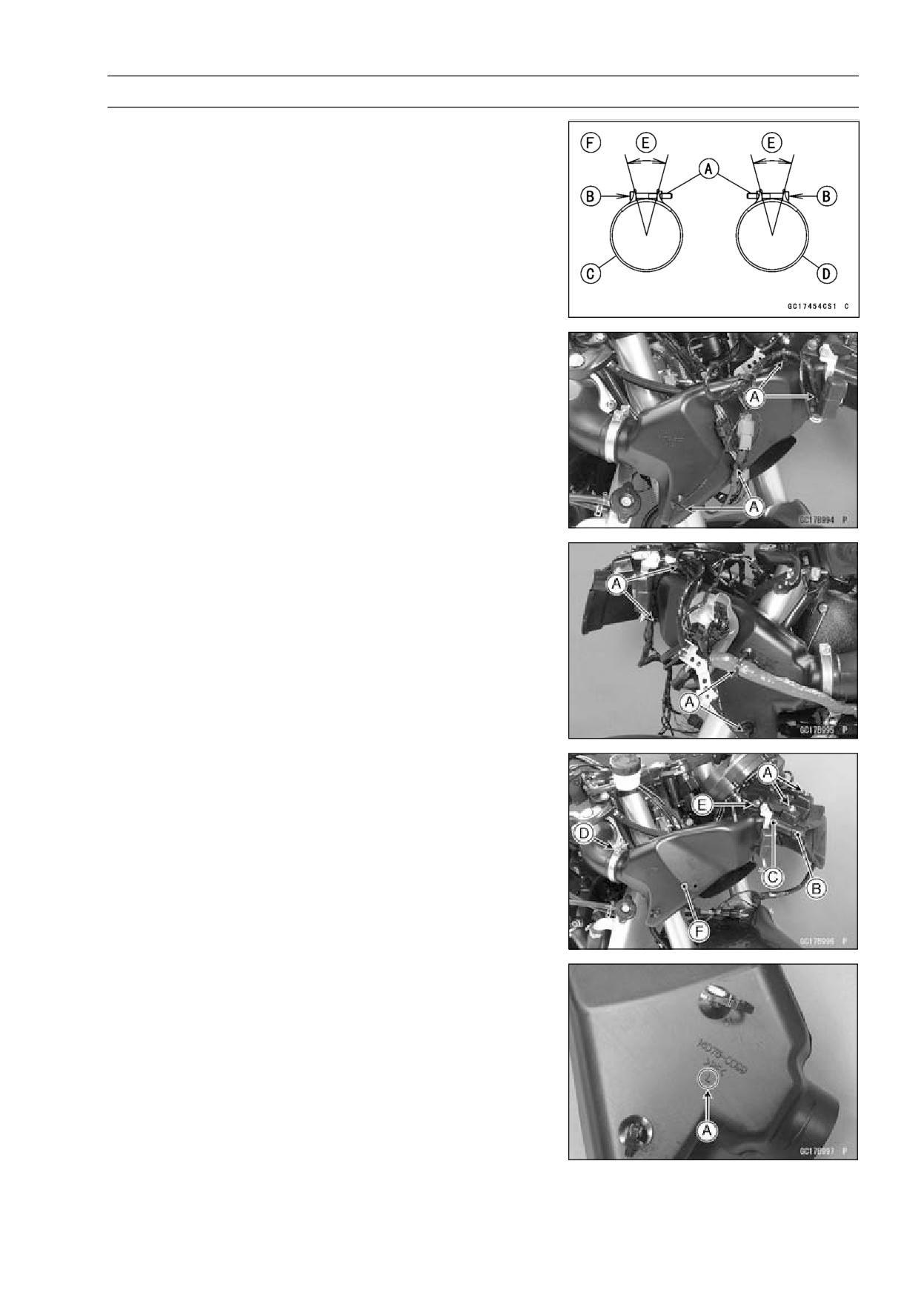
FUEL SYSTEM (DFI) 3-123
Air Line
• Install the clamp bolts [A] so that bolt heads [B] faces
direction as shown.
Left Clamp [C]
Right Clamp [D]
About 30° [E]
Rear View [F]
• Tighten:
Torque - Middle Air inlet Duct Clamp Bolts: 2.9 N·m (0.30
kgf·m, 26 in·lb)
Front and Middle Air Inlet Duct Removal
• Remove the upper fairing (see Upper Fairing Removal in
the Frame chapter).
• Open the clamps [A].
• Open the clamps [A].
• Remove:
Bolts [A]
Front Air inlet Duct [B]
Rubber Seal [C]
• Loosen the clamp bolts [D] on both sides.
• Remove the bolts [E] on both sides.
• Pull off the left and right middle air inlet ducts [F] to for-
ward.
Front and Middle Air Inlet Duct Installation
NOTE
○The left middle air inlet duct has a L mark [A] and the
right middle air inlet duct has a R mark.
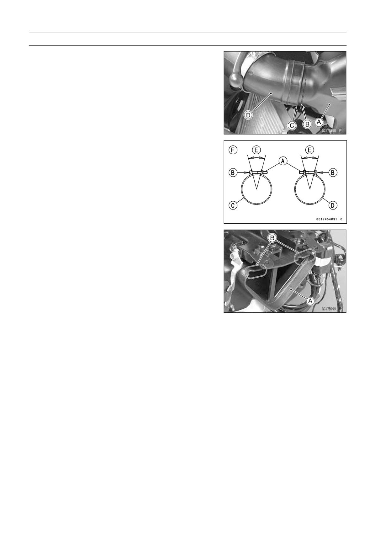
3-124 FUEL SYSTEM (DFI)
Air Line
• Insert the middle air inlet duct [A] until the line [B] align
the duct end [C] of rear air inlet duct [D].
• Tighten:
Torque - Middle Air Inlet Duct Mounting Bolts: 9.8 N·m (1.0
kgf·m, 87 in·lb)
• Install the clamp bolt [A] so that bolt heads [B] faces di-
rection as shown.
Left Clamp [C]
Right Clamp [D]
About 30° [E]
Rear View [F]
• Tighten:
Torque - Middle Air Inlet Duct Clamp Bolts: 2.9 N·m (0.30
kgf·m, 26 in·lb)
• Install the rubber seal [A] so that the hollow side [B] faces
forward.
• Insert the front air inlet duct to the rubber seal, and tighten
the bolts.
Torque - Front Air Inlet Duct Mounting Bolts: 9.8 N·m (1.0
kgf·m, 87 in·lb)
• Run the leads correctly (see Cable, Wire, and Hose Rout-
ing section in the Appendix chapter).
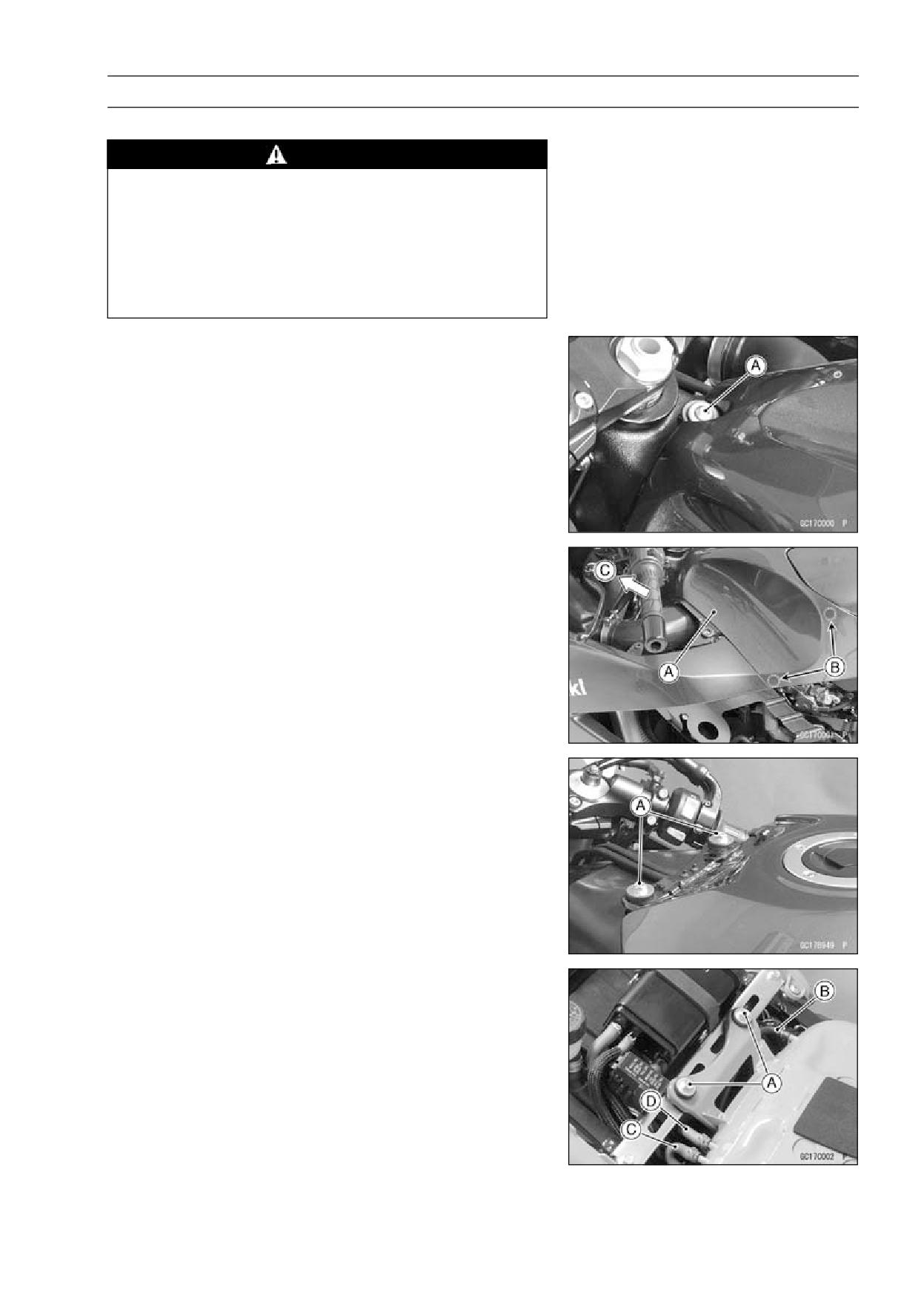
FUEL SYSTEM (DFI) 3-125
Fuel Tank
Fuel Tank Removal
WARNING
Gasoline is extremely flammable and can be explo-
sive under certain conditions. Make sure the area
is well-ventilated and free from any source of flame
or sparks; this includes any appliance with a pilot
light. Do not smoke. Turn the ignition switch OFF.
Be prepared for fuel spillage; any spilled fuel must
be completely wiped up immediately.
• Turn the ignition switch OFF.
• Remove the left and right fairing covers (see Fairing
Cover Removal in the Frame chapter).
• Disconnect the battery (-) terminal (see Battery Removal
in the Electrical System chapter).
• Remove:
Left and Right Inner Covers (see Inner Cover Removal
in the Frame chapter)
Bolt [A]
• Pull the fuel tank cover [A] evenly outward to clear the
projections [B] on both sides.
• Remove the fuel tank cover to forward [C].
• Remove the bolts [A].
• Remove:
Bolts [A]
Drain Hose [B]
• For the California model, remove the following.
Fuel Return Hose [C] (right side, red)
Fuel Tank Breather Hose [D] (left side, blue)