Aprilia scooter (manual) - part 10
-
-
REFITTING THE STANCHION TUBES AND SLIDERS
-
-
Place the slider in a vice with soft (aluminium) jaws.
-
Position the shim (1).
 WARNING
Make sure no dirt or objects fall into the slider
or the stanchion.
NOTE Apply a light film of fork oil to the seals and bushes before assembly.
-
Insert the washer.

-
Insert the oil seal.


-
Insert the retaining ring.
-
Insert the dust seal.


-
Insert the damping cylinder and the spring into the slider.

-
Insert the centring bush (2) first and then the slider into the stanchion.


-
Tighten the capscrew (3).
-
Fill oil into the fork, 7.9.5.

-
REAR SUSPENSION
-
SHOCK ABSORBER REMOVAL TORQUE WRENCH SETTINGS
Top nut (1) 50 Nm (5.0 kgm)
Lower bolt (2) 50 Nm (5.0 kgm)

-
-
-
Remove the tail, 7.1.5.
-
Release and remove the top nut (1).
-
Remove the upper bolt.
-
Release and remove the lower bolt (2).
-
Remove the shock absorber.

-
REMOVING THE LINKAGES
TORQUE WRENCH SETTINGS
Nut (2) 40 Nm (4.0 kgm)
Shock absorber bolt (4) 50 Nm (5.0 kgm)
Nut (9) 60 Nm (6.0 kgm)


-
-
Remove the air dam, 7.1.8.
-
Remove both rear side panels, 7.1.3.
-
Unhook the spring (1).
-
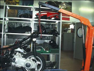
Fix the slings to the grab rail.
-
Lift the hoist arm until stretching the slings taut.
 WARNING
You will need an assistant in order to perform
this procedure safely.

-
Release and remove the nut (2) working from the right side.

-
Withdraw the engine bolt (3) from the left side and collect the washer.
-
Release and remove the shock absorber lower bolt (4).
-
Release and remove the silent-block retaining bolt (5) working from both sides.
-
Collect in the order: inner nut (6), bolt (5) and washer.


-
Release and remove the nut (7) working form the right side.
-
Withdraw the bolt from the left side and collect the washer.
-
Remove the linkages.
ELECTRICAL SYSTEM 8

SUMMARY
-
LAYOUT OF COMPONENTS 3
-
LAYOUT OF ELECTRICAL COMPONENTS 3
-
-
FOREWORD 4
-
FOREWORD 4
-
-
BATTERY 5
-
BATTERY 5
-
-
IGNITION SYSTEM AND STAND LOGIC 7
-
IGNITION SYSTEM AND STAND LOGIC 7
-
-
CHARGE SYSTEM 10
-
CHARGE SYSTEM AND POWER SUPPLY 10
-
-
STARTER CIRCUIT 12
-
STARTER CIRCUIT 12
-
-
SENSORS 15
-
SENSOR CIRCUIT 15
-
-
FAN AND REAR TOP BOX LIGHT 18
-
FAN AND REAR TOP BOX LIGHT SYSTEM 18
-
-
LIGHT CIRCUIT 20
-
LIGHT CIRCUIT 20
-
-
VISUAL AND ACOUSTIC SIGNALS 22
-
VISUAL AND ACOUSTIC SIGNALLING SYSTEM 22
-
-
BULB REPLACEMENT 24
-
BULB REPLACEMENT 24
-
-
REPLACING THE FUSES 27
-
REPLACING THE FUSES 27
-
-
BEAM SETTING 28
-
BEAM HEIGHT SETTING 28
-
BEAM HORIZONTAL SETTING. 29
-
-
WIRING DIAGRAM 30
-
WIRING DIAGRAM 30
-
-
LAYOUT OF COMPONENTS

-
LAYOUT OF ELECTRICAL COMPONENTS
Key:
-
Headlight
-
Battery
-
Spark plug
-
Main fuses
-
Coil
-
Auxiliary fuses
-
Voltage regulator
-
Tail light
-
Rear left direction indicator
-
Side stand switch
-
Starter motor
-
Warning horn
-
Starter relay
-
Front left direction indicator
-
Engine Control Unit
-
Coolant thermistor
-
ECU relay
-
Front brake light switch
-
Dashboard
-
Front right direction indicator
-
Rear brake light switch
-
Rear right direction indicator
-
Fan
-
Fuel sensor
-
-
-
FOREWORD
-
FOREWORD
-
Please read the following information before reading this section.
Note For ease of reference, the same numbering is used in the specific wiring diagrams and in the general schematics.
WIRING COLOUR CODES
Ar Orange
Az Light blue
B Blue
Bi White
G Yellow
Gr Grey
-
Brown
-
Black
R Red
Ro Pink
V Green
Vi Purple

ELECTRICAL CONNECTORS
Disconnect the electrical connectors as follows:
-
-
Press down on the locking tab, where fitted.
 WARNING
Never separate two connectors by pulling on
the wiring.
-
Grasp both connectors and pull them in opposite directions until they become separated.
-
Remove any dirt, rust, moisture, etc. from inside the connector blowing with compressed air.
-
Ensure that the wires are securely crimped to the terminals inside each connector.
NOTE A connector will only locate properly into the matching connector when it is inserted in the correct mounting position.
-
When refitting, reconnect the two connectors and ensure that they become fully engaged (where fitted, the locking tab will click audibly into place).

-
BATTERY
-
BATTERY
-
Battery rating: 12 V - 9 Ah
ACTIVATION AND MAINTENANCE

-
-
Remove the battery from the vehicle, see 7.2.1.
-
Remove the cell caps and the breather cap.
-
Fill the cells with electrolyte fluid with 1.3 specific weight.
-
Charge the battery at slow charge rate (that is, ampere rating should be 1/10th of battery rating) for at least 10 hours. Refit the battery just before delivering the vehicle to end user, that is, when vehicle is expected to cover some distance.
-
Install the battery and connect the leads and the breather hose.
-
To avoid degradation in the wintertime or while the vehicle is stored away, charge the battery for 10 hours at regular intervals (at least monthly).
-
Top up battery fluid level at regular intervals (at least monthly). Top up with distilled water only.
INSPECTION

-
In the event of abnormal operation, check the charge system first, see 8.5.1.

-
To check the battery,
-
First remove the battery from the vehicle, see
7.2.1. and proceed as follows: Visually inspect for:
-
apparent signs of sulphation (one or more cells will have become white);
-
check that fluid level is between the “MIN” and “MAX” level marks;
-
check the outer casing for leaks.
-
-
Charge the battery at slow charge rate for at least 10 hours.
-
After charging, measure electrolyte fluid density in each cell using a densimeter. Change battery when fluid density in any one cell is less than 1.26 or when loadless voltage is lower than 12V.
RETURN UNDER WARRANTY
The warranty is invalidated when:
-
the battery is damaged (dented housing, bent terminals, etc.);
-
the battery is affected by extensive sulphation (normally due to improper installation procedure and/or use).
-
electrolyte fluid level is too low (simply close the breather hole with the rubber cap before shipping to avoid this problem).

SAFETY RULES
 WARNING
Battery fluid contains sulphuric acid. Avoid
contact with skin and do not spill on your clothing. Keep the battery away from sources of heat or ignition (such as sparks). This is especially important when the battery is under charging, as it releases hydrogen which may cause a fire or explosion.
-
IGNITION SYSTEM AND STAND LOGIC
-
IGNITION SYSTEM AND STAND LOGIC
-

Key:
21. Key-operated switch
25. Engine kill switch
38. Main fuses
-
Battery
-
Auxiliary fuses
-
HT coil
-
Spark plug
-
Automatic starter
-
CDI control unit
-
Side stand switch
-
Pick up
61. Ignition relay
TROUBLESHOOTING
-
-
-
Ensure that the 7.5 A and 15 A fuses are in good condition.
-
Check the spark plug and replace as required.
-
Check the high voltage lead and the spark plug cap.
-
Check the coil.
-
Check the pick-up.
-
Connect the green-brown lead to ground. If the ignition operates, check the stand logic system.
-
Fit a substitute CDI control unit known to be in good working order.


TEST READINGS
Ignition coil test
Test the coil using a portable multimeter. Check for continuity of the primary and secondary windings. The resistance readings found need not match standard values exactly. If the windings are in good working order, resistance readings should approximate the standard values.
Coil winding resistance
Primary
0.2 ohm ± 10%
Secondary
2.9 Kohm ± 10%
Warning: Disconnect the spark plug cap before measuring.
Pick-up test
-
Disconnect the pick-up connector.
-
Measure resistance across the terminals of the yellow/blue and yellow/green wires using a multimeter set to the 1000 Ohm range. Correct reading is 105 Ohm ± 10% (at 20 °C).
-
Replace the pick-up when detected reading indicates infinite resistance or is below the specified range.

CDI CONTROL UNIT test
This is a capacitive discharge control unit with digital spark advance control based on engine rpm. The control unit is fitted with two connectors. The eight-pin connector is in use.
Pin-out
-
Direction indicator control
-
Not connected
-
Ignition coil control
-
Not connected
5. +15 input
-
Pick-up input
-
Starter control
-
Ground

TEST READINGS
Starter relay test
To test relay operation:
-
-
Feed 12 Volts to the two male terminals (85 - 86).
-
Check for continuity between the other two terminals (87 – 30) using a multimeter set to the Ohm range.
Correct reading when relay is fed: 0 ohm Correct reading when relay is not fed: ohm
Replace the relay if the readings obtained deviate from those specified.

SIDE STAND SWITCH TEST
Ensure that there is no obstruction to side stand (1) rotation. Check for the following:
-
Inspect the springs (2) for any sign of damage, wear, rust or weakening.

-
The side stand should rotate freely. Grease the joint if needed, see 2.2.1.
The side stand (1) is fitted with a safety switch (3) that
inhibits ignition or shuts down engine operation whenever the side stand (1) is down.
To test safety switch (3) operation:
-
Sit astride the vehicle.
-
Raise the side stand (1).
-
Start the engine.
-
With the throttle twistgrip released and the engine idling, lower the side stand (1). This should cause the safety switch (3) to cut in.
This is what should happen next:
-
the engine should stop;
-
the side stand light “
 “
on the dashboard should light up.
“
on the dashboard should light up.
NOTE When this is not the case, replace the switch (3).
Stand position
Wires
M
v
N
Up

Down

SWITCH TEST
Check switch continuity using a multimeter.
Change any switch that operates other than as specified in the relevant diagram.
Starter switch
Wires
V
R
ON

OFF

LOCK

Engine kill switch
Wires
Bi/B
M/V
OFF

ON


-
CHARGE SYSTEM
-
CHARGE SYSTEM AND POWER SUPPLY
-

Key:
-
Main fuses
-
Power socket
-
Battery
-
Generator
-
Voltage regulator


CHECKING CHARGE VOLTAGE
-
-
-
Check battery fluid level, 2.4.3.
-
Check battery voltage, 2.4.1.
-
Start the engine and rev it up to 5000 rpm (rotate throttle twistgrip up to 1/4th of travel).
-
Set the light switch to “
 ”.
”. -
Measure DC voltage across the positive (+) and negative (–) battery terminals using a multimeter.
-
If the reading found is less than 13 V or more than 15 V:
-
Test alternator operation under no-load conditions and check continuity of alternator and voltage regulator.
Correct charge voltage: 13-15 V(DC) at 5000 rpm.

ALTERNATOR LOADLESS OPERATION TEST
-
Disconnect the voltage regulator connector (1).
-
Start the engine and rev it up to 5000 rpm (rotate throttle twistgrip up to 1/4th of travel).
-
Measure AC voltage across the three yellow (G) wires using a multimeter. Test across all terminals alternately. Any reading below 50 V indicates a faulty alternator.

ALTERNATOR CONTINUITY TEST
With the engine stopped:
-
Disconnect the voltage regulator connector (1).
-
Check for continuity across the yellow (G) wires coming from the stator.
-
Check insulation of stator mount.
Correct resistance reading: 0.1 – 1 ohm
Correct resistance across wires and stator mount:
∞(infinite)
-
STARTER CIRCUIT
-
STARTER CIRCUIT
-

Key:
21. Key-operated switch
23. Starter button
27. Parking/left brake light bulb
29. Parking/right brake light bulb
-
Front brake light switch
-
Rear brake light switch
-
Brake light /starting interlock relay
-
Starter relay
-
Starter motor
-
Main fuses
41. Auxiliary fuses
NOTE The white/black wire Bi/N (1) is fed by the ignition relay 61 (see ignition system diagram).

TROUBLESHOOTING
-
-
Check battery condition, 2.4.1.
-
Check fuse condition, 8.12.1.
-
Check the ignition switch.

-
Check the engine kill switch.

-
Check the brake light/starting interlock relay, 8.4.1.
-
Check the ignition relay, 8.4.1.
-
Check the start button.
-
Check the starter relay.
-
Check the starter motor.

STARTER RELAY TEST
-
Disconnect the two-way connector (1) (coloured white).
-
Release the relay (2) from its mount.

-
Slip off the two rubber gaiters (3-4).
-
Disconnect the wires from their respective terminals on the relay (2).

-
Feed 12 V to the two terminals inside the connector (1) at the relay end.
-
Check for continuity across the two contact screws on the relay (2) using the multimeter set to the Ohm range.
Correct reading when relay is fed: 0 ohm Correct reading when relay is not fed: ohm
-
Change the relay (2) when the readings found deviate from the specified values.
STARTER MOTOR TEST
-
Remove the starter motor and connect it to a 12 V battery in good working order.
-
If the motor is not operating properly, check for brush wear and inspect slip ring.
SWITCH TEST
Check switch continuity using a multimeter.


Front brake light switch
Wires
r/N
Bi/n
Lever pulled

Lever released
Rear brake light switch
Wires
r/N
Bi/n
Lever pulled

Lever released
Change any switch that operates other than as specified in the relevant diagram.
Starter button
Wires
G/R
R/N
Start command


-
SENSORS
-
SENSOR CIRCUIT
-

Key:
-
Fuel level indicator
-
Complete dashboard
-
Coolant thermistor
-
Oil pressure sensor
60. Fuel level sensor
NOTE Terminal 2 of the 7-way connector is fed a positive voltage which is controlled by the switch.
COOLANT TEMPERATURE
Dashboard indicator test
-
-
Disconnect the coolant thermistor connector and connect a resistor at the connector end.
-
Set the key to ON and note the dashboard indicator reading.
Ratings of resistors to be connected to the connector
-
Resistor rated <75 ohm : corresponds to full scale indication
-
Resistor rated 105 ohm : beginning of red area ± 5°
-
Resistor rated >1000 ohm : beginning of scale.


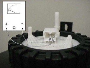
Coolant thermistor test
-
-
Remove the thermistor (1), 5.4.1.
-
Set a multimeter (2) to the Ohm range and attach the multimeter leads to the thermistor (3) as shown in the figure.
-
Suspend the thermistor (1) in a container (3) filled with coolant.
-
Suspend a thermometer (4) with a 0 -150°C (32 - 302°F) range in the container.
-
Place the container on a gas burner (5) and heat up the coolant gradually.
-
Check the temperature reading of the thermometer (4) and the thermistor (1) output indicated by the multimeter.
Thermistor output should vary with temperature as indicated in the table below.
Coolant temperature
Correct reading ()
100 (°C)
212 (°F)
144
80 (°C)
176 (°F)
262
60 (°C)
140 (°F)
512
40 (°C)
104 (°F)
1090
NOTE Change the thermistor (1) when meter reading does not vary with temperature, or when the readings found deviate too much from the values indicated in the table.
FUEL LEVEL
Dashboard indicator test
-
Disconnect the sensor connector and connect a resistor across the yellow-green and blue wires at the connector end.
-
Set the key to ON and note the dashboard indicator reading.
Ratings of resistors to be connected to the connector
-
Resistor rated 10 ohm : full tank indication
-
Resistor rated 38 ohm : half scale +-5°
-
Resistor rated 90 ohm : empty tank and light on

Fuel sensor test
-
-
Disconnect the sensor connector, 4.1.3.
-
Connect an ohmmeter to the yellow-green and blue wire terminals. Measure resistance output at different fuel levels.
-
Correct reading with a full tank: less than 10 ohm
-
Correct reading with 8 litres of fuel: 38 ohm ± 10%
-
Correct reading with empty tank: greater than 90 ohm


Low fuel light test
-
-
Disconnect the sensor connector, 4.1.3.
-
Connect an ohmmeter to the orange-black and blue wire terminals.
-
Check for continuity across the terminals when fuel inside the tank is less than 1.5 litres. With any other quantity of fuel resistance should be infinite (open circuit).
Engine oil pressure test

-
Disconnect the sensor from the system, see Engine Workshop Manual 0.1.2.
-
With the engine running, there should be no continuity
to ground. If not so, ensure that engine oil level is correct and replace sensor.
-
FAN AND REAR TOP BOX LIGHT
-
FAN AND REAR TOP BOX LIGHT SYSTEM
-
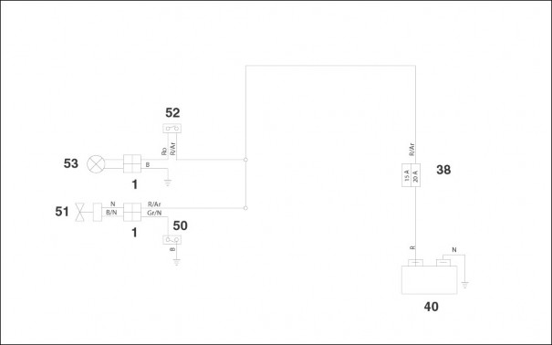
Key:
38. Main fuses
40. Battery
-
Thermal switch
-
Fan
-
Rear top box light switch
-
Rear top box light

FAN SYSTEM CHECK
Cooling fan test

To check for proper fan operation:
-
-
Remove the air dam, 7.1.8.
-
Disconnect the electric connection (1) that operates the cooling fan.
-
Feed 12 VDC to the fan. Observe the correct polarity. Check fan for proper operation.


Thermal switch test
-
Remove the air dam, 7.1.8.
-
Disconnect the two connectors.
-
Release and remove the thermal switch (2).
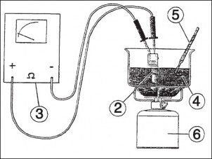
-
Set a multimeter (3) to the Ohm range to the thermal switch (2) as shown in the figure.
-
Suspend the thermal switch (2) in a container filled with coolant (4).
-
Suspend a thermometer (5) with a 0-150°C (32 -302°F) range in the container.
-
Place the container on a gas burner (6) and heat up the coolant gradually.
-
Check the temperature reading of the thermometer (4) and the resistance reading indicated by the multimeter.
-
The switch operating threshold is between 90 and 100°C (194 - 212°F). When this threshold is exceeded, tester reading should change from to 0 ohm.
